Leica FluoCombi III User manual

2
Leica FluoCombi III™ – User manual
Dear User,
Thank you for your confidence in our products. We trust you will enjoy them
and we wish you great success with the high-quality and high-performance
products from Leica Microsystems.
In developing our instruments, we place great value on simple, self-
explanatory operation. Nevertheless, please take the time to read the oper-
ating instructions so that you know the advantages and possibilities offered
by your stereomicroscope and can use them most efficiently. Should you
ever have any questions, please consult your local Leica representative.
We are gladly at your service. Customer service is a big thing with us. Not
only before the sale, but afterwards as well. You will find the address of
your nearest local representative, as well as valuable information about
Leica Microsystems products and services, from Leica Microsystems on
our web site at www.leica-microsystems.com.
Leica Microsystems (Switzerland) Ltd.
Stereo & Macroscope Systems
www.stereomicroscopy.com

3Leica FluoCombi III™ – Overviews
Overviews
Operating and function elements
1Fine focusing with mount thread for a 5×or 20×HR objective (requires an adapter)
2Clamping screw for locking the fine focusing
3Mechanism for parcentric swinging to the stereo or micro mode
4Slot for filter slide for dichroic mirror of your choice
5Mount for UV protection screen
Fig. 1 Leica FluoCombi IIITM, 5×planapo HR objective rotated into the beam path
9
3
4
7
1
6
5
8

4
6Clamping screw for fastening the UV protection screen
7Clamping screw for locking the UV protection screen in the desired tilt position
8Clamping screw for fastening the optics carrier in the microscope carrier of the FluoCombi III™
9Clamping screw for fastening the focusing stop
Leica FluoCombi III™ – Overviews
Fig. 2 Leica FluoCombi IIITM, 1×planapo objective rotated into the beam path
2
8
6
7
5
9
3
1

5
Leica FluoCombi III™ – User manual
Contents
Page
Overviews . . . . . . . . . . . . . . . . . . . . . . . . . . . . . . . . . .
Operating and function elements . . . . . . . . . . . . 3, 4
1. General notes . . . . . . . . . . . . . . . . . . . . . . . . . . 6
1.1 The user manual . . . . . . . . . . . . . . . . . . . . . . . . 6
1.1.1 Diagrams . . . . . . . . . . . . . . . . . . . . . . . . . . . . . . 6
1.2 Description . . . . . . . . . . . . . . . . . . . . . . . . . . . . 6
2. Assembly
2.1 Expansion diagram . . . . . . . . . . . . . . . . . . . . . . 7
2.2 Standard delivery . . . . . . . . . . . . . . . . . . . . . . . 8
2.2.1 Additional components . . . . . . . . . . . . . . . . . . 8
2.3 Assembly sequence . . . . . . . . . . . . . . . . . . . . . 9
2.4 Column with focusing drive
and base of stand . . . . . . . . . . . . . . . . . . . . . . 10
2.5 Focusing stop . . . . . . . . . . . . . . . . . . . . . . . . . 10
2.6 Transport anchorage . . . . . . . . . . . . . . . . . . . 11
2.7 FluoCombi III™ and focusing drive . . . . . . . 11
2.8 Optics carrier . . . . . . . . . . . . . . . . . . . . . . . . . 12
2.9 Objectives . . . . . . . . . . . . . . . . . . . . . . . . . . . . 13
2.10 UV protection screen . . . . . . . . . . . . . . . . . . . 14
2.11 Dichroic mirrors . . . . . . . . . . . . . . . . . . . . . . . 14
2.12 Illumination . . . . . . . . . . . . . . . . . . . . . . . . . . . .14
3. Operation
3.1 Parfocality . . . . . . . . . . . . . . . . . . . . . . . . . . . . 15
3.2 Magnification . . . . . . . . . . . . . . . . . . . . . . . . . 17
4. Appendix
4.1 Weights . . . . . . . . . . . . . . . . . . . . . . . . . . . . . . 18
4.2 Dimensions . . . . . . . . . . . . . . . . . . . . . . . . . . .19
4.3 Optical data . . . . . . . . . . . . . . . . . . . . . . . . . . .22
4.4 Technical data . . . . . . . . . . . . . . . . . . . . . . . . .24

Leica FluoCombi III™ – General notes
6
1. General notes
1.1 The user manual
Leica FluoCombi III™ is an accessory for the
Leica MZ16 F, MZ16 FA fluorescence stereomi-
croscopes. Together with your Leica FluoCombi III™,
you receive an interactive CD-ROM with the user
manual for all products from Leica Microsystems
(Switzerland) in the current EU languages. User
manuals and updates are also available for you
to download and print from our web site at
www.stereomicroscopy.com. The following
user manuals are important for your
Leica FluoCombi III™:
– M2-166-2 Leica FluoCombi III™: It describes the
specific functions of the FluoCombi III™
– M2-160-4 for MZ16 FA and M2-160-5 for MZ16 F
describe the functions of the motorized and
the manual version
– M2-216-1 describes the lamp housing and
its functions
– M2-105-0 Leica M Stereomicroscopes: It
contains all the detailed information about the
use of the stereomicroscope, the optical data
with stereo objectives, and the safety and care
instructions
– M1-267-1 Leica motor focus system: describes
the motorized focusing
Read the user manuals listed
above before the startup procedure.
In particular, please follow the safety
instructions.
To maintain the unit in its original condition and to
ensure safe operation, the user must follow the
instructions and warnings contained in these user
manuals.
1.1.1 Diagrams
Pages 3 and 4 contain figures showing the
Leica FluoCombi III™ with the function elements.
Numbers in parentheses within the descriptions
refer to the number of the figure and the items in
the figure.
Example (1.4): Figure 1is located on page 3, and
the item 4is the insert for dichroic mirrors.
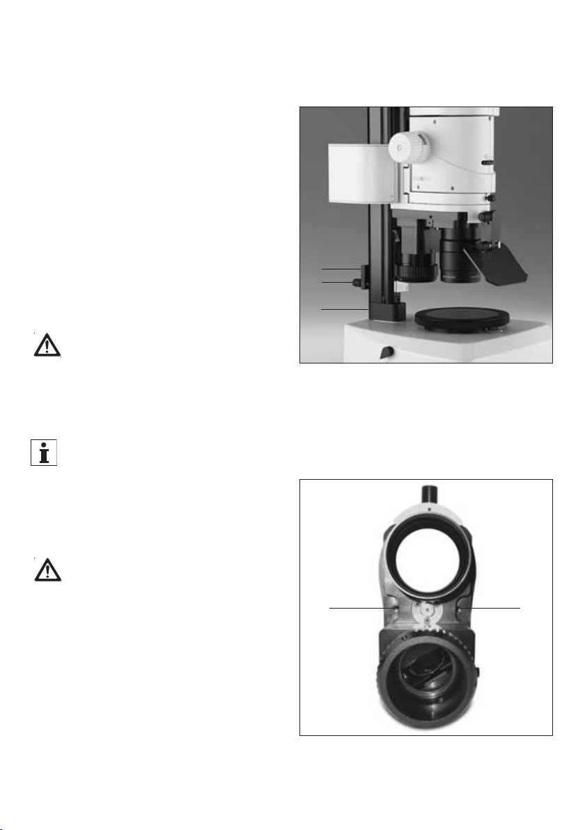
1.2 Description
Leica FluoCombi III™ is an accessory for the Leica
MZ16 F, MZ16 FA fluorescence stereomicroscopes
and allows for quickly switching between a stereo
objective and an HR (High Resolution) micro
objective. In stereo mode, the 1×plan and planapo
objectives offer generous viewing fields, large
working distances and an excellent depth of field
for manipulating and dissecting.
Micro mode allows for exactly identifying the
finest fluorescent features at a microscopic reso-
lution of 1500 pairs of lines/mm. The zoom is also
effective in micro mode so that the magnification
measures 460×using the 5×HR objective. Using
16×eyepieces results in a maximum magnification
of 736×. The comfortable binocular observation is
ensured in stereo and micro mode.
MZ16 F and MZ16 FA are high-performance stereo-
microscopes for fluorescence applications. The
patented, separate TripleBeam™ light path for
fluorescence illumination and the patented
FLUOIII™ filter system provide highest-quality
fluorescence images. Every existing instrument
can be fitted with the Leica FluoCombi III™ in a
few simple steps.

7
2.1 Expansion diagram
Leica FluoCombi III™ – Assembly
2. Assembly
10 445 631
10 445 367 HL
10 446 352 HL RCTM
10 445 363
10 445 387
10 445 822
10 446 229
Filter
10 447 284
10 447 285
10 447 286
10 447 287
10 447 288
10 447 289
10 446 271
10 447 185 500mm
Motor focus
10 447 041 500mm
10 447 160
10 445 301
10 445 302
10 445 303
MZ16 F
10 447 064
106z
11 504 066
11 504 069
FluoCombi IIITM
10 447 324
MZ16 FA
10 447 063
10 447 243
5x HR
10 447 338
10 447 085 20x HR
Optem / Mitutoyo
10 447 290
10 447 291
10 447 292
10 447 293
10 447 294
10 447 295
10 445 819
10 447 157
Plan/Planapo

8Leica FluoCombi III™ – Assembly
2.2 Leica FluoCombi III™ standard delivery
– Leica FluoCombi III™ with microscope carrier
(Fig. 3) for the MZ16 F and MZ16 FA optics car-
rier, mechanism for swinging into the stereo or
micro mode, fine focusing with mount thread
for an HR objective and for a 1× plan or planapo
objective
– UV protection screen (7.11)
– Focusing stop with stops (7.3)
– Column adapter (7.2a)
2.2.1 Additional components
– HR planapo objective 5×/0.5 LWD (Fig. 4),
FAA 19mm or
– Adapter (5.1) for Mitutoyo/Optem objectives and
screw-in adapter (5.2) as well as the
corresponding objective
– Fluorescence stereomicroscope (7.5) with third
TripleBeam™ beam path, FLUOIII™ filter sys-
tem, rapid filter changer and Leica lamp hous-
ing for mercury high-pressure lamps as well as
binocular tube, eyepieces, stand and focusing
drive
–1×Plan or planapo objective (7.9)
– Dichroic mirror of your choice (Fig. 6)
Assembly and setup of Leica MZ16 F, MZ16 FA
fluorescence stereomicroscope and the fluores-
cence illumination are described in the respective
operating instructions (see p. 6).
Binocular tube, eyepieces, stands, mercury vapor
lamp, etc. are described in the operating instruc-
tions M2-105-0, M2-160-5, M2-160-4, M2-216-1.
Fig. 6 Dichroic mirror
Fig. 5 Adapter (1) for Mitutoyo/Optem objectives
and screw-in adapter (2)
Fig. 4 HR planapo objective 5×/0.5 LWD
Fig. 3 Leica FluoCombi IIITM
1
2

9Plan or planapo objective 1×
10 HR planapo objective 5×(or adapter and
Mitutoyo/Optem objective)
11 UV protection screen
12 Filter sets upon demand in the filter
changer and analogous with a dichroic filter
in the FluoCombi III™
13 Photo equipment (if available)
14 Gliding stage or thermal stage (if available)
9
2.3 Assembly sequence
1Base of stand
2Focusing drive with column (manual or
motorized) and column adapter (2a)
3Focusing stop
4Leica FluoCombi III™
5Optics carrier
6Binocular or video/photo tube and eyepieces
7Lamp housing with high-pressure lamp and
stray-light protection
8Supply unit
Leica FluoCombi III™ – Assembly
Fig. 7 Leica MZ16 F with Leica FluoCombi III™
7
2
2a
3
14
8
6
13
1
12
5
4
11
9
10

Leica FluoCombi III™ – Assembly
2.5 Focusing stop
The focusing stop is used for safety
purposes and must always be correctly set with
respect to the micro objective.
Fasten the focusing stop (8.2) to the column
with the clamping screw (8.3).
Set the focusing stop at a height so that
the micro objective can never hit the stand or
table surface or the object during focusing and
swinging. Working distance 5×HR objective:
19mm, 20×HR objective 13mm.
With a correctly set focusing stop, the two
stops prevent focusing too low, either manually or
motorized.
If the focusing stop is set too low
– the objective could be damaged.
– the object could be crushed or damaged.
– if the lowest focus position is approached too
quickly using the motor focus, the fingers of the
operator could be pinched between objective
and object.
Fig. 9 Leica FluoCombi III™ from below
1Transport safety screws
Fig. 8
1Column adapter
2Focusing stop
3Clamping screw for fastening
the focusing stop
11
2.4 Column with focusing drive ➜base of
stand
First, attach the column adapter between stand
column and base. It is used to ensure that the
center of the objective lies exactly over the center
of the stage.
Fasten the column adapter (8.1) with the
3 hexagon-head screws on the column.
Fasten the column with the column adapter on
the stand base according to the operating
instructions M2-105-0.
1
2
3
10

11
Leica FluoCombi III™ – Assembly
2.7 FluoCombi III™ ➜focusing drive
The Leica FluoCombi III™ must never be
unscrewed. All mechanical and optical compo-
nents are exactly adjusted at the factory.
To attach the FluoCombi III™ on the focusing
drive, the mount thread for the stereo objective
must be turned to the observer. Only in this posi-
tion is the thread accessible for mounting the
FluoCombi III™.
Turn the thread for the stereo objective (10.1) to
the observer by using the swinging mechanism.
Only in this position is the thread accessible for
mounting the FluoCombi III™ on the focusing
drive.
Fit in and hold FluoCombi III™ (10.2) in the two
plugs (at the back of the yoke, not visible in the
figure) on the focusing drive.
Insert the hexagon-head screw (10.3) through
the bore and tighten it on the focusing drive.
Fig. 10 Leica FluoCombi III™ from the front
1Mount for stereo objective
2Leica FluoCombi III™
3Hexagon-head screw for fastening the
FluoCombi III™ on the focusing drive
2
1
3
2.6 Transport anchorage
Remove transport locking screws (9.1) on both
sides of the FluoCombi III™ and screw them into
the respective threads for storing for transport at
a later time.
• The swinging mechanism is now released.
Always secure the FluoCombi III™ during
transport with these two transport safety screws.
Otherwise, the mechanism could be damaged
and maladjusted.

12 Leica FluoCombi III™ – Assembly
Fig. 11 Leica FluoCombi III™ with Leica MZ16 F
1Clamping screw for fastening
the optics carrier
2MZ16 F, MZ16 FA optics carrier
3Thread for plan or planapo objective 1×
4Plan or planapo objective 1×
5Thread for HR objective
6Fine focusing
7Clamping screw for fixing the fine focusing
6
7
1
2
3
4
5

13
Leica FluoCombi III™ – Assembly
Turn the thread for the micro objective (11.5) to
the observer.
Hold the fine focusing (11.6) or lock it with the
clamping screw (11.7).
Tighten the 5×HR objective counterclockwise
in the thread mount.
OR
Tighten the adapter (13.1) for Mitutoyo/Optem
objectives and in the thread (6.5) using the
screw-in adapter (13.2).
Tighten the corresponding objective at the
adapter (13.1).
Fig. 12 HR planapo objective 5×
Fig. 13
1Adapter for Mitutoyo/Optem objectives
2Screw-in adapter
2.8 FluoCombi III™ ➜ optics carrier
The optics carrier may not be laterally
rotated in the microscope carrier of the
FluoCombi III™ since the 3rd beam path of the
stereomicroscope and the FluoCombi III™ are
adjusted to each other.
Loosen the clamping screw (11.1) and remove
the dust cover in the microscope carrier of the
FluoCombi III™.
Carefully insert the optics carrier (11.2) in the
microscope carrier and align it so that the
optics carrier is flush with the microscope
carrier.
Tighten the clamping screw (11.1).
The assembly of the remaining components is
similar to the binocular tube, eyepieces, etc., see
M2-105-0, and the fluorescence illumination, see
M2-160-0.
2.9 Objectives
FluoCombi III™ is adjusted so that the focused
position remains sharp (parfocal) and centered
(parcentric) with every zoom position if used
with a 1×plan or planapo objective and a 5×or
20×HR objective in the stereo and micro mode.
Hold the objectives during assembly and disassem-
bly so that they do not fall onto the stage plate.
Remove specimens from the stage plate.
Turn the thread for the stereo objective (11.3) to
the observer by using the swinging mechanism.
Tighten the 1×plan or planapo objective (11.4)
counterclockwise in the thread mount.
1
2

14 Leica FluoCombi III™ – Assembly
2.12 Illumination
Please adjust the Hg lamp precisely
according to the M2-160-0 operating instructions
so that you can achieve a homogenous light spot
and good fluorescence even in micro mode.
Fig. 14 UV protection screen
1UV protection screen with holder
2Mount for UV protection screen
3Clamping screw for fastening the
UV protection screen
4Clamping screw for locking the
UV protection screen in the desired tilt
5Slot with dichroic mirror
2
3
4
5
1
2.11 Dichroic mirrors
Use dichroic mirrors (2-color-coated) in the Fluo-
Combi III™ analogous to the filter sets used in the
filter changer of the stereomicroscope. The mount
of the dichroic mirror is magnetically fixed in the
mount to ensure a correct alignment.
Insert the mount with the dichroic mirror (Fig. 6) in
the slot for the filter slide (14.5) so that the guide
pin points down and the marking can be read on
the outside.
Dichroic mirror marking
GFP GFP1
GFP Plus GFP2
GFP Plant GFP3
UV UV
Blue B
Green G
Texas Red TXR
CFP CFP
YFP YFP
DsRED DSR
2.10 UV protection screen
Never work without UV protection
screen!
Fasten the holder with UV protection screen
(14.1) at the mount (14.2) using the clamping
screw (14.3).
Loosen the clamping screw (14.4).
Tilt the UV protection screen (14.1) so that the
operator cannot look directly onto the light spot.
Tighten the clamping screw (14.4).

15
3.1 Setting the parfocality
If a 1×plan or planapo objective and a 5×or
20×HR objective is used, the focused position in
stereo and micro mode remains sharp (parfocal)
and centered (parcentric) with every zoom posi-
tion. For this reason, it is important to adjust the
parfocality precisely as described.
• We recommend performing the diopter setting
in transmitted or incident light. If the fluores-
cence illumination is activated, block the light
using the light stop and rotate the dummy filter
carrier into the beam path.
• Use a very fine, flat object that can still be
focused with precision at the highest magnifi-
cation.
• Zooming, focusing and adjusting interpupillary
distance, eyecups, diopter settings, working
distance, illumination see M2-105-0 or M2-160-4
(MZ16 FA) and M2-160-5 (MZ16 F) operating
instructions.
The following settings must be performed by every
user only once.
Leica FluoCombi III™ – Operation
3. Operation

16 Leica FluoCombi III™ – Operation
Observe a flat test object and focus with fine
focusing drive.
Select the highest zoom setting.
Optimize the image sharpness.
Rotate the eye lenses counterclockwise in the
direction of «+» until the stop (+5 diopter setting).
Do not look into the eyepieces during the pro-
cedure.
Select the lowest zoom setting.
Look into the eyepieces and close one eye
each. Observe the test object with one eye and
slowly rotate the eye lense at the respective
eyepiece clockwise in the direction of «–» until
the view of the test object is sharp.
Repeat the same for the other eye.
Checking the parfocality:
Select the highest zoom setting.
Observe the test object with both eyes and
adjust the focus, if necessary.
Check the image sharpness from the lowest to
the highest zoom position.
• The image sharpness must remain constant
(parfocal). If this is not the case, repeat the
procedure.
3.1.1. Stereo mode
Ensure that the focusing stop (15.4) is set
so that the micro objective can never hit the stand
or table surface or the object during focusing and
swinging (see Chapter 2.5).
Swing the 1×plan or planapo objective (15.1) to
the observer.
Set the eye lenses at both eyepieces to diopter
setting «0».
Select the lowest zoom setting.
Set the working distance (15.2) with the coarse
focusing drive: 60mm for 1×plan, 55mm for
1×planapo.
Fig. 15 Planapo objective 1×rotated into the
beam path
1Planapo objective 1×
2Working distance
3HR planapo objective 5×
4Focusing stop
1
4
3
2

3.1.2. Micro mode
Swing the HR objective (16.1) to the observer.
Select the lowest zoom setting.
Sharply focus the object with fine focusing
(16.2).
Working distance with 5×HR objective: 19mm
and with 20×HR objective 13mm.
Refocus little by little and continuously up to the
highest zoom position.
Lock the fine focusing with the clamping screw,
if needed, to avoid unintentional adjustment
changes.
The focused position now remains sharp (parfo-
cal) and centered (parcentric) in stereo and micro
mode for every zoom position.
3.2 Magnification, field of view
The magnification changer is effective in stereo
and micro mode. Magnification factors of the
micro objectives with Leica:
• HR objective 5×: 4×
• HR objective 20×: 8×
The table with the optical data is located
on page 22.
17
Leica FluoCombi III™ – Operation
Fig. 16 HR planapo objective 5×rotated into the
beam path
1HR planapo objective 5×
2Fine focusing
3Planapo objective 1×
1
3
2

18 Leica FluoCombi III™ – Operation
4.1 Weights
FluoCombi III™ 3.220kg
HR planapo objective 5×0.5kg
HR objective 10×0.2kg
HR objective 20×0.2kg
Planapo objective 1×0.74kg
Plan objective 1×0.78kg
Leica MZ16 F optics carrier 3.420kg
Leica MZ16 FA optics carrier 3.14kg
Optics carrier 3.82kg
ErgoTube™ 10°–50° 1.7kg
Trinocular video/photo tube 100% 1.595kg
Wide-field eyepieces for persons
wearing glasses 10×/21B 0.158kg
GFP filter set 0.04kg
UV filter set 0.06kg
Lamp housing 106Z for 50 W 2.26kg
Lamp housing 106Z for 100 W 2.4kg
Hg lamp 50 W 0.1kg
Hg lamp 100 W 0.08kg
Stray-light protection 0.58kg
4. Appendix
Table of contents
Other Leica Microscope manuals

Leica
Leica TCS SP8 User guide

Leica
Leica SP5 II User manual

Leica
Leica DM6000 M User manual

Leica
Leica DM750 M User manual

Leica
Leica DM5500 B User manual

Leica
Leica Sp5 WLL STED Operation instructions

Leica
Leica SP8 User manual

Leica
Leica DMI6000B User manual

Leica
Leica BM E User manual

Leica
Leica EZ4 E User manual