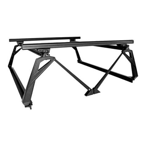
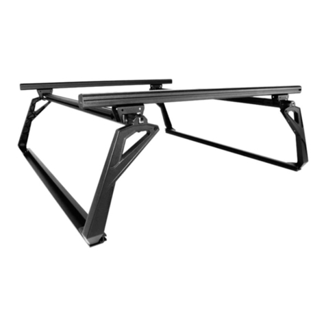
Leitner ACS FORGED User manual

ASSEMBLY / INSTALLATION INSTRUCTIONS:
ACTIVE CARGO SYSTEM PART NUMBERS:
04-60-FA-1307 (2005-2015 Toyota Tacoma Short Bed]
04-73-FA-1328 (2005-2015 Toyota Tacoma Long Bed]
04-60-FA-1311 (2016-2020 Toyota Tacoma Short Bed]
04-73-FA-1329 (2016-2020 Toyota Tacoma Long Bed]
TOOLS REQUIRED
•Torque wrench
•4mm HEX BIT socket
•5mm HEX BIT socket
•6mm HEX BIT socket
•13MM WRENCH
TOOLS Included
•t40 torx
•t55 torx
INSTALLATION TIME
SKILL LEVEL
3= intermediate
2-3 Hours
Basic knowledge of hand tools required
12 4
3
INSTALLATION INSTRUCTIONS
V1 | Page 2

▼READ BEFORE INSTALLING ACTIVE CARGO SYSTEM▼
1. there are 2 different uprights clearly marked A & B. The A bracket is used on the passenger
side by the cab and on the drivers side by the tailgate. the B upright is used by the drivers
side cab and passengers side tailgate. Keep this in mind when assembling the ACS.
2. Don’t over-tighten bolts. All 10mm bolts = (40lb-ft) All 8mm bolts = (16ft-lb) All 6mm bolts = 10ft-lb) Rail clamp bolts {10ft-lb}
3. Note: drop in plastic bed liners will need to be removed before installing Active cargo system.
4. Lay down a large area of carpet or blankets as a work area to avoid scratching parts during assembly.
5. Two extra rivet nuts are included in case you make a mistake during assembly.
6. Take your time to do it right, measure twice, drill once.
`
7. Although the Active Cargo System is light having a friend to help is recommended.
▼ ASSEMBLY OVERVIEW ▼
V1 | Page 3
TAILGATE
drivers side rail
tacoma down tube
load BAR 60”
TOP BAR
“B” UPRIGHT
“A” UPRIGHT
STATIONARY load
BAR BRACKET
load BAR 60”
passenger side rail
“A” UPRIGHT
“B” UPRIGHT
tacoma down tube
SLIDING load
BAR BRACKET
TOP BAR
STATIONARY load BAR BRACKET
SLIDING load
BAR BRACKET

▼ACTIVE CARGO SYSTEM hardware ▼
V1 | Page 4
short t-nut
(x4)
long t-nut
(x8)
single t-nut
(x4)
m8 t-bolt
(x4)
endcap
(x4)
knob
(x4)
m10 x 25
(x8)
m8 x 20
(x12)
m8 x 14
(x16)
m8 nut
(x6)
rail bolt
(x6)

V1 | Page 5
PREP: STATIONARY load BAR BRACKET
long T-Nut
m8 x 14
•Install 2 M8 x 14 bolts through bracket and thread into long T-nut. do not tighten at this time.
•Repeat steps below for second bracket.
•set aside for use in a later step.

PREP: SLIDING load BAR BRACKETS
V1 | Page 6
•Install 2 M8 x 14 bolts through bracket and thread into long T-nut. do not tighten at this time.
•Repeat steps below for second bracket.
•set aside for use in a later step.
long T-Nut
m8 x 14

ASSEMBLE driver side: overview
•in the next few steps you will assemble the drivers side portion of the active cargo system.
• The illustration bellow shows what the part will look like when fully assembled. You can refer back to this
illustration at any time to clarify part location.
V1 | Page 7
STOP
PLEASE READ!!
TWO (2) M8 T-BOLTS NEED TO BE SLIDE INTO THE UPPER MOST T-TRACK BEFORE ASSEMBLING THE UPRIGHTS.
IF YOU FORGET THIS STEP YOU WILL NOT BE ABLE TO INSTALL THE SLIDING LOAD BAR BRACKETS ON PAGE 22!!
WE WILL REMIND YOU TO DO THIS AGAIN SO DONT MESS THIS UP!!
m8 t-bolt
“A” UPRIGHT
“B” UPRIGHT
TOP BAR
DRIVER RAIL
STATIONARY CROSS BAR BRACKET
M8 T-BOLTS

•Assemble upright marked “A” as shown in the following diagram.
•THREAD TWO M8 X 20 BOLTS INTO THE SHORT T-NUT. DO NOT TIGHTEN AT THIS TIME.
•THREAD ONE M8 X 16 BOLTS INTO EACH ONE OF THE SINGLE T-NUTS. DO NOT TIGHTEN AT THIS TIME.
•set aside for use in a later step.
V1 | Page 8
ASSEMBLE driver side: upright “A”
M8 X 14
M8 X 14
{2x} M8 X 20
{2x} SINGLE t-NUT
SHORT t-NUT

V1 | Page 9
ASSEMBLE driver side: upright “B”
M8 X 14
M8 X 20
{2X} long t-nut
M8 X 20
M8 X 14
•Assemble upright marked “B” as shown in the folLOwing diagram.
•THREAD TWO M8 X 20 BOLTS INTO THE SHORT T-NUT. {FIG-A} DO NOT TIGHTEN AT THIS TIME.
•THREAD TWO M8X 20 BOLTS THROUGH CROSS BAR BRACKET AND UPRIGHT INTO LONG T-NUT {FIG-B} DO NOT TIGHTEN AT THIS TIME.
•THREAD TWO M8X 16 BOLTS THROUGH CROSS BAR BRACKET INTO LONG T-NUT {FIG-B} DO NOT TIGHTEN AT THIS TIME.
{2x} M8 X 20
SHORT T-NUT
FIG-A
FIG-B

•attach a & B upright assembles to top bar as shown in illustration below. Do not tighten bolts at this time.
•NOTE: MAKE SURE YOU Slide THE TWO (2) T-BOLTS INTO THE UPPER MOST T-TRACK
V1 | Page 10
ASSEMBLE driver side: top bar
1
2
DETAIL-1
DETAIL-2
STOP
PLEASE READ!!
TWO (2) M8 T-BOLTS NEED TO BE SLIDE INTO THE UPPER MOST T-TRACK
BEFORE ASSEMBLING THE UPRIGHTS. IF YOU FORGET THIS STEP YOU WILL
NOT BE ABLE TO INSTALL THE SLIDING LOAD BAR Brackets!

•attach rail to uprights using four M10 X 25 screws. Torque to 40 Ft-lb using a 6mm allen wrench.
•Torque all M8 bolts installed in previous step to 18 ft-lb using a 5mm allen wrench.
•Important: Tighten M10x25 rail bolts first then torque the m8 bolts.
ASSEMBLE driver side: RAIL
Tighten all M8 bolts to 16 ft-lb
m10 x 25
m10 x 25

V1 | Page 12
ASSEMBLE passenger side: overview
•in the next few steps you will assemble the passenger side portion of the active cargo system.
• The illustration bellow shows what the part will look like when fully assembled. You can refer back to this
illustration at any time to clarify part location.
STOP
PLEASE READ!!
THE TWO (2) M8 T-BOLTS NEED TO BE SLIDE INTO THE UPPER MOST T-TRACK BEFORE ASSEMBLING THE
UPRIGHTS. IF YOU FORGET THIS STEP YOU WILL NOT BE ABLE TO INSTALL THE SLIDING LOAD BAR BRACKETS
ON PAGE 22!! WE WILL REMIND YOU TO DO THIS AGAIN SO DONT MESS THIS UP.
“A” UPRIGHT
“B” UPRIGHT
TOP BAR
RAIL
STATIONARY CROSS BAR BRACKET
M8 T-BOLTS
m8 t-bolt

V1 | Page 13
•Assemble upright marked “b” as shown in the following diagram.
•THREAD TWO M8 X 20 BOLTS INTO THE SHORT T-NUT. DO NOT TIGHTEN AT THIS TIME.
•THREAD ONE M8 X 16 BOLTS INTO EACH ONE OF THE SINGLE T-NUTS. DO NOT TIGHTEN AT THIS TIME.
•set aside for use in a later step.
ASSEMBLE passenger side: upright “b”
M8 X 14 M8 X 14
{2x} M8 X 20
{2x} SINGLE t-NUT
SHORT t-NUT

V1 | Page 14
ASSEMBLE passenger side: upright “A”
•Assemble upright marked “A” as shown in the folLOwing diagram.
•THREAD TWO M8 X 20 BOLTS INTO THE SHORT T-NUT. {FIG-A} DO NOT TIGHTEN AT THIS TIME.
•THREAD TWO M8X 20 BOLTS THROUGH CROSS BAR BRACKET AND UPRIGHT INTO LONG T-NUT {FIG-B} DO NOT TIGHTEN AT THIS TIME.
•THREAD TWO M8X 16 BOLTS THROUGH CROSS BAR BRACKET INTO LONG T-NUT {FIG-B} DO NOT TIGHTEN AT THIS TIME.
M8 X 14
M8 X 20
{2X} long t-nut
M8 X 20
M8 X 14
{2x} M8 X 20
SHORT T-NUT
FIG-B
FIG-A

V1 | Page 15
2
1
•attach a & B upright assembles to top bar as shoWN in illustration below. Do not tighten bolts at this time.
•NOTE: MAKE SURE YOU SLide THE TWO (2) T-BOLTS INTO THE UPPER MOST T-TRACK
ASSEMBLE passenger side: top bar
DETAIL-1
DETAIL-2
STOP
PLEASE READ!!
TWO (2) M8 T-BOLTS NEED TO BE SLIDE INTO THE UPPER MOST T-TRACK
BEFORE ASSEMBLING THE UPRIGHTS. IF YOU FORGET THIS STEP YOU WILL
NOT BE ABLE TO INSTALL THE SLIDING LOAD BAR Brackets!

V1 | Page 16
•attach rail to uprights using four M10 X 25 screws. Torque to 40 Ft-lb using a 6mm allen wrench.
•Torque all M8 bolts installed in previous step to 16 ft-lb using a 5mm allen wrench.
•Important: Tighten M10x25 rail bolts first then torque the m8 bolts.
ASSEMBLE passenger side: RAIL
Tighten all M8 bolts to 16 ft-lb
m10 x 25
m10 x 25

V1 | Page 17
•Remove two M8x14 screws from the upright. Using these screws attach the Tacoma down tubes as shown.
ASSEMBLE: Tacoma down tubes

prep: TACOMA BED
•Install three rail bolts into both the passenger and drivers side trail rails.
•note: you will need to remove the factory tie downs first.
V1 | Page 18

V1 | Page 19
prep: TACOMA BED
•REMOVE THE 2 REAR BED BOLTS USING A T55 TORX WRENCH. SET ASIDE FOR USE LATER.
•REMOVE THE TWO REAR TIE DOWN RINGS USING A T40 TORX WRENCH. SET ASIDE FOR USE LATER

INSTALL: RACK TO TRUCK
•Place the drivers side assembly onto the bed rail of the truck. The “D” will be toward the tailgate.
•Align the holes in the Upright supports with the holes in the floor of the trucked, Replace bolts. [Detail - A]
•Using three M8 nut attach the assembly to the truck. [detail - B]
•Repeat steps for passenger side.
DETAIL - A
V1 | Page 20
A
B
DETAIL - A
DETAIL - b
Other manuals for ACS FORGED
1
Table of contents
Other Leitner Automobile Accessories manuals
Leitner
Leitner ACS ROOF GEARPOD roof User manual

Leitner
Leitner TRAKLOK gear pod XL User manual

Leitner
Leitner ACS FORGED Programming manual

Leitner
Leitner TRAKLOK gear pod User manual

Leitner
Leitner FORD SUPER DUTY 2017-UP User manual

Leitner
Leitner 00-JBRTT-1389 Programming manual
Leitner
Leitner ACS ROOF ROOF FOR ACS FORGED / CLASSIC User manual

Leitner
Leitner ACS User manual
Leitner
Leitner ACS TONNEAU Programming manual

Leitner
Leitner ACS ROOF User manual