LELY WELGER RP 202 CLASSIC User manual

1742.99.03.04 03.00
RP 202 / RP 302
RP 220 / RP 320
Operating Manual
from year of manufacture 2000
GB
WELGER
RP 220
MASTER
1742-85

Contents
1. Model Overview .............................................. 1
2. Your Safety ..................................................... 2
3. Component Overview ................................... 12
4. Putting Into Operation................................... 13
5. Twine wrapping* ........................................... 22
6. Net Wrapping* .............................................. 27
7. Cutting Device* ............................................. 30
8. Field Use .......................................................36
9. Wrapping.......................................................42
10.Overload protection ......................................50
11 "BALERCONTROL"* .....................................53
12. Maintenance / Settings.................................65
13.Technical Data ..............................................78
The machine number is entered onto the data plate shown
opposite and is located on the right hand side of the baler.
Warranty claims and enquiries cannot be processed without
this number. Please enter this number here below immediately
after delivery:
Ident - Nr.
max. Ges. Gewicht/Gross Weight
max. Achslast/Axle Load
Baujahr/Year of Manufacture
max. Stützlast/Imposed Load
Höchstgeschw./max. Speed
Lely Welger Maschinenfabrik GmbH • Gebrüder - Welger-Str. 3
D - 38304 Wolfenbüttel • Made in Germany
Typ Ausführung
Read the operating manual and safety instructions before putting the baler into operation. We have
inserted a warning sign in this operating manual at points concerning your safety. Please also pass on all
safety instructions to other users. The warning and instruction plates on the baler provide important
information for safe operation. Paying attention to them is for your own safety!
*Please note that the features marked with a [*] in this operating manual are fitted only to some
models as standard or are only available for particular models as additional features. These
features may also not be supplied to all export countries.
Reproduction prohibited - all rights reserved. Design and construction subject to alterations. The illustrations shown are non-binding for
model, form and equipment. 2000 by Lely Welger Maschinenfabrik GmbH, Wolfenbüttel. Made in Germany.
Manufacturer: Lely Welger Maschinenfabrik GmbH
Postfach 1965 • 38289 Wolfenbüttel / Germany

Handover Declaration
Please fill in this form when the machine is handed over and return it to the distributor. No warranty applications can be
processed until this form is received.
(1) Handover Date
(2) Type: RP
Machine No.: (see data plate: #)
Equipment fitted:
Pick-up unit 1.50 m Pick-up unit 2.00 m Pick-up unit 2.25 m
(3) Customer's address
Name:
Street:
Post code: City:
(4) The baler entered in (2) was purchased/used by me. When the baler was handed over, I was given
the operating instructions No. 1742.99.03.04 including the EU Conformity Declaration. The safety,
operating and maintenance regulations contained therein were explained to me. All safety features
for the correct functioning and handling were demonstrated to me.
.............................. .............................................................
Date Customer’s signature
(5) Address of sales partner/importer
Company stamp/signature Company stamp/signature if different to (5)
(6) The machine was handed over to the customer in accordance with the manufacturer's guidelines.
.............................. .............................................................
Date Customer service specialist's signature
Cutting unit Twine wrapping Net wrapping


WELGER RP 202 • RP 220 • RP 302 • RP 320 1
1. Model Overview
This Operating Manual describes the models RP 202, RP 220, RP 302 and RP 320
z= Standard equipment
|= Special equipment
1742-66
RP 202 CLASSIC
RP 302 CLASSIC
RP 202 SPECIAL
RP 302 SPECIAL
RP 220 FARMER
RP 320 FARMER
RP 220 MASTER
RP 320 MASTER
RP 220 SPEEDMASTER
RP 320 SPEEDMASTER
RP 220 PROFI
RP 320 PROFI
RP 220 SPEEDPROFI
RP 320 SPEEDPROFI
1,50 m •
2,00 m
(Feeder) •
2,00 m
(annular-tubed rotor) •••
2,25 m OOO••
MASTERCUT
12 blade OOO
PROFICUT
23 blade OO••
bolted •
HYDROFLEXCONTROL
spring-loaded a. hydr. actuated O••••
VARIOTWIN
Twine wrapping OO OOOOO
VARIONET
Net wrapping OO OOOOO
BALERCONTROL E •• •
BALERCONTROL III ••••
Pick up unit width
Cutting
device
C
onveyor
Bottom
WrappingControl
Table 1

2 WELGER RP 202 •RP 220 •RP 302 •RP 320
2. Your Safety
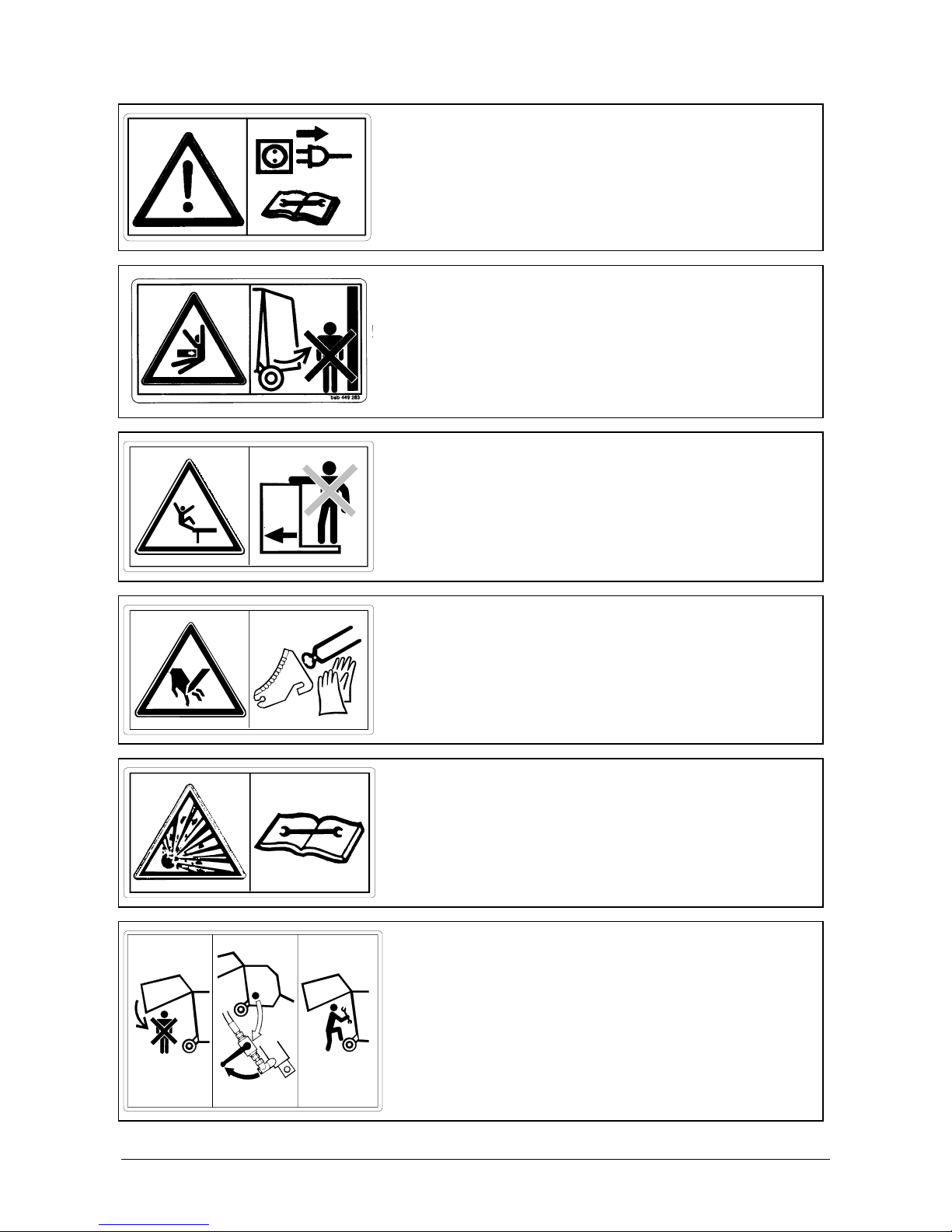
• All the protective devices such as the safety covers, rubber aprons or safety brackets are provided for
your safety! Never operate the baler with defective safety devices or if the safety devices have been
removed!
• Always keep components which are relevant to safety in a suitable condition. All guards must be fitted and
closed before putting the baler into operation!
• Never carry out adjustments, repairs or maintenance and service work on the baler while it is running.
• Always first stop the power take off (pto) shaft, detach the universal drive shaft from the pto shaft stub and
disconnect the electrical connection between the tractor and the baler prior to working on any of the
baler’s moving parts.
• Never try to remove hay, straw or other harvested crop from the baler while it is running. Always first stop
the pto shaft, and switch off the tractor engine.
• While work is in progress, only the driver should be on the tractor. Passengers are not allowed on the
baler!
• Do not climb on the drawbar or other parts of the baler when it is in operation. Also, keep your distance
from the pick-up unit. Do not reach into the working area of the transport units.
• Before threading in the binding material, switch off the baler drive and tractor engine and remove the
ignition key
• All protective guards must be fitted to the baler and must be in sound condition. Before opening the
guards, stop the pto shaft and the tractor engine, remove the ignition key and wait until the baler has
stopped.
• Before detaching the baler from the tractor, secure it with the aid of the chocks to prevent it from rolling
away. Carry the chocks with the baler when the baler is transported or used.
• Upon opening the tailgate, maintain at least 2 metres safety distance from the high voltage cables.
• All maintenance and repair work beyond that described in the descriptions in these operating instructions
must always be carried out by authorised persons. Wear parts of the brake system must always be
replaced on both sides.
• Secure the baler from tipping backwards before detaching the complete pick up unit.
Warning! The baler is inherently dangerous even if all the points listed above are followed exactly. Therefore
always take care when working with the baler to avoid endangering yourself or other people!
2.1. Noise level of tractors and machines
EU Guideline 86-188 - EEC concerning noise at the workplace instructs employers and employees to
measure and control the noise level at the workplace. The noise level during normal field work is subject to
various fluctuations which depend on the noise level of the tractor, and also on the conditions under which the
baler is being used.
The noise level generated by WELGER balers, measured at the driver's head height with the tractor window
open, is less than 70 dB(A) under normal working conditions. The combined noise level generated by the
baler and tractor primarily depends on the level of tractor noise (radios are an additional source of noise). We
recommend that the tractor be driven with the cabin windows closed.

WELGER RP 202 •RP 220 •RP 302 •RP 320 3
2.2. Fire prevention
• Crop materials are very combustible.
• Always keep the baler free of crop remnants and oil
contamination.
• Should overheating of the baler components occur,
determine the cause and resolve accordingly.
• Always keep the electrical circuits of the tractor and baler, as
well as the tractor’s exhaust system in perfect working order.
• The supplied cabling may not be used for purposes other
than for factory installed or approved electrical equipment.
Overloading the electrical cables leads to excessive heating.
• Smoking is forbidden in the vicinity of the baler.
• Always keep a suitable fire extinguisher within easy reach.
2.3. Tailgate safeguard
If maintenance or installation/assembly work is performed
with the tailgate open, it is essential to secure the tailgate to
prevent it from falling.
Use the cut-off valve on the right side of the baler for this
purpose. The shut-off valve may only be actuated from the right
side of the machine.
Return the valve to its original position after completing
maintenance and installation/assembly work (fig. 2).
0388.37.00.00
fig. 1
fig. 2
0387-35
fig. 3

4 WELGER RP 202 •RP 220 •RP 302 •RP 320
2.4. Hydraulic system
Max. operating pressure of the hydraulic system
• 210 bar
When carrying out assembly work on the hydraulic system,
particularly when using accumulators (fig. 4):
• Depressurise the hydraulic system (control valve
set to “Lower”)
• Mechanically secure hydraulically operated
components (pick-up device, cutting unit) to
prevent uncontrolled movements.
According to DIN 20066, the period of use of a hose line,
including any storage period, should not exceed six years.
2.5. Protective guards
In order to comply with European safety regulations EN 704, the
manufacturer of machines is required since 01.01.95 to supply
fixed partitioned protective guards that are self locking but
require the use of a tool to be opened.
In order to open the protective guards on WELGER balers, turn
the hexagon head of the lock anti-clockwise with a 13 mm
spanner and pull the guard off the baler.
Observe the following order:
When opening:..................................first the upper cover (fig. 5).
When closing: ..................................... first the side cover (fig. 6).
To close, push the guard cover against the baler until the lock is
heard engaging.
The baler is never permitted to be operated with the
protective guards open!
fig. 4
fig. 5
fig. 6

WELGER RP 202 •RP 220 •RP 302 •RP 320 5
2.6. Warning symbols
2.6.1. Explanation of the symbols
Danger areas which cannot be made safe by design measures
are identified by yellow warning symbols. Since these are signs
without texts in most cases, their precise meaning is described
below.
The warning symbols must always be kept in a
recognizable state. If there are no warning symbols on your
baler or if they are damaged, replace them (see also Spare
parts list, Section F).
Warning symbol Description/Spare part No.
Read and adhere to the operating manual and safety notes
before starting up for the first time.
Spare part No.: 0388.11.00.00
Close protective guards before putting baler into operation!
Spare part No.: 0389.92.00.00
Never reach into the baler pick-up area as long as the tractor
engine is running with the pto shaft connected.
Spare part No.: 0389.94.00.00
0388.25.00.00 Always switch off the engine and remove the ignition key
before starting any maintenance and repair work.
Spare part No.: 0388.25.00.00

6 WELGER RP 202 •RP 220 •RP 302 •RP 320
Switch off the engine and pull out the plug from the power
supply before starting any repair, maintenance and cleaning
work.
Spare part No.: 0388.13.00.00
Stay clear of tailgate swinging area while in operation.
Spare part No.: 0389.93.00.00
Do not ride on platform or ladder.
Spare part No.: 0391.06.00.00
Handle the cutting unit blades only if you are wearing gloves
and using suitable tools.
Spare part No.: 0387.33.00.00
The accumulator is under gas pressure or oil pressure.
Depressurise the hydraulic system before removal and
repairs.
Spare part No.: 0387.37.00.00
123
0387.34.00.00
Activate the tailgate safeguard before entering the roll
chamber.
Spare part No.: 0387.34.00.00

WELGER RP 202 •RP 220 •RP 302 •RP 320 7
2.6.2. Where to locate the warning signs
0389.93.00.00
0388.11.00.00
0388.37.00.00
0388.25.00.00
0388.24.00.00
0387.34.00.00 0387.34.00.00
0389.92.00.00
0389.92.00.00 0389.92.00.00
0389.94.00.00
0389.94.00.00 0388.13.00.00
0391.06.00.00
0387.33.00.00
0387.37.00.00
1742-73
fig. 7

8 WELGER RP 202 •RP 220 •RP 302 •RP 320
2.7. Symbols for the operation of the baler
The most important operating instructions are shown as symbols for the purpose of clarity. The exact
descriptions are given below.
Symbol Description/Spare part No.
The two lifting eyes in the upper part of the baler are identified
by this symbol.
No other fixing points may be used for hooking up a crane.
Spare part No.: 0389.48.00.00
Locking lever for the cutter blades
To unlock the cutter blades, the lever must be swivelled down
by approx. 90°.
Spare part No.: 0387.31.00.00 and 0387.32.00.00
0387-35
Tailgate safeguard
If the lever is transverse with respect to the flow direction, the
tailgate is secure against lowering.
Spare part No.: 0387.35.00.00
max. 210 bar
0387.36.00.00
Maximum permissible hydraulic pressure
The machine may only be connected to a hydraulic system
which supplies a maximum oil pressure of 210 bar.
Spare part No.: 0387.36.00.00

WELGER RP 202 •RP 220 •RP 302 •RP 320 9
2.8. Proper Use
•The baler has been built exclusively for producing bales
compressed from agricultural straw material lying on the
ground (proper use). Usage beyond this does not constitute
proper use. The manufacturer is not liable for damage
resulting from improper use; the user alone bears the risk.
•Proper use also includes compliance with the operating,
maintenance and servicing conditions specified by the
manufacturer.
•The baler may only be used, maintained and repaired by
persons who are familiar with working with such machines and
who have been informed of the dangers.
•The attachment of auxiliary equipment to the baler, other than
at the factory pre-set positions, is prohibited. Only auxiliary
units approved by the manufacturer may be used.
•The relevant accident prevention regulations, regional safety
standards and other generally recognized safety regulations
are to be observed.
•Unauthorized alterations and the installation of non-approved
parts and equipment on the baler exclude the manufacturer
from any liability or damage resulting from this.
•Alteration of any of the safety relevant components invalidates
both the conformity declaration and the CE-symbol.
2.9. Electromagnetic compatibility (EMC)
The baler is equipped with electronic constituents and
component parts whose function can be influenced by
electromagnetic radiation from other appliances. Such
influences can generate hazards for persons if the following
safety precautions are not taken into account.
In the case of a supplementary installation of electrical and
electronic appliances and/or constituents in the baler with a
connection to the onboard system, the user has to verify
whether the installation causes disturbances to the electronics
of the vehicle or of other constituents.
In particular, it has to be taken into account that any additionally
installed electrical and electronic components comply with the
EMC Directive 89/336/EEC in the respective current version and
that they are CE labeled.

10 WELGER RP 202 •RP 220 •RP 302 •RP 320
2.10. Precautions for driving on the road
Before driving on the road ...
… the baling chamber must be completely emptied (in
accordance with Road Traffic Vehicle Registration
Regulations (RTVRR);
… the baler must be cleared of any harvested crop attached to
it;
… the universal drive shaft must always be fitted to the tractor
pto shaft;
… the tubes of the bale ejector* must be pushed in.
… the lighting equipment of the attached machinery must be
connected to the tractor and its function checked (also in
daylight);
… the support wheels of the pick-up unit must be detached
(working width 2.25 m) and placed in the park position.
Information shall be requested from the manufacturer before the
baler is operated using attached machinery (e.g. bale wrapping
device).
The wheel chocks, which are part of the safety equipment (two
in number), are to be carried on the baler at all times.
The permissible maximum speeds for individual components
(e.g. the drawbar or the axle) do not affect the maximum
permitted speed limit for the entire baler (see Technical Data).
Model-dependent maximum speeds limits have been
exclusively specified in this operating manual. Current relevant
national regulations, which may differ from manufacturers
instructions, are always required to be observed.
Pneumatic braking system*: Do not start driving with an attached baler until both coupling
heads (yellow and red) are connected to the tractor and the
pressure gauge in the tractor cabin indicates the required
operating pressure.
Hydraulic braking system *: Do not start driving with the attached baler until the appropriate
hydraulic hose is connected to the tractor.
Germany (StVZO): Agricultural equipment with a permissible total weight more than
3000 kg are required to have an operating permit. (Technical
changes, e.g. fitting a trailer hook, result in the operating permit
becoming void).
Before making intended changes to the attached working unit, it
is essential to clarify whether the change is permissible without
further requirements and can be entered in the vehicle’s
documents following approval by an officially recognised expert.
Furthermore, the national regulations from the country of use
are to be observed.

WELGER RP 202 •RP 220 •RP 302 •RP 320 11
2.10.1.Details on the rating plate
Item Meaning
1 ID number –individual machine number. Always quote in the event of queries
2 Permissible total weight for operation on public roads. The machine’s actual weight can be less.
3 Permissible axle load for operation on public roads
4 Machine’s year of construction
5 No applicable
6 Trade designation of the machine
7 Details of the systematic structure of the general operating permit (ABE)
8 Max. imposed load on the drawbar eye. The open-type hitch on the tractor must be approved for this
imposed load.
9 Permissible type-related maximum speed of the machine. National regulations can specify a lower
speed!
10 Internal control number
Ident - Nr.
max. Ges. Gewicht/Gross Weight
max. Achslast/Axle Load
Baujahr/Year of Manufacture
max. Stützlast/Imposed Load
Höchstgeschw./max. Speed
Typ Ausführung
1
2
3
4
5
6
7
8
9
10
1742-70
Lely Welger Maschinenfabrik GmbH •Gebrüder-Welger-Str. 3
D - 38304 Wolfenbüttel •Made in Germany
fig. 8

12 WELGER RP 202 •RP 220 •RP 302 •RP 320
3. Component Overview
12V
23 7 6 9
145 108
1741-73
11
fig. 9
No. Component No. Component
1 Pick up unit 7 Net wrapping*
2BALERCONTROL III - Control panel* 8 Bale ejector*
3BALERCONTROL E - Control panel* 9 Tailgate
4 Cutting device* 10 Lock
5 Floor flap* 11 Chain wheels for roller drive
6 Twine wrapping*

WELGER RP 202 •RP 220 •RP 302 •RP 320 13
4. Putting Into Operation
When handling parts of the machine in the area of the drawbar,
make sure that the machine is safeguarded from rolling away.
Do not crank up the support foot until the baler is securely
coupled to the tractor.
Do not disconnect the baler until:
• The surface is level and supports the road wheels and the
support foot
• The baler chamber is empty and the tailgate is closed
• The machine’s road wheels are blocked by chocks
• The hydraulic hoses are depressurised
• There is no load applied to the drawbar eye
Do not step between the tractor and baler until the vehicles are
safeguarded from rolling away by means of the parking brake
and/or the wheel chocks!
Children must be kept away from the baler at all times!
4.1. Attaching the baler
Correct baler attachment and drive shaft set up to the tractor is
important to ensure trouble-free operation of the baler.
After attaching the baler, screw in the support foot with the hand
crank until there is sufficient clearance from the ground.

14 WELGER RP 202 •RP 220 •RP 302 •RP 320
4.1.1. Drawbar configuration
(all dimensions in [mm])
12912912512011947111
A - 3
B - 8
A - 4
B - 7
A - 2
B - 6
A - 1
B - 5
C - 5
1742-53
130
RP 202
A
CB
123
4
87 6 5
fig. 10
A - 1
B - 5
A - 2
B - 6
A - 3
B - 7
A - 4
B - 8
132135127122
120
105
110
RP 302
1741-108
C - 5
130
A
CB
1234
87 6 5
fig. 11

WELGER RP 202 •RP 220 •RP 302 •RP 320 15
1724-53
1
5
2
6
3
7
4
120
100
115
250
100
130
RP 220
RP 320
13
57
2
4
6
fig. 12
4.1.2. Adjusting the trailer hitch
Any adjustment in the height set-up, and therefore a
displacement in the drawbar eye position, shall only be carried
out by the manufacturer or an approved specialist workshop.
• Position the baler on even ground.
• Screw out the support foot until the baler is standing level.
Use the flange plate on the stand as a reference.
• Measure the height of the tractor towing hitch;
• Measure the height of the baler drawbar eye.
• With reference to Figure 10 to Figure 12 align the drawbar
with the hole configuration that gives the closest fit to the
desired dimension. The locking nuts must be replaced by
new ones each time they are undone.
• After aligning the trailor hitch, the drawbar eye needs to be
brought into a horizontal position. Do this by undoing the
fastening screws of the drawbar eye and correct the
alignment of the drawbar eye with the help of the threaded
pin.
fig. 13
fig. 14

16 WELGER RP 202 •RP 220 •RP 302 •RP 320
Important: Depending on the equipment configuration, a rigid
or rotatable drawbar eye can be fitted. (observe local
regulations!) The drawbar eye [3] can be rotated about its
longitudinal axis, but has to be locked for a open-type hitch
attachment
For open-type hitch (high hitch) attachment, prevent
drawbar eye [3] from turning by fitting parts 4, 5 and 6.
For tow hitch (low hitch) attachment, do not prevent drawbar eye
[3] from moving, i.e., parts 4 - 6 not be fitted. Parts 4 –6 are
included loose with the delivery of balers having rotating
drawbar eyes.
The horizontal protective blacket underneath the drawbar must
be set for a minimum ground clearance of 50 cm.
Note: All fastening screws and nuts must be done up tightly:
Component see…Tension
moment
Bracket,
(RP 202 / RP 302)
Fig 13 270 Nm
Bracket, strengthened Fig. 14 450 Nm
Drawbar eye Fig. 15 and Fig 16,
Pos. 1
350 Nm
Table 2: Tension moment
1725-159
1
2654
3
D7
fig. 15
D8
1
3
4
5
6
2
1724-54
fig. 16
This manual suits for next models
13
Table of contents
Other LELY WELGER Farm Equipment manuals
Popular Farm Equipment manuals by other brands

Agrimate
Agrimate AM-RT-212-7P user manual

Topcon
Topcon MACHINE CONTROL AG System Five Operator's manual

enorossi
enorossi RAKE CADDY Series User and maintenance manual

Rosensteiner
Rosensteiner BULL TOP S Operation and maintenance manual

Bridgeview
Bridgeview BALE KING 7400 Operator's manual

MacDon
MacDon C Series Operator's manual