manuals.online logo
Brands
  1. Home
  2. •
  3. Brands
  4. •
  5. LELY WELGER
  6. •
  7. Farm Equipment
  8. •
  9. LELY WELGER RP 245 User manual

LELY WELGER RP 245 User manual

Other LELY WELGER Farm Equipment manuals

LELY WELGER RP 405 User manual

LELY WELGER

LELY WELGER RP 405 User manual

LELY WELGER RPC 445 TORNADO User manual

LELY WELGER

LELY WELGER RPC 445 TORNADO User manual

LELY WELGER RP 202 CLASSIC User manual

LELY WELGER

LELY WELGER RP 202 CLASSIC User manual

Popular Farm Equipment manuals by other brands

Schaffert Rebounder Mounting instructions

Schaffert

Schaffert Rebounder Mounting instructions

Stocks AG Fan Jet Pro Plus 65 Original Operating Manual and parts list

Stocks AG

Stocks AG Fan Jet Pro Plus 65 Original Operating Manual and parts list

Cumberland Integra Feed-Link Installation and operation manual

Cumberland

Cumberland Integra Feed-Link Installation and operation manual

BROWN BDHP-1250 Owner's/operator's manual

BROWN

BROWN BDHP-1250 Owner's/operator's manual

Molon BCS operating instructions

Molon

Molon BCS operating instructions

Vaderstad Rapid Series instructions

Vaderstad

Vaderstad Rapid Series instructions

HighLine BM1400 operating manual

HighLine

HighLine BM1400 operating manual

GSi PNEG-2314 installation manual

GSi

GSi PNEG-2314 installation manual

Checchi & Magli TEXDRIVE owner's manual

Checchi & Magli

Checchi & Magli TEXDRIVE owner's manual

Amazone Cenius 4003-2TX operating manual

Amazone

Amazone Cenius 4003-2TX operating manual

MASSEY FERGUSON MF 9313S Operator's manual

MASSEY FERGUSON

MASSEY FERGUSON MF 9313S Operator's manual

Cima BLITZ Maintenance Instruction

Cima

Cima BLITZ Maintenance Instruction

Amazone CombiDisc 3000 Original operating manual

Amazone

Amazone CombiDisc 3000 Original operating manual

HE-VA Disc-Roller XL Contour Operating instructions/spare parts list

HE-VA

HE-VA Disc-Roller XL Contour Operating instructions/spare parts list

AGT AGT-SSFM product manual

AGT

AGT AGT-SSFM product manual

Milestone 72-84 manual

Milestone

Milestone 72-84 manual

KUHN Hector 3000 Complementary instructions

KUHN

KUHN Hector 3000 Complementary instructions

Krone X-Disc 6200 operating instructions

Krone

Krone X-Disc 6200 operating instructions

manuals.online logo
manuals.online logoBrands
  • About & Mission
  • Contact us
  • Privacy Policy
  • Terms and Conditions

Copyright 2025 Manuals.Online. All Rights Reserved.

LELY WELGER
RP 245
RP 245
1745.99.03.0311.10(Translationoftheoriginalmanual)
OperatingManual
4 WELGER RP 245
TABLE OF CONTENTS
1. TYPE OVERVIEW ...............................................................................................................................................7
2. IT IS FOR YOUR SAFETY..................................................................................................................................8
2.1. General safety instructions.....................................................................................................................8
2.2. Noise level of tractors and machines .....................................................................................................9
2.3. Fire prevention .....................................................................................................................................10
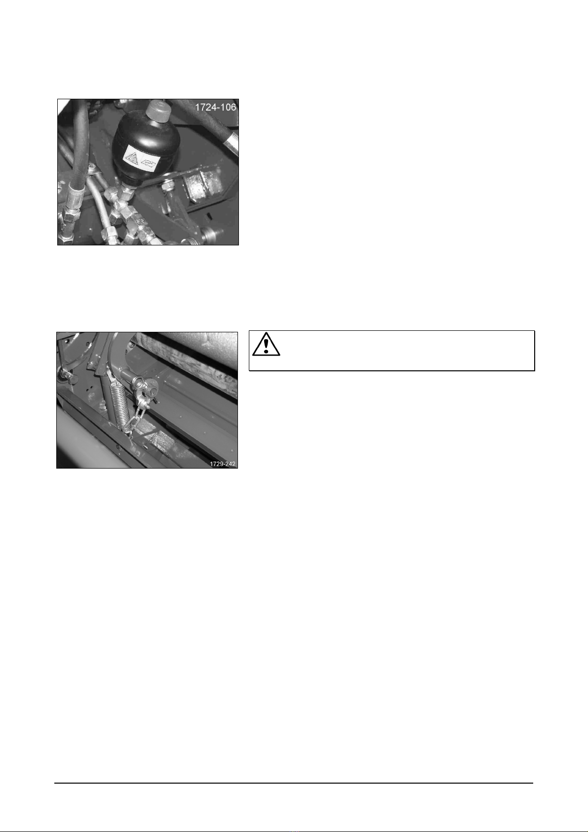
2.4. Tail gate safeguard...............................................................................................................................10
2.5. Net knife safeguard ..............................................................................................................................11
2.6. Guard casings ......................................................................................................................................12
2.7. Maintenance Platform and Ladder .......................................................................................................12
2.8. Symbols in this manual ........................................................................................................................13
2.9. Warning symbols at the machine .........................................................................................................14
2.10. Text-free operating instructions at the machine.................................................................................16
2.11. Proper use..........................................................................................................................................17
2.12. Foreseeable misuse...........................................................................................................................17
2.13. Electromagnetic compatibility (EMC) .................................................................................................18
2.14. To heed in the road traffic ..................................................................................................................18
3. OVERVIEW OF THE ASSEMBLY GROUPS ...................................................................................................22
3.1. Machine ................................................................................................................................................22
3.2. Control..................................................................................................................................................23
3.3. Protection of the control unit ................................................................................................................24
3.4. Set machine type (Balercontrol E) .......................................................................................................24
3.5. Set machine type (E-Link)....................................................................................................................24
4. START UP.........................................................................................................................................................25
4.1. Attach baler ..........................................................................................................................................25
4.2. Drive shaft ............................................................................................................................................30
4.3. Net knife safeguard ..............................................................................................................................32
4.4. Hydraulic connections ..........................................................................................................................32
4.5. Electrical system ..................................................................................................................................35
4.6. Compressed-air braking system ..........................................................................................................36
4.7. Hydraulic braking system .....................................................................................................................37
5. TWINE TYING*..................................................................................................................................................38
5.1. Thread twine.........................................................................................................................................38
5.2. Binding bar ...........................................................................................................................................40
5.3. Adjusting the twine brake .....................................................................................................................41
5.4. Further settings ....................................................................................................................................42
6. NET TYING* ......................................................................................................................................................43
6.1. Inserting the net....................................................................................................................................43
6.2. Tighten net knife...................................................................................................................................48
6.3. Setting of net layers..............................................................................................................................48
7. CUTTING DEVICE*...........................................................................................................................................49
7.1. Equipment ............................................................................................................................................49
7.2. Knife groups .........................................................................................................................................49
7.3. Moving in and out the cutting device....................................................................................................52
7.4. Lock bottom door..................................................................................................................................64
7.5. Brittle crop material ..............................................................................................................................65
7.6. Assembly and disassembly of the cutting device knives .....................................................................65
7.7. Regrinding the cutting device knives....................................................................................................66
WELGER RP 245 5
8. FIELD USE ........................................................................................................................................................67
8.1. Driving on the road ...............................................................................................................................68
8.2. Bale ejector* .........................................................................................................................................68
8.3. Laying swaths.......................................................................................................................................68
8.4. Pick-up..................................................................................................................................................69
8.5. Feed guide plate...................................................................................................................................71
8.6. PTO speed ...........................................................................................................................................71
8.7. Driving style..........................................................................................................................................71
8.8. Setting the bale density ........................................................................................................................72
8.9. Setting of net layers..............................................................................................................................72
8.10. Operate tail gate.................................................................................................................................73
9. OPERATION / TYING .......................................................................................................................................75
9.1. Control box BALERCONTROL E .........................................................................................................75
9.2. E-LINK control box ...............................................................................................................................79
9.3. Eject bales............................................................................................................................................84
10. SAFETY CLUTCH / REVERSING UNIT.........................................................................................................85
10.1. Drive shaft with shear bolt yoke*........................................................................................................85
10.2. Drive shaft with cam-type cut-out clutch* ...........................................................................................85
10.3. Reverse main drive ............................................................................................................................85
10.4. Hydraulic bottom door*.......................................................................................................................86
11. MAINTENANCE / SETTING ...........................................................................................................................90
11.1. General notes.....................................................................................................................................90
11.2. Environment/Disposal ........................................................................................................................90
11.3. Tensioners..........................................................................................................................................90
11.4. Maintenance of the net tying unit .......................................................................................................91
11.5. Emergency operation of the tying unit................................................................................................92
11.6. Components for Balercontrol .............................................................................................................96
11.7. Hydraulic layouts ................................................................................................................................99
11.8. Setting the sensors* .........................................................................................................................102
11.9. Short check E-LINK..........................................................................................................................103
11.10. Pin assignment E-LINK ..................................................................................................................104
11.11. Pin assignment BALERCONTROL E.............................................................................................105
11.12. Chain lubrication (oil lubrication)....................................................................................................106
11.13. Roller lubrication (grease lubrication) ............................................................................................107
11.14. Grease knife lever ..........................................................................................................................107
11.15. Lubrication chart.............................................................................................................................108
11.16. Schematic presentation of the lubrication points ...........................................................................109
11.17. Adjusting the deflectors..................................................................................................................110
11.18. Tensioning the roller chains ...........................................................................................................111
11.19. Winter pause..................................................................................................................................112
11.20. Tires and Tire pressure ..................................................................................................................113
12. TECHNICAL DATA.......................................................................................................................................114
12.1. Overview ..........................................................................................................................................114
12.2. Dimensions.......................................................................................................................................115
WELGER RP 245 11
2.4.1. Hydraulic System
Max. operating pressure of the hydraulic system:
• 210 bar
During assembly work on the hydraulic system, in particular if
accumulators are used (Figure 4):
• Depressurize hydraulic system
(control unit to "Lower")
• Secure hydraulic operated parts (pick-up, cutting device)
mechanically against unexpected movements.
According to DIN 20066 must hoses not be older than six years,
including storage time.
2.5. Net knife safeguard
Attention, risk of injury by cutting! During work in the
vicinity of the net knife: fit net knife safeguard.
When maintenance or assembly work is performed in the
vicinity of the net knife, the net knife must be mechanically
secured to prevent unintentional falling-down:
(Figure 5) insert and secure safety chain with spring clip.
After termination of maintenance and assembly work: remove
net knife safeguard.
Figure 4
Figure 5
12 WELGER RP 245
2.6. Guard casings
To open the guard casings on the machine, turn the catches
concerned with a 13 mm spanner slightly in counter clockwise
direction and pull off the guard casing from the machine.
 Catches at the left and right guard casing: Figure 6
 Catches at the front guard casing: Figure 7
For closing press the guard casing against the machine until
the locking of the catches can be heard.
Attention, danger of injury! Never operate the machine
with open guard casings!
2.7. Maintenance Platform and Ladder
Attention, danger of falling! Never step onto the
maintenance platform (Figure 8), while the machine is in
motion. Before stepping onto the maintenance platform: stop
machine, switch-off power take-off shaft and tractor motor and
wait for standstill of the machine.
Step only via the ladder onto the maintenance platform and
leave it the same way. Never step onto the hinged up ladder –
always hinge down ladder prior to enter it.
To step onto the maintenance platform: Unlock and hinge down
the ladder (Figure 9).
Before machine can move on: Hinge up ladder (Figure 9) and
lock it.
Figure 6
Figure 7
Figure 8
Figure 9