JJ
JJ
J 1010
1010
10
Spare Part List (ACTIVE VERSIONS)Spare Part List (ACTIVE VERSIONS)
Spare Part List (ACTIVE VERSIONS)Spare Part List (ACTIVE VERSIONS)
Spare Part List (ACTIVE VERSIONS)
Code Description
AccessoriesAccessories
AccessoriesAccessories
Accessories
277334 Owner’s Manual
130274 Mains Cable (EU)
130276 Mains Cable (US)
AV-12AAV-12A
AV-12AAV-12A
AV-12A
Amplifier AssemblyAmplifier Assembly
Amplifier AssemblyAmplifier Assembly
Amplifier Assembly
737103737103
737103737103
737103 200W Amplifier Module (EU)200W Amplifier Module (EU)
200W Amplifier Module (EU)200W Amplifier Module (EU)
200W Amplifier Module (EU)
737104737104
737104737104
737104 200W Amplifier Module (US)200W Amplifier Module (US)
200W Amplifier Module (US)200W Amplifier Module (US)
200W Amplifier Module (US)
778146 * Amplifier Cables Assembly
768211768211
768211768211
768211 **
**
*200W Supply Board (Pcb#313061)200W Supply Board (Pcb#313061)
200W Supply Board (Pcb#313061)200W Supply Board (Pcb#313061)
200W Supply Board (Pcb#313061)
340079 ** TO220 Mica Washer
340078 ** TO220 Insulated Bush
140081 ** H 2c P=10 Terminal Block
140069 ** H 3c P=10mm Terminal Block
110119 ** Fuse Clip 10A max (EU) (US)
100060 ** 7815 +15V 1A Voltage Regulator
100049 ** 7915 -15V 1A Voltage Regulator
080605 ** KBL02 4A 200V Rectifier Diode Bridge
080156 ** 1N4002 1A 100V Rectifier Diode
030560 ** 4700u 80v 20% Snap-In Electrolytic Capacitor
030526 ** 2200u 35v 20% Snap-In Electrolytic Capacitor
020250 ** 10n 400V 10% MKT Polyester Capacitor
768207768207
768207768207
768207 **
**
*Inputs Board (Pcb#313058)Inputs Board (Pcb#313058)
Inputs Board (Pcb#313058)Inputs Board (Pcb#313058)
Inputs Board (Pcb#313058)
141189 ** Hor Female XLR-Jack Socket (NCJ6FK-H Neutrik)
141186 ** Hor Male XLR Socket (NC3MAH Neutrik)
140929 ** 9 Contacts Vert Male Connector
120857 ** Vertical Male Faston 6.3mm
110267 ** 1sw 2pos Horizontal Slider Switch
100061 ** TL072 Dual J-Fet Operational Amplifier
080743 ** 3mm Wide Diffused Green Led
080742 ** Led 3mm Wide Diffused Red-Grn
080293 ** 15V 1W 5% Zener Diode
074570 ** 5K 31steps Linear Potentiometer
070245 ** 100K 20% Vertical Linear Trimmer
042706 ** 80K6 1/4W 1% Metalized Film Resistor
042630 ** 17K4 1/4W 1% Metalized Film Resistor
042625 ** 15K0 1/4W 1% Metalized Film Resistor
020250 ** 10n 400V 10% MKT Polyester Capacitor
727606727606
727606727606
727606 **
**
*200W Amplifier Board (Pcb#319064)200W Amplifier Board (Pcb#319064)
200W Amplifier Board (Pcb#319064)200W Amplifier Board (Pcb#319064)
200W Amplifier Board (Pcb#319064)
768214 ** 200W Amplifier Board (Pcb#319064) without Power Transistors
141102 *** 6 Contacts Vert Male Connector
140929 *** 9 Contacts Vert Male Connector
110316 *** Relay 24V / 1 Switch no 16A 250V
100904 *** LM393 Dual Comparator
100061 *** TL072 Dual J-Fet Operational Amplifier
090917 *** MJE350 TO126 Pnp Transistor
090916 *** MJE340 TO126 Npn Transistor
090201 *** 2N5401 TO92 Pnp Transistor
090200 *** 2N5550 TO92 Npn Transistor
090194 *** BC560 TO92 LN Pnp Transistor
090183 *** BC550 TO92 LN Npn Transistor
090153 *** BC327 TO92 Pnp Transistor
080901 *** VTL5C4 Analog Optoisolator
080245 *** 7V5 1W 5% Zener Diode
080171 *** FE6B 6A 100V Fast Recovery Diode
080156 *** 1N4002 1A 100V Rectifier Diode
080103 *** 1N4148 100mA 75V Signal Diode
070105 *** 470E 20% Vertical Linear Trimmer
060591 *** 8K2 2W 10% Resistor
060051 *** 0E22 5W 5% Wire Resistor
042695 *** 56K2 1/4W 1% Metalized Film Resistor
042685 *** 47K5 1/4W 1% Metalized Film Resistor
042605 *** 10K0 1/4W 1% Metalized Film Resistor
030715 *** 1000u 6v3 20% Vert Electrolytic Capacitor
340154 ** TO3/TO218 Mica Washer
340079 ** TO220 Mica Washer
340078 ** TO220 Insulated Bush
090920 ** MJE802 TO126 Npn Darl Transistor
090919 ** MJE15031 TO220 Pnp Transistor
090918 ** MJE15030 TO220 Npn Transistor
090913 ** MJE4352 TO218 Pnp Transistor
090912 ** MJE4342 TO218 Npn Transistor
090863 ** TIP36C TO218 Pnp Transistor
090862 ** TIP35C TO218 Npn Transistor
080821 ** Ptc 90 PTH59F04BE222TS
667697 * Rear Panel
237077237077
237077237077
237077 **
**
*Transformer 230Vac 200W (EU)Transformer 230Vac 200W (EU)
Transformer 230Vac 200W (EU)Transformer 230Vac 200W (EU)
Transformer 230Vac 200W (EU)
237078237078
237078237078
237078 **
**
*Transformer 115Vac 200W (US)Transformer 115Vac 200W (US)
Transformer 115Vac 200W (US)Transformer 115Vac 200W (US)
Transformer 115Vac 200W (US)
210215 * Adhesive Rubber Foam 10x1.9mm (Specify mt)
210212 * Slider Switch Adhesive Gasket
110614 * Mains Socket
110291 * Power Switch
110029 * T4A Fuse 5x20mm (EU)
110014 * T2.5A Fuse 5x20mm (EU)
110036 * T4A Fuse 6.3x32mm (US)
110035 * T2.5A Fuse 6.3x32mm (US)
080607 * KBPC25 25A 200V Rectifier Diode Bridge
020491 * 100nF 10% 250Vac Polyester Capacitor
Box AssemblyBox Assembly
Box AssemblyBox Assembly
Box Assembly
778112 Cables Assembly
768202768202
768202768202
768202 Crossover Filter Board (Pcb#313063) AV-12/4 OhmCrossover Filter Board (Pcb#313063) AV-12/4 Ohm
Crossover Filter Board (Pcb#313063) AV-12/4 OhmCrossover Filter Board (Pcb#313063) AV-12/4 Ohm
Crossover Filter Board (Pcb#313063) AV-12/4 Ohm
667702 Handle
667700 Grid
659027 White Pot Knob
657271 Box
657270 EWT(TM) Elliptical Horn
229037229037
229037229037
229037 1" 4ohm Horn Tweeter1" 4ohm Horn Tweeter
1" 4ohm Horn Tweeter1" 4ohm Horn Tweeter
1" 4ohm Horn Tweeter
227056227056
227056227056
227056 12" 4ohm Woofer Speaker12" 4ohm Woofer Speaker
12" 4ohm Woofer Speaker12" 4ohm Woofer Speaker
12" 4ohm Woofer Speaker
210242 Filler for Speaker Box (Specify m²)
210217 Black Sealer (specify mt)
210215 Adhesive Rubber Foam 10x1.9mm (Specify mt)
210211 Gasket between Tweeter and Horn
120964 M4i M5e x17.5mm Threaded Pin
120148 Screw M5x65mm for Handle
120147 Screw M4x8mm for Speakers
AV-15AAV-15A
AV-15AAV-15A
AV-15A
Amplifier AssemblyAmplifier Assembly
Amplifier AssemblyAmplifier Assembly
Amplifier Assembly
737105737105
737105737105
737105 350W Amplifier Module (EU)350W Amplifier Module (EU)
350W Amplifier Module (EU)350W Amplifier Module (EU)
350W Amplifier Module (EU)
737106737106
737106737106
737106 350W Amplifier Module (US)350W Amplifier Module (US)
350W Amplifier Module (US)350W Amplifier Module (US)
350W Amplifier Module (US)
778146 * Amplifier Cables Assembly
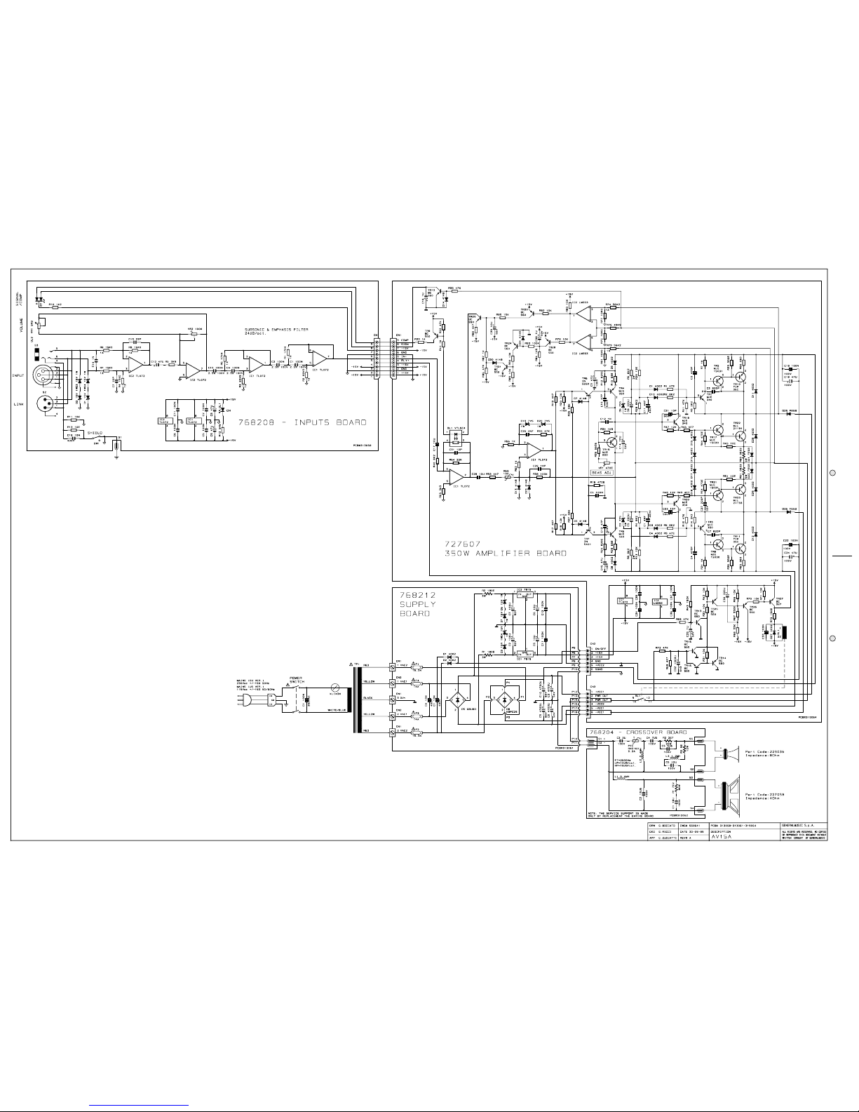
768212768212
768212768212
768212 **
**
*350W Supply Board (Pcb#313061)350W Supply Board (Pcb#313061)
350W Supply Board (Pcb#313061)350W Supply Board (Pcb#313061)
350W Supply Board (Pcb#313061)
340079 ** TO220 Mica Washer
340078 ** TO220 Insulated Bush
140081 ** H 2c P=10 Terminal Block
140069 ** H 3c P=10mm Terminal Block
110119 ** Fuse Clip 10A max (EU) (US)
100060 ** 7815 +15V 1A Voltage Regulator
100049 ** 7915 -15V 1A Voltage Regulator
080606 ** GBU8D 8A Rectifier Diodes Bridge
080293 ** 15V 1W 5% Zener Diode
080156 ** 1N4002 1A 100V Rectifier Diode
060403 ** 180E 3W 10% Resistor
030560 ** 4700u 80v 20% Snap-In Electrolytic Capacitor
030555 ** 4700u 50V 20% Snap-In Electrolytic Capacitor
768208768208
768208768208
768208 **
**
*Inputs Board (Pcb#313058)Inputs Board (Pcb#313058)
Inputs Board (Pcb#313058)Inputs Board (Pcb#313058)
Inputs Board (Pcb#313058)
141189 ** Hor Female XLR-Jack Socket (NCJ6FK-H Neutrik)
141186 ** Hor Male XLR Socket (NC3MAH Neutrik)
140929 ** 9 Contacts Vert Male Connector
120857 ** Vertical Male Faston 6.3mm
110267 ** 1sw 2pos Horizontal Slider Switch
100061 ** TL072 Dual J-Fet Operational Amplifier
080743 ** 3mm Wide Diffused Green Led
080742 ** Led 3mm Wide Diffused Red-Grn
080293 ** 15V 1W 5% Zener Diode
074570 ** 5K 31steps Linear Potentiometer
070245 ** 100K 20% Vertical Linear Trimmer
042715 ** 82K5 1/4W 1% Metalized Film Resistor
042630 ** 17K4 1/4W 1% Metalized Film Resistor
042625 ** 15K0 1/4W 1% Metalized Film Resistor
727607727607
727607727607
727607 **
**
*350W Amplifier Board (Pcb#319064)350W Amplifier Board (Pcb#319064)
350W Amplifier Board (Pcb#319064)350W Amplifier Board (Pcb#319064)
350W Amplifier Board (Pcb#319064)
768215 ** 350W Amplifier Board (Pcb#319064) without Power Transistors
141102 *** 6 Contacts Vert Male Connector
140929 *** 9 Contacts Vert Male Connector
110316 *** Relay 24V / 1 Switch no 16A 250V
100904 *** LM393 Dual Comparator
100061 *** TL072 Dual J-Fet Operational Amplifier
090917 *** MJE350 TO126 Pnp Transistor
090916 *** MJE340 TO126 Npn Transistor
090201 *** 2N5401 TO92 Pnp Transistor
090200 *** 2N5550 TO92 Npn Transistor
090194 *** BC560 TO92 LN Pnp Transistor
090183 *** BC550 TO92 LN Npn Transistor
090153 *** BC327 TO92 Pnp Transistor
080901 *** VTL5C4 Analog Optoisolator
080245 *** 7V5 1W 5% Zener Diode
080171 *** FE6B 6A 100V Fast Recovery Diode
080156 *** 1N4002 1A 100V Rectifier Diode
080103 *** 1N4148 100mA 75V Signal Diode
070105 *** 470E 20% Vertical Linear Trimmer
060591 *** 8K2 2W 10% Resistor
060051 *** 0E22 5W 5% Wire Resistor
042695 *** 56K2 1/4W 1% Metalized Film Resistor
042687 *** 49K9 1/4W 1% Metalized Film Resistor
042605 *** 10K0 1/4W 1% Metalized Film Resistor
030715 *** 1000u 6v3 20% Vert Electrolytic Capacitor
340783 ** TO264 Mica Washer
340154 ** TO3/TO218 Mica Washer
340079 ** TO220 Mica Washer
340078 ** TO220 Insulated Bush
090924 ** MJL21194 TO264 Npn Transistor
090923 ** MJL21193 TO264 Pnp Transistor
090920 ** MJE802 TO126 Npn Darl Transistor
090919 ** MJE15031 TO220 Pnp Transistor
090918 ** MJE15030 TO220 Npn Transistor
090863 ** TIP36C TO218 Pnp Transistor
090862 ** TIP35C TO218 Npn Transistor
080821 ** Ptc 90 PTH59F04BE222TS
667698 * Rear Panel
237068237068
237068237068
237068 **
**
*Transformer 230Vac 350W (EU)Transformer 230Vac 350W (EU)
Transformer 230Vac 350W (EU)Transformer 230Vac 350W (EU)
Transformer 230Vac 350W (EU)
237069237069
237069237069
237069 **
**
*Transformer 115Vac 350W (US)Transformer 115Vac 350W (US)
Transformer 115Vac 350W (US)Transformer 115Vac 350W (US)
Transformer 115Vac 350W (US)
210215 * Adhesive Rubber Foam 10x1.9mm (Specify mt)
210212 * Slider Switch Adhesive Gasket
110614 * Mains Socket
110291 * Power Switch
110029 * T4A Fuse 5x20mm (EU)
110018 * T6.3A Fuse 5x20mm (EU)
110037 * T6.3A Fuse 6.3x32mm (US)
110036 * T4A Fuse 6.3x32mm (US)
080607 * KBPC25 25A 200V Rectifier Diode Bridge
020491 * 100nF 10% 250Vac Polyester Capacitor
Box AssemblyBox Assembly
Box AssemblyBox Assembly
Box Assembly
778112 Cables Assembly
768204768204
768204768204
768204 Crossover Filter Board (Pcb#313062) AV-15/4 OhmCrossover Filter Board (Pcb#313062) AV-15/4 Ohm
Crossover Filter Board (Pcb#313062) AV-15/4 OhmCrossover Filter Board (Pcb#313062) AV-15/4 Ohm
Crossover Filter Board (Pcb#313062) AV-15/4 Ohm
667703 Handle
667701 Grid
659027 White Pot Knob
657272 Box
657270 EWT(TM) Elliptical Horn
229036229036
229036229036
229036 1" 8ohm Horn Compression Driver1" 8ohm Horn Compression Driver
1" 8ohm Horn Compression Driver1" 8ohm Horn Compression Driver
1" 8ohm Horn Compression Driver
227058227058
227058227058
227058 15" 4ohm Woofer Speaker15" 4ohm Woofer Speaker
15" 4ohm Woofer Speaker15" 4ohm Woofer Speaker
15" 4ohm Woofer Speaker
210242 Filler for Speaker Box (Specify m²)
210217 Black Sealer (specify mt)
210215 Adhesive Rubber Foam 10x1.9mm (Specify mt)
210211 Gasket between Tweeter and Horn
120965 M4i M5e x24mm Threaded Pin
120148 Screw M5x65mm for Handle
120147 Screw M4x8mm for Speakers
AV-15SAAV-15SA
AV-15SAAV-15SA
AV-15SA
Amplifier AssemblyAmplifier Assembly
Amplifier AssemblyAmplifier Assembly
Amplifier Assembly
737107737107
737107737107
737107 350W Amplifier Module (EU)350W Amplifier Module (EU)
350W Amplifier Module (EU)350W Amplifier Module (EU)
350W Amplifier Module (EU)
737108737108
737108737108
737108 350W Amplifier Module (US)350W Amplifier Module (US)
350W Amplifier Module (US)350W Amplifier Module (US)
350W Amplifier Module (US)
778147 * Amplifier Cables Assembly
768213768213
768213768213
768213 **
**
*350W Supply Board (Pcb#313061)350W Supply Board (Pcb#313061)
350W Supply Board (Pcb#313061)350W Supply Board (Pcb#313061)
350W Supply Board (Pcb#313061)
340079 ** TO220 Mica Washer
340078 ** TO220 Insulated Bush
100060 ** 7815 +15V 1A Voltage Regulator
100049 ** 7915 -15V 1A Voltage Regulator
080606 ** GBU8D 8A Rectifier Diodes Bridge
080293 ** 15V 1W 5% Zener Diode
080156 ** 1N4002 1A 100V Rectifier Diode
060403 ** 180E 3W 10% Resistor
030884 ** 10000U 80V 20% Snap-In Electrolytic Capacitor
030555 ** 4700u 50V 20% Snap-In Electrolytic Capacitor
768210 * Controls & Crossover Board (Pcb#313060)
140929 ** 9 Contacts Vert Male Connector
140908 ** 6 Contacts Vert Male Small Connector
140873 ** 4 Contacts Vert Male Connector
110305 ** Relay 12V / 2 Switch 1A 250V
100919 ** MC33078 Dual LN Operational Amplifier
100084 ** TL074 Quad J-Fet Operational Amplifier
100061 ** TL072 Dual J-Fet Operational Amplifier
100019 ** TL071 LN J-Fet Operational Amplifier
080743 ** 3mm Wide Diffused Green Led
080742 ** Led 3mm Wide Diffused Red-Grn
080103 ** 1N4148 100mA 75V Signal Diode
075820 ** 4x100K 16mm Hor Rotary Alog Potentiometer
074570 ** 5K 31steps Linear Potentiometer
070241 ** 100K 20% Horizontal Linear Trimmer
042717 ** 88K7 1/4W 1% Metalized Film Resistor
042625 ** 15K0 1/4W 1% Metalized Film Resistor
042617 ** 13K0 1/4W 1% Metalized Film Resistor
042605 ** 10K0 1/4W 1% Metalized Film Resistor
042565 ** 4K99 1/4W 1% Metalized Film Resistor
042555 ** 4K22 1/4W 1% Metalized Film Resistor
768209768209
768209768209
768209 **
**
*Inputs Board (Pcb#313059)Inputs Board (Pcb#313059)
Inputs Board (Pcb#313059)Inputs Board (Pcb#313059)
Inputs Board (Pcb#313059)
141189 ** Hor Female XLR-Jack Socket (NCJ6FK-H Neutrik)
141186 ** Hor Male XLR Socket (NC3MAH Neutrik)
140935 ** 6 Contacts Hor Male Connector
140872 ** 4 Contatcs Hor Male Connector
110267 ** 1sw 2pos Horizontal Slider Switch
080293 ** 15V 1W 5% Zener Diode
727607727607
727607727607
727607 **
**
*350W Amplifier Board (Pcb#319064)350W Amplifier Board (Pcb#319064)
350W Amplifier Board (Pcb#319064)350W Amplifier Board (Pcb#319064)
350W Amplifier Board (Pcb#319064)
768215 ** 350W Amplifier Board (Pcb#319064) without Power Transistors
141102 *** 6 Contacts Vert Male Connector
140929 *** 9 Contacts Vert Male Connector
110316 *** Relay 24V / 1 Switch no 16A 250V
100904 *** LM393 Dual Comparator
100061 *** TL072 Dual J-Fet Operational Amplifier
090917 *** MJE350 TO126 Pnp Transistor
090916 *** MJE340 TO126 Npn Transistor
090201 *** 2N5401 TO92 Pnp Transistor
090200 *** 2N5550 TO92 Npn Transistor
090194 *** BC560 TO92 LN Pnp Transistor
090183 *** BC550 TO92 LN Npn Transistor
090153 *** BC327 TO92 Pnp Transistor
080901 *** VTL5C4 Analog Optoisolator
080245 *** 7V5 1W 5% Zener Diode
080171 *** FE6B 6A 100V Fast Recovery Diode
080156 *** 1N4002 1A 100V Rectifier Diode
080103 *** 1N4148 100mA 75V Signal Diode
070105 *** 470E 20% Vertical Linear Trimmer
060591 *** 8K2 2W 10% Resistor
060051 *** 0E22 5W 5% Wire Resistor
042695 *** 56K2 1/4W 1% Metalized Film Resistor
042687 *** 49K9 1/4W 1% Metalized Film Resistor
042605 *** 10K0 1/4W 1% Metalized Film Resistor
030715 *** 1000u 6v3 20% Vert Electrolytic Capacitor
340783 ** TO264 Mica Washer
340154 ** TO3/TO218 Mica Washer
340079 ** TO220 Mica Washer
340078 ** TO220 Insulated Bush
090924 ** MJL21194 TO264 Npn Transistor
090923 ** MJL21193 TO264 Pnp Transistor
090920 ** MJE802 TO126 Npn Darl Transistor
090919 ** MJE15031 TO220 Pnp Transistor
090918 ** MJE15030 TO220 Npn Transistor
090863 ** TIP36C TO218 Pnp Transistor
090862 ** TIP35C TO218 Npn Transistor
080821 ** Ptc 90 PTH59F04BE222TS
667699 * Rear Panel
237068237068
237068237068
237068 **
**
*Transformer 230Vac 350W (EU)Transformer 230Vac 350W (EU)
Transformer 230Vac 350W (EU)Transformer 230Vac 350W (EU)
Transformer 230Vac 350W (EU)
237069237069
237069237069
237069 **
**
*Transformer 115Vac 350W (US)Transformer 115Vac 350W (US)
Transformer 115Vac 350W (US)Transformer 115Vac 350W (US)
Transformer 115Vac 350W (US)
210215 * Adhesive Rubber Foam 10x1.9mm (Specify mt)
210212 * Slider Switch Adhesive Gasket
110614 * Mains Socket
110291 * Power Switch
110029 * T4A Fuse 5x20mm (EU)
110018 * T6.3A Fuse 5x20mm (EU)
110037 * T6.3A Fuse 6.3x32mm (US)
110036 * T4A Fuse 6.3x32mm (US)
080607 * KBPC25 25A 200V Rectifier Diode Bridge
020491 * 100nF 10% 250Vac Polyester Capacitor
Box AssemblyBox Assembly
Box AssemblyBox Assembly
Box Assembly
667703 Handle
667701 Grid
659027 White Pot Knob
659026 Orange Pot Knob
657273 Box
347393 Threaded Clog (to steady on the floor)
227060227060
227060227060
227060 15" 4ohm Woofer Speaker15" 4ohm Woofer Speaker
15" 4ohm Woofer Speaker15" 4ohm Woofer Speaker
15" 4ohm Woofer Speaker
210242 Filler for Speaker Box (Specify m²)
210217 Black Sealer (specify mt)
210215 Adhesive Rubber Foam 10x1.9mm (Specify mt)
177721 Fixing Plate (to fix the Floor Bracket)
120965 M4i M5e x24mm Threaded Pin
120148 Screw M5x65mm for Handle
120147 Screw M4x8mm for Speakers
667704 Floor Bracket with Threaded Knobs
Note:Note:
Note:Note:
Note:
Each spare part is single quantity unless otherwise specified.
Asterisk prefix explanation:
Omitted = First level spare part.
One asterisk = Second level, part of previous listed first level part.
Two asterisk = Third level, part of previous listed second level part.
Three asterisk = ............
Any request for not above mentioned part must encompass specific description including:
1) Model name,
2) Section name,
3) Module code,
4) Reference name,
5) Quantity number.