manuals.online logo
Brands
  1. Home
  2. •
  3. Brands
  4. •
  5. Lennox
  6. •
  7. Controllers
  8. •
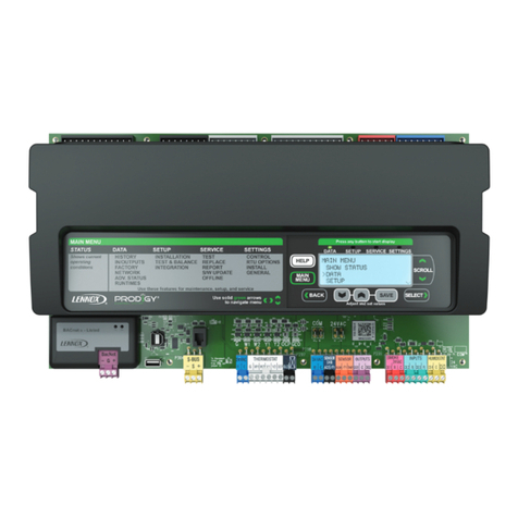
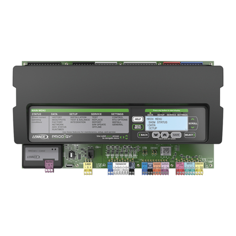
  9. Lennox PRODIGY M2 User manual

Lennox PRODIGY M2 User manual

Other manuals for PRODIGY M2

1

Other Lennox Controllers manuals

Lennox e-Lite LV-CW02 User manual

Lennox

Lennox e-Lite LV-CW02 User manual

Lennox HYDROCONTROL User manual

Lennox

Lennox HYDROCONTROL User manual

Lennox V0STAT52 User manual

Lennox

Lennox V0STAT52 User manual

Lennox @DNOVA pCO1 User manual

Lennox

Lennox @DNOVA pCO1 User manual

Lennox OLT-1X User manual

Lennox

Lennox OLT-1X User manual

Lennox V0STAT54P-2 Installation instructions

Lennox

Lennox V0STAT54P-2 Installation instructions

Lennox HYDRON Series Instruction manual

Lennox

Lennox HYDRON Series Instruction manual

Lennox PRODIGY2.0 User guide

Lennox

Lennox PRODIGY2.0 User guide

Lennox DELTA 2 Owner's manual

Lennox

Lennox DELTA 2 Owner's manual

Lennox PRODIGY M2 User guide

Lennox

Lennox PRODIGY M2 User guide

Lennox VRF F1943L-3P Installation instructions

Lennox

Lennox VRF F1943L-3P Installation instructions

Lennox M0STAT120L-1 User manual

Lennox

Lennox M0STAT120L-1 User manual

Lennox DC 60 User manual

Lennox

Lennox DC 60 User manual

Lennox VRF VEWCL1B User manual

Lennox

Lennox VRF VEWCL1B User manual

Lennox 22U50 User manual

Lennox

Lennox 22U50 User manual

Lennox @DNOVA 2mAC ADVANCED CONTROLLER User manual

Lennox

Lennox @DNOVA 2mAC ADVANCED CONTROLLER User manual

Lennox M0STAT120N-1 User manual

Lennox

Lennox M0STAT120N-1 User manual

Lennox V0STAT54P-2 User manual

Lennox

Lennox V0STAT54P-2 User manual

Lennox CLIMATIC series User manual

Lennox

Lennox CLIMATIC series User manual

Lennox M0STAT64Q-2 Installation instructions

Lennox

Lennox M0STAT64Q-2 Installation instructions

Lennox F1943L-3P User manual

Lennox

Lennox F1943L-3P User manual

Lennox M0STAT64Q-1 Installation instructions

Lennox

Lennox M0STAT64Q-1 Installation instructions

Lennox Core Unit Controller User manual

Lennox

Lennox Core Unit Controller User manual

Lennox E210 Instruction manual

Lennox

Lennox E210 Instruction manual

Popular Controllers manuals by other brands

Sunricher SR-ZV9003T3-RGBW-US Installation

Sunricher

Sunricher SR-ZV9003T3-RGBW-US Installation

Ksenia intro Installation and configuration manual

Ksenia

Ksenia intro Installation and configuration manual

Inovance CAN200 Series manual

Inovance

Inovance CAN200 Series manual

Gauzy LC6 FLEX Controller Installation and operation guide

Gauzy

Gauzy LC6 FLEX Controller Installation and operation guide

Viking SLP-1 Technical practice

Viking

Viking SLP-1 Technical practice

CKD KBX-30E-U Series instruction manual

CKD

CKD KBX-30E-U Series instruction manual

Sharp Energy Sun Flux User manual & installation guide

Sharp Energy

Sharp Energy Sun Flux User manual & installation guide

Yamaha RCX40 user manual

Yamaha

Yamaha RCX40 user manual

AB Quality PowerFlex 400 Frames D-H Service bulletin

AB Quality

AB Quality PowerFlex 400 Frames D-H Service bulletin

Yamaha MJC8 owner's manual

Yamaha

Yamaha MJC8 owner's manual

AL-KO ATC operating instructions

AL-KO

AL-KO ATC operating instructions

Savant SmartControl 2 Deployment guide

Savant

Savant SmartControl 2 Deployment guide

GameSir T3S user manual

GameSir

GameSir T3S user manual

Kostal inveor operating manual

Kostal

Kostal inveor operating manual

Emerson Yarway 20-55 Operating and safety instructions

Emerson

Emerson Yarway 20-55 Operating and safety instructions

CoCo ACM-LV24 Quick installation guide

CoCo

CoCo ACM-LV24 Quick installation guide

Brooks SLA5810/20 Installation and operation manual

Brooks

Brooks SLA5810/20 Installation and operation manual

SIGMA TEK SR 011 Technical manual

SIGMA TEK

SIGMA TEK SR 011 Technical manual

manuals.online logo
manuals.online logoBrands
  • About & Mission
  • Contact us
  • Privacy Policy
  • Terms and Conditions

Copyright 2025 Manuals.Online. All Rights Reserved.

09/09 506215−01
*2P0909* *P506215-01*
Page 1
Litho U.S.A.
E2009
506215−01
09/09 PRODIGYt
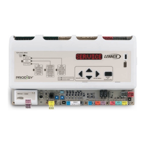
M2 Unit Controller
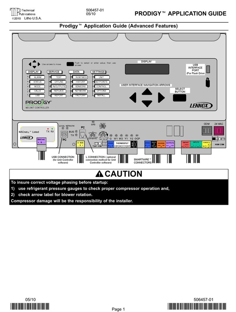
INSTALLATION & SETUP GUIDE FOR THE M2 UNIT CONTROLLER
USED WITH ENERGENCEtROOFTOP UNITS
USB
INTERFACE
PORT
DISPLAY
USER INTERFACE NAVIGATION ARROWS SELECT
BUTTON
ALARM
STATUS
MODE
CALLS
USB
TEST
OFFLINE
IN/OUTPUTS
REPLACE
REPORT
RUNTIMES
HISTORY
SENSORS
NETWORK
FACTORY
UNIT
SETPOINTS
CONTROL
OPTIONS
INSTALL
DISPLAY SERVICE DATA SETTINGS
M2 UNIT CONTROLLER
Push to select or enter value; then use
arrows
Use arrows to move USB
INTERFACE
PORT
(For Flash Drive
DISPLAY
USER INTERFACE NAVIGATION ARROWS
SELECT
BUTTON
L CONNECTION ( optional
connection method for Unit
Controller software)
USB CONNECTION
(for Unit Controller
software)
SMARTWIREt
CONNECTORS
BACnetRtListed
Description
The ProdigytM2 unit controller:
Sprovides control functions for Energencetroof-
top unit,
Sincludes a user interface consisting of a dot ma-
trix display, navigation arrow buttons, a select
button, and a USB port,
Sprovides status & diagnostic information for trou-
bleshooting,
Sallows adjustment of time delays and setpoints
that enable advanced features,
Sis controlled by a standard room thermostat, di-
rect digital controller (DDC), or a zone sensor,
Scan be configured as a device on the network
when daisy−chained to the L Connection®Net-
work,
Smay be connected to a PC which has been
loaded with Unit Controller software,
Saccepts add−on boards to build variations ac-
cording to application or equipment type.
SUSB verification
Table Of Contents
M2 unit controller, expansion board locations,
SmartWiretconnections 2. . . . . . . . . . . . . . . . . . . . . . . .
M2 unit controller LED operation indications 3. . . . . . . . . . . .
Startup 3. . . . . . . . . . . . . . . . . . . . . . . . . . . . . . . . . . . . . . . . . . . .
Menu interface 5. . . . . . . . . . . . . . . . . . . . . . . . . . . . . . . . . . . . .
Operation:
DISPLAY 6. . . . . . . . . . . . . . . . . . . . . . . . . . . . . . . . . . . . . .
SERVICE 7. . . . . . . . . . . . . . . . . . . . . . . . . . . . . . . . . . . . . .
TEST 8. . . . . . . . . . . . . . . . . . . . . . . . . . . . . . . . . . . . .
DATA 9. . . . . . . . . . . . . . . . . . . . . . . . . . . . . . . . . . . . . . . . .
SETTINGS 11. . . . . . . . . . . . . . . . . . . . . . . . . . . . . . . . . . . .
BACnet®15. . . . . . . . . . . . . . . . . . . . . . . . . . . . . . . . . . . . . . . . . .
Networking Controllers 17. . . . . . . . . . . . . . . . . . . . . . . . . . . . . .
Economizer (Damper) 18. . . . . . . . . . . . . . . . . . . . . . . . . . . . . . .
APPENDIX:
Abbreviations 20. . . . . . . . . . . . . . . . . . . . . . . . . . . . . . . . . .
Parts List 20. . . . . . . . . . . . . . . . . . . . . . . . . . . . . . . . . . . . . .
USB Service Report Example 21. . . . . . . . . . . . . . . . . . . .
Alarm Codes 22. . . . . . . . . . . . . . . . . . . . . . . . . . . . . . . . . . .
Wiring Diagrams 25. . . . . . . . . . . . . . . . . . . . . . . . . . . . . . . .
M2 unit controller signal reference diagram 30. . . . . . . . .
M2 unit controller board connections diagram 31. . . . . . .
QUICK START GUIDE (BACK COVER) 32. . . . . . . . . . . .
Page 2
M2 (A55) unit controller − location, controls, inputs/outputs
M2 unit controller board, expansion board locations, SmartWiretconnections
Figure 1 shows the controller components and the locations for expansion boards.
EXPANSION
PORT
ECONOMIZER POTS
AND DIP SWITCHES
(PAGE 18)
EXPANSION
PORT
2 AMP FUSE
CONTROL
BOARD
CONTROL
BOARD
L CONNECTION ( optional
connection method for Unit
Controller software)
USB CONNECTION
(for Unit Controller
software)
Figure 1. M2 unit controller board and expansion boards
Page 3
M2 unit controller LED indicators
Some indicators on the circuit board are visible with the cover in place; others are not. The indicators and their meanings are
described in table 1.
Table 1. LED operation indications
LED Status Indication Meaning
Heartbeat green Slow Flash Normal Operation
green Fast Flash Check 24V, update
firmware, or replace
board
green Steady Off No voltage to M2 board
or defective board
green Steady On Defective Board (re-
place)
OAS
green Steady ON Outside air is suitable
green Flashing
IAQ mode or mechani-
cal cooling during free
cooling
PC
Connection
Local
(amber) Flickering ON Communication to PC
USB connector
Network
(green) Flickering ON Network communica-
tion
LED Status Indication Meaning
S−BUS BUS
(green) Flickering ON Network traffic present
TX
(amber) Flickering ON M2 is transmitting
BACnet RX (green) Flickering ON M2 is receiving
TX (red) Flickering ON M2 is transmitting
Thermostat
Input
amber Indicates a
thermostat de-
mand
G− Blower on
W1− 1st stage heat
W2− 2nd stage heat
Y1− 1st stage cool
Y2− 2nd stage cool
OCP−Occupied
Thermostat LEDs indicate only with incoming thermostat connection
vis SmartWire connector.
Slow Flash = 1 sec on; 1 sec off.
Fast Flash = 1 msec on; 1 msec off.
A flickering" LED flashes significantly faster than a fast flash.
NOTE − LEDs are energized by 24 vac thermostat inputs.
Startup
Connections between RTU & M2 unit controller
The M2 unit controller connects to the rooftop unit using
SmartWiretconnectors. Each connector is keyed" so
that no connector can be installed in the wrong location. Be
sure all connectors are in place and completely inserted
(see figure 1).
Sensor Common Isolation
Thermostat (TSTAT) and humidity (HUM) sensor com-
mons may be isolated if they are powered remotely. Slide
switch to OPEN to isolate (see figure 1).
USB interface usage
The USB port is used for service verification and for down-
loading reports. Onsite data collection requires use of a
USB flash drive. Data written to the drive includes date,
time, serial number, catalog number, basic data, and error
code buffer. Technicians then transfer the data to a PC and
then forward encrypted files to billing personnel for service
history verification.
PC interface
The PC interface is used with unit controller software to
change programming. The M2 interface uses a USB A to B
male cable. You may also continue to use 9 pin/RS485
connection to the phone jack or S−BUS connector as be-
fore. A list of service connection kits is on Page 20.
SmartWire Field Wiring Connections
The SmartWire connectors, P297, P298 and P299, al-
low for easy field wiring connection points.
2−amp fuseThe 24VAC supply outputs, (R), on these
connectors are routed through the fuse, F1. This fuse is a
standard 2−amp, automotive−style blade fuse. This fuse
protects the Prodigy controller from field wiring mis−wires.
TSTAT COMThe switch "TSTAT COM" is located to the
left of P297. This switch is used only in unique situations
where the device supplying the thermostat signals to the
Prodigytcontroller has its own power source and does
not share a common reference voltage with the Prodigyt
controller. Otherwise the TSTAT COM switch needs to be
set to the default, closed position, to the right.
HMD COMThe switch "HMD COM" is located to the right
of P299. This switch is used only in unique situations
where the device supplying the dehumidify command sig-
nal to the Prodigytcontroller has its own power source
and does not share a common reference voltage with the
Prodigytcontroller. Otherwise the HMD COM switch
needs to be set default, closed position, to the left.
Page 4
Startup (continued)
User interface menu
The user interface is accessed through the menu naviga-
tion arrows and the select button . The diagram
in figure 2 shows a high level overview of the main menu
options along with the next level list of selections. The low-
er level options are described later in this manual.
Home" location, DISPLAYWhen the unit is powered
on, one of the features in the DISPLAY column will be
shown (the word ’DISPLAY’ is never shown). What is dis-
played in this home" screen, is dependant on the priority
message present at the time, in priority order of top−to−bot-
tom of the left column in figure 2. For example, if an alarm is
present, that will be displayed until it has been silenced or
cleared.
To access the other three columns, first press and then
use to scroll between SERVICE, DATA, AND SET-
TINGS. Next, press to open the SERVICE (or DATA or
SETTINGS) menu. Use until desired item is dis-
played.
To return to DISPLAY, use (hold it down if you are deep in
the menu structure and you will be stepped back to DIS-
PLAY.
ALARM
STATUS
MODE
CALLS
USB
TEST
OFFLINE
IN / OUTPUTS
REPLACE
REPORT
RUNTIMES
HISTORY
SENSORS
NETWORK
FACTORY
UNIT
SETPOINTS
CONTROL
OPTIONS
INSTALL
DISPLAY
Dashed line for automatic
displayed messages
SERVICE DATA SETTINGS
Use arrows to move
Use arrows to move
Use arrows to move
NOTE − Use the left button during normal
operation to clear delays (hold 2 seconds)
or reset the controller (5 seconds).
Figure 2. M2 unit controller main interface menu
Page 5
Menu Interface
Table 2 shows the major levels of the menu interface.
Many of these options have more levels and are described
in the following sections that detail DISPLAY, SERVICE,
DATA, and SETTINGS.
Use rectangular button to progress to next
lower level (i.e. Level 1 to Level 2).
Use left arrow toback up" to the next higher level
(i.e. Level 2 to Level 1).
Use the up/down arrows to move within a level
and change values of selected item.
Table 2. Menu Interface
Level 1 Level 2 Level 3
NOTE − Features and options not currently available are greyed out in
the manual and will show a message of N/A" on the display
(display
area)
ALARM SILENCE (push any button to silence)
STATUS SILENCE (push any button to silence)
MODE
BLOWER
COOLING
FREE COOLING
FRESH AIR COOL
FRESH AIR HEAT
HEATING
HVAC OFF
IDLE
MORNING
WARMUP
M2 FAILED TO
RESPOND
PRE−COOL
PRE INSTALL
REHEAT
SMOKE
TEST
CALLS
TSTAT Y1, etc
BACNET Y1, etc
LONTALK Y1, etc
LCONN Y1, etc
BUILDING Y1, etc
USB
WRITING USB
WRITING ALARM/STATUS LOG
USB COMPLETE
SER-
VICE
USE ARROWS TO MOVE
TEST
GUIDED
BLOWER
FANS
COOL
HEAT
DAMPER
REHEAT
SENSORS
OUTPUTS
CONTROLLER
OFFLINE
LOCKOUT
BLOWER ONLY
COOLING ONLY
HEATING ONLY
RESET
IN /
OUTPUTS
ZONING
SENSORS
RELAYS
NETWORK
OUTPUTS
REPLACE
FILTER
BELT
UV LAMP
FANS
BLOWER
COMPRESSOR
REPORT MAKE REPORT
READ INSTALL
READ FACTORY
Table 2. Menu Interface (cont’d)
Level 1 Level 2 Level 3
DATA
USE ARROWS TO MOVEUSE ARROWS TO MOVEUSE ARROWS TO MOVEUSE ARROWS TO MOVE
RUNTIMES
POWER ON
FILTER: XX HRS
BELT: XX HRS
UV LAMP: XX HRS
BLOWER: XX HRS − XX CYC
COOLING
HEATING
FREE COOLING: XX HRS − XX
CYC
FANS
EXHAUST
REHEAT: XX HRS − XX CYC
HISTORY
ALARMS
STATUS
LAST USB
READ INSTALL RPT
CLEAR HISTORY
SENSORS
(also
accessible
thru In /
Outputs)
TSTAT
BRPM:XX
DPOS:XX%
OAT:XXºF
RAT:XXºF
DAT:XXºF
ZAT:XXºF
IAQ:XX PPM
SMK:OFF/ON
RH:XX%
IE:XX MA
OE:XX MA
GLO:OFF/ON
DI2:OFF/ON
DI3:OFF/ON
DI4:OFF/ON
NETWORK
LCONN ADDRESS
BACNET ADDRESS
LONTALK ADDRESS
FACTORY
READ M2 SOFTWARE
VERSION
READ DB SOFTWARE
VERSION
READ FACTORY RPT
CATALOG NO.
MODEL NO.
SERIAL NO.
SET-
TINGS
USE ARROWS TO MOVE
UNIT
UNIT NO.
DATE/TIME
UNITS F/C
SETPOINTS
COOLING
HEATING
DAMPER
REHEAT
EXHAUST
IAQ
CONTROL
GUIDED SETUP
LOCAL
THERMOSTAT
LCONN
BACNET
LONTALK
MSAV
REHEAT
OPTIONS RESERVED
INSTALL
NEW M2
DAMPER
FLOAT SW
BLOWER PROVING SW
PHASE MONITOR
UV LAMP
ELECTRIC HEAT STAGES
UPDATE DISPLAY SOFTWARE
Page 6
Menu Interface DISPLAY
The display shows operating mode if in normal operation.
Alarm, status, calls and plugging in the USB will interrupt
the display. Alarm messages will stay displayed until cor-
rected or silenced using the local menu.
DISPLAY
ALARM
STATUS
MODE
CALLS
USB
Dashed line for automatic
displayed messages
ALARM Example ˘ MODE message
COOLING" is displaying when a smoke
alarm occurs; then ALARM:(XX) SMOKE
A17" displays until cleared. You must
clear all alarms and status to see normal
MODE message. Strike 3 alarms will say
ALARM(XX):STRIKE 3 COMP1 HIGH
PRESS S4" after the alarm message.
USB ˘ normal MODE message is dis-
played when USB is plugged in; message
examples:
WRITING USB"
WRITING ALARM/STATUS LOG"
USB COMPLETE"
Normal Mode Messages
The format of the message is mode and setpoint (see table
3).
Table 3. Possible MODE messages
BLOWER Blower only
COOLING Cool demand present; unit is cooling
FREE COOLING No compressor cooling
FRESH AIR COOL Cool ventilation air to neutral value
FRESH AIR HEAT Heat ventilation air to neutral value
HEATING Heat demand present; unit is heating
HVAC OFF No heat, cool, ventilation allowed
IDLE Demand satisfied; blower off
MORNING WARMUP Outdoor air damper closed
M2 FAILED TO RESPOND Display is missing messages from
M2
PRE−COOL No compressor allowed when free
cooling
PRE−INSTALL Must follow installation menus
REHEAT Unit is dehumidifying
SMOKE Smoke input detected
TEST Network has unit in test mode
(blank screen) Bootloader mode
Unit Operation
This section describes the display and control buttons,
how to configure the unit, and how to read stored configu-
ration data, status, and alarms.
The M2 unit controller is an input and output junction
point. If in the thermostat mode, thermostat inputs at
P297 result in an output to unit components (see table 11
on Page 30). If the heartbeat LED is not flashing, see
table 1 (Page 3) for heartbeat operation. If the display
shows an alarm, refer to table 10 (Page 22) for more in-
formation. If the thermostat input indicating lights are not
responding appropriately, check the thermostat or a
DDC control acting as thermostat inputs into P297.
Basic cooling and heating functions may be energized to
test major unit components by using the M2 unit controller
testing function or by using jumper wires on the Field Wir-
ing Termination plug P297.
To access the other three columns, first press and then
use to scroll between SERVICE, DATA, AND SET-
TINGS. Next, press to open the SERVICE (or DATA or
SETTINGS) menu. Use until desired item is dis-
played.
Alarms
Figure 3 shows a typical alarm and how the message will
scroll.
ALARM(xx): SMOKE DETECTED.
DISPLAY
WINDOW
LEFT SCROLLING
MESSAGE
(To SILENCE an alarm,
press any of these buttons.)
Figure 3. Alarm Code Readout Example
SILENCE − to silence an alarm, press any of the control
buttons while the alarm is displayed.
USB Service Verification
When the Lennox USB drive is plugged in during normal
MODE, a message will be displayed to indicate data is be-
ing written to the drive. When finished, the message USB
COMPLETE" will be displayed.
From the USB you may get the last report from the M2 unit
controller and view it using any PC text program.
Multiple units may use the same USB drive. The filename
of the service reports will be based on the unit’s serial num-
ber; for example 5608J5875.txt.
Page 7
Menu Interface SERVICE
From the DISPLAY mode, press and then use to
scroll to SERVICE. Next, press to enter the SERVICE
menu. Use until desired item is displayed.
SERVICE
TEST
OFFLINE
IN / OUTPUTS
REPLACE
REPORT
Use arrows to move
Using SERVICE, you may run tests that
check a functional operation (e.g. HEAT-
ING) or you may run tests that single out
a system component for checking. The
diagram below shows how to navigate
through the system to access a functional
test or a component test.
When the list of tests appears, use the
up/down arrows until the test you want to
run appears. Then press the SELECT
BUTTON to begin running the test.
SERVICE > TEST
In the SERVICE menu, use until TEST is displayed.
Press to enter the TEST menu.
Use arrows to move
GUIDED
BLOWER
FANS
COOL
HEAT
DAMPER
REHEAT
SENSORS
OUTPUTS
CONTROLLER
TEST
TEST is described in
detail in table 4
[Page 8]).
Using the TEST menu, the service technician may run a
sequence of tests to gather information available while that
component is turned on. The unit will return to normal
mode when leaving the TEST menu. See table 4 for de-
tails.
Any Status/Alarm codes found during testing will be logged
to the event history.
Upon exit from TEST mode, the unit will return to normal
operation if no key is pushed for 1 hour.
SERVICE > OFFLINE
In the SERVICE menu, use until OFFLINE is dis-
played. Press to enter the OFFLINE menu.
Use arrows to move
LOCKOUT
BLOWER ONLY
COOLING ONLY
HEATING ONLY
RESET
OFFLINE
SERVICE > IN / OUTPUTS
In the SERVICE menu, use until IN / OUTPUTS is dis-
played. Press to enter the IN / OUTPUTS menu.
Use arrows to move
ZONING
SENSORS
RELAYS
NETWORK
OUTPUTS
IN/OUTPUTS
SERVICE > REPLACE
In the SERVICE menu, use REPLACE to reset the runtime
counters for the listed device when a new hardware com-
ponent has been installed in the system.
Use until REPLACE is displayed. Press to enter
the REPLACE menu. This will reset the runtime for the new
part to zero.
Use arrows to move
FILTER
BELT
UV LAMP
FANS
BLOWER
COMPRESSOR
REPLACE
Page 8
Menu Interface SERVICE (Continued)
SERVICE > TEST (Continued)
Table 4. TEST
Use arrows to move
GUIDED
BLOWER HIGH K3 HK3 OFF/ON Run blower on maximum speed
LOW K3 LK3 OFF/ON Run blower on minimum speed
PROVING SWITCH Display status of the switch with blower low speed.
FILTER SWITCH Display status of the switch with blower low speed
RPM XX RPM Shows RPM for blower and allows adjustment
FANS FAN1 FN1 OFF/ON Allow turning on fan1 individually
FAN2 FN2 OFF/ON Allow turning on fan2 individually
COOL COOL 1 (compr low) RAT Monitors return air temperature. Stage 1 compr low−speed test. Dampers are closed for
compressor tests.
DAT Monitors discharge air temperature. Blower, dampers, fans are actuated automatically
during tests.
COOL 2 (compr hi) RAT Monitors return air temperature. Stage 2 compr low−speed test. Dampers are closed for
compressor tests.
DAT Monitors discharge air temperature. Blower, dampers, fans are actuated automatically
during tests.
HEAT HEAT 1 RAT Monitors return air temperature. Stage 1 heat test; dampers automatically close and blower
comes on for heat test.
DAT Monitors discharge air temperature. Stage 1 heat test; dampers automatically close and
blower comes on for heat test.
HEAT 2 RAT Monitors discharge air temperature. Stage 2 heat test; dampers automatically close and
blower comes on for heat test.
DAT Monitors discharge air temperature. Stage 2 heat test; dampers automatically close and
blower comes on for heat test.
DAMPER POSITION OPEN: XX % Damper allows testing economizer, motorized damper, and powered exhaust. Position
allows monitoring damper position and control using arrow keys.
IEN: XX MA Monitors indoor enthalpy sensor.
OEN: XX MA Monitors outdoor enthalpy sensor.
EXHAUST EXHAUST 1 EXH1:OFF/ON Turns on stage 1 fan individually.
EXHAUST 2 EXH2:OFF/ON Turns on stage 2 fan individually.
REHEAT HUM − Y1 HUM − Y1 OK Turns on stage 1 reheat; displays report.
HUM &−Y2 HUM − Y2 OK Turns on stage 2 reheat; displays report.
SENSORS
OUTPUTS SERVICE RELAY RELAY OFF/ON Output test of service relay.
DO2 DO2 OFF/ON Output test of DO2.
DO3 DO3 OFF/ON Output test of DO3.
CONTROLLER M2 TEST M2 OK" if no errors. Checks memory and
installation of controller options.
DISPLAY TEST TEST OK" if no errors. Checks switches and screen.
SETUP SETUP OK" if no errors. Checks proper installation of controller boards,
switches, and settings
TEST
Use ar-
rows to
move
Use ar-
rows to
move
Use ar-
rows to
move
Use ar-
rows to
move
Use ar-
rows to
move
TSTAT
BRPM:XX
DPOS:XX%
OAT:XX ºF
RAT:XX ºF
DAT:XX ºF
ZAT:XX ºF
IAQ:XX PPM
SMK:OFF/ON
RH:XX%
IE:XX MA
OE:XX MA
GLO:OFF/ON
D12:OFF/ON
DI3:OFF/ON
DI4:OFF/ON
Use sensor tests to choose each sensor
and read the current sensed value.
Page 9
Menu Interface DATA
From the DISPLAY mode, press and then use to
scroll to DATA. Next, press to enter the DATA menu.
Use until desired item is displayed.
Use DATA to view information stored in the M2 Unit Con-
troller.
DATA
RUN TIMES
HISTORY
SENSORS
NETWORK
FACTORY
Use arrows to move
DATA > RUNTIMES
In the DATA menu, use until RUNTIMES is displayed.
Press to enter the RUNTIMES menu.
View accumulated runtime hours logged against various
components and systems by the M2 unit controller.
Use arrows to move
POWER ON
FILTER: XX HRS
BELT: XX HRS
UV LAMP: XX HRS
BLOWER: XX HRS
COOLING
HEATING
FREE COOLING: XX HRS − XX CYC
FANS
EXHAUST
REHEAT: XX HRS − XX CYC
RUNTIMES
As each entry is listed, its ac-
cumulated runtime is automati-
cally displayed.
DATA > HISTORY
In the DATA menu, use until HISTORY is displayed.
Press to enter the HISTORY menu.
Read the accumulated historical data of alarms, status,
and USB reports logged by the M2 unit controller.
Use arrows to move
ALARMS
STATUS
LAST USB REPORT
READ INSTALL
CLEAR HISTORY
HISTORY
Use the up/down arrows
to scroll through a list of
ALARMS and STATUS
events
DATA > SENSORS
In the DATA menu, use until SENSORS is displayed.
Press to enter the SENSORS menu.
View the current sensed value for various systems being
sent to the M2 unit controller.
TSTAT
BRPM:XX
DPOS:XX%
OAT:XXºF
RAT:XXºF
DAT:XXºF
ZAT:XXºF
IAQ: XX PPM
SMK: OFF/ON
RH: XX%
IE: XX MA
OE: XX MA
GLO: OFF/ON
DI2: OFF/ON
DI3 OFF/ON
DI4: OFF/ON
Use arrows to move
SENSORS
As each sensor is listed, its
reading is automatically dis-
played.
Page 10
Menu Interface DATA (Continued)
DATA > NETWORK
In the DATA menu, use until NETWORK is displayed.
Press to enter the NETWORK menu.
Read the NETWORK addresses stored in the M2 unit con-
troller.
Use arrows to move
LCONN ADDRESS
BACNET ADDRESS
LONTALK ADDRESS
NETWORK
Use the up/down arrows
to scroll through a list of
device addresses
DATA > FACTORY
In the DATA menu, use until FACTORY is displayed.
Press to enter the NETWORK menu.
Read the FACTORY information stored in the M2 unit con-
troller. Use
Use arrows to move
READ M2 SOFTWARE VERSION M2 VX.XX
READ DB SOFTWARE VERSION DB1 VX.XX
READ FACTORY REPORT
CATALOG NO. (catalog number)
MODEL NO. (model number)
SERIAL NO. (serial number)
FACTORY
Use the up/down arrows
to scroll through the read-
able entries. Use the se-
lect button to view soft-
ware versions.