Safety instructions
General safety information
2
9
Lenze ¯ BA_p500 ¯ 3.0
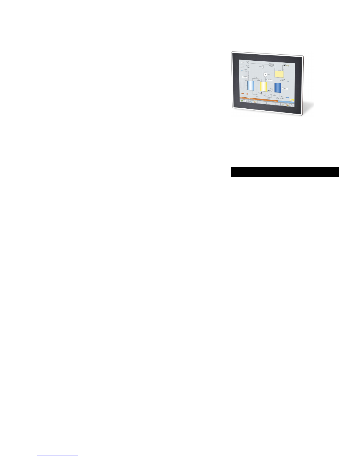
Mechanical installation
¯ Install the product according to the regulations of the corresponding
documentation. In particular observe the section "Operating conditions" in the
chapter "Technical data".
¯ Provide for a careful handling and avoid mechanical overload. During handling
neither bend components, nor change the insulation distances.
¯ The product contains electrostatic sensitive devices which can easily be damaged
by short circuit or static discharge (ESD). Thus, electronic components and
contacts must not be touched unless ESD measures are taken beforehand.
Electrical installation
¯ Carry out the electrical installation according to the relevant regulations (e. g.
cable cross−sections, fusing, connection to the PE conductor). Additional notes are
included in the documentation.
¯ When working on live products, observe the applicable national regulations for
the prevention of accidents (e.g. BGV 3).
¯ The Instructions contain notes concerning wiring according to EMC regulations
(shielding, earthing, filters and cable routing). The compliance with limit values
required by the EMC legislation is the responsibility of the manufacturer of the
machine or system.
Warning: The inverters are automation components which can be used in industrial
environment according to EN 61000−6−4. These products may cause radio
interference in residential areas. If this happens, the operator may need to take
appropriate action.
¯ For compliance with the limit values for radio interference emission at the site of
installation, the components − if specified in the technical data − have to be
mounted in housings (e. g. control cabinets). The housings have to enable an
EMC−compliant installation. In particular observe that for example control cabinet
doors preferably have a circumferential metallic connection to the housing.
Reduce openings or cutouts through the housing to a minimum.
¯ Only plug in or remove pluggable terminals in the deenergised state!
Commissioning
¯ If required, you have to equip the system with additional monitoring and
protective devices in accordance with the respective valid safety regulations (e. g.
law on technical equipment, regulations for the prevention of accidents).
Maintenance and servicing
¯ The components are maintenance−free if the required operating conditions are
observed.
¯ If the cooling air is polluted, the cooling surfaces may be contaminated or the air
vents may be blocked. Under these operating conditions, the cooling surfaces and
air vents must be cleaned at regular intervals. Never use sharp objects for this
purpose!
¯ After the system has been disconnected from the supply voltage, live components
and power connections must not be touched immediately because capacitors may
be charged. Please observe the corresponding notes on the device.