Lenze P500 series User manual

P50GAP.../P50GAH...
Panel Controller/HMI
Ä.U)kä
.U)k
Montageanleitung DE
EN
FR
ES
IT
Mounting Instructions
Instructions de montage
Instrucciones para el montaje
Istruzioni per il montaggio
p500

2
KFZ_Zeichen_DE−M−Install_WiHis_Panel_Controller
Lenze ¯ MA_p500 ¯ 8.0
Lesen Sie zuerst diese Anleitung und das Controller−Referenzhandbuch, bevor
Sie mit den Arbeiten beginnen.
Beachten Sie die enthaltenen Sicherheitshinweise!
Tipp!
Informationen und Hilfsmittel rund um die Lenze−Produkte finden Sie im
Download−Bereich unter
www.lenze.com
Diese Anleitung ist gültig für:
ƒ Panel Controller p500 (P50GAP...)
ƒ HMI p500 (P50GAH...)
Bestimmungsgemäße Verwendung
Der Panel Controller/HMI ist ein elektrisches Betriebsmittel ...
ƒ zum Einbau (horizontal oder vertikal) in Schaltschränke oder ähnliche
abgeschlossene Betriebsräume;
ƒ zur Umsetzung von Steuerungs− und Bedienkonzepten oder zur Darstellung von
Informationen in gewöhnlichen industriellen und gewerblichen Bereichen.
Das Gerät kann in vertikaler Standard−Einbaulage bei einer Umgebungslufttemperatur
bis max. 55 °C betrieben werden.
Eine andere oder darüber hinaus gehende Verwendung ist nicht zulässig!
Für die Gewährleistung des Personen− und Sachschutzes müssen übergeordnete Sicher-
heitssysteme eingesetzt werden!
Open Source Hinweis
Lenze Software kann Software−Bestandteile enthalten, die als Freie Software oder als Open
Source lizensiert sind. Die Lizenzbedingungen der in diesem Produkt verwendeten Open
Source Software−Komponenten stehen Ihnen auf der im Produkt enthaltenen SD−Karte im
Verzeichnis "Licenses" zur Verfügung.

3
KFZ_Zeichen_DE−M−Install_WiHis_Panel_Controller
Lenze ¯ MA_p500 ¯ 8.0
Wichtige Hinweise
ƒ Montage/Demontage bei ausgeschalteter Versorgungsspannung durchführen, um
elektronische Bauteile vor Beschädigung zu schützen.
ƒ Im Einbauraum ist eine ständige und ausreichende Luftzirkulation zwingend
erforderlich, um die Wärme des Geräts abzuleiten. Die Lüftungsschlitze dürfen nicht
abgedeckt werden.
ƒ Achten Sie bei der Wahl des Aufstellortes auf eine ergonomische Stellung des
Bildschirms, sowie auf Lichteinfall, der Reflektionen auf dem Bildschirm verursachen
könnte. Das Gerät vor direkter Sonneneinstrahlung schützen, da sich das Gehäuse
stark aufheizen kann.
ƒ Während der Montage besteht die Gefahr, dass das Gerät aus dem Einbauausschnitt
fällt. Sichern Sie es deshalb gegen Herunterfallen, bis es montiert ist.
ƒ Während der Montage liegt der Dichtring des Frontrahmens frei und kann
beschädigt werden.
– Kontrollieren Sie den Dichtring vor der Montage auf Unversehrtheit.
– Gehen Sie während der Montage sorgsam mit dem Dichtring um.
– Schützen Sie den Dichtring vor UV−Strahlen.
ƒ Das Gerät muss fest im Einbauausschnitt sitzen und die Frontplattendichtung muss
korrekt aufliegen. Andernfalls wird auf der Gerätevorderseite die Schutzklasse IP65
nicht erreicht! (IP−Rating ist nicht UL−approbiert.)
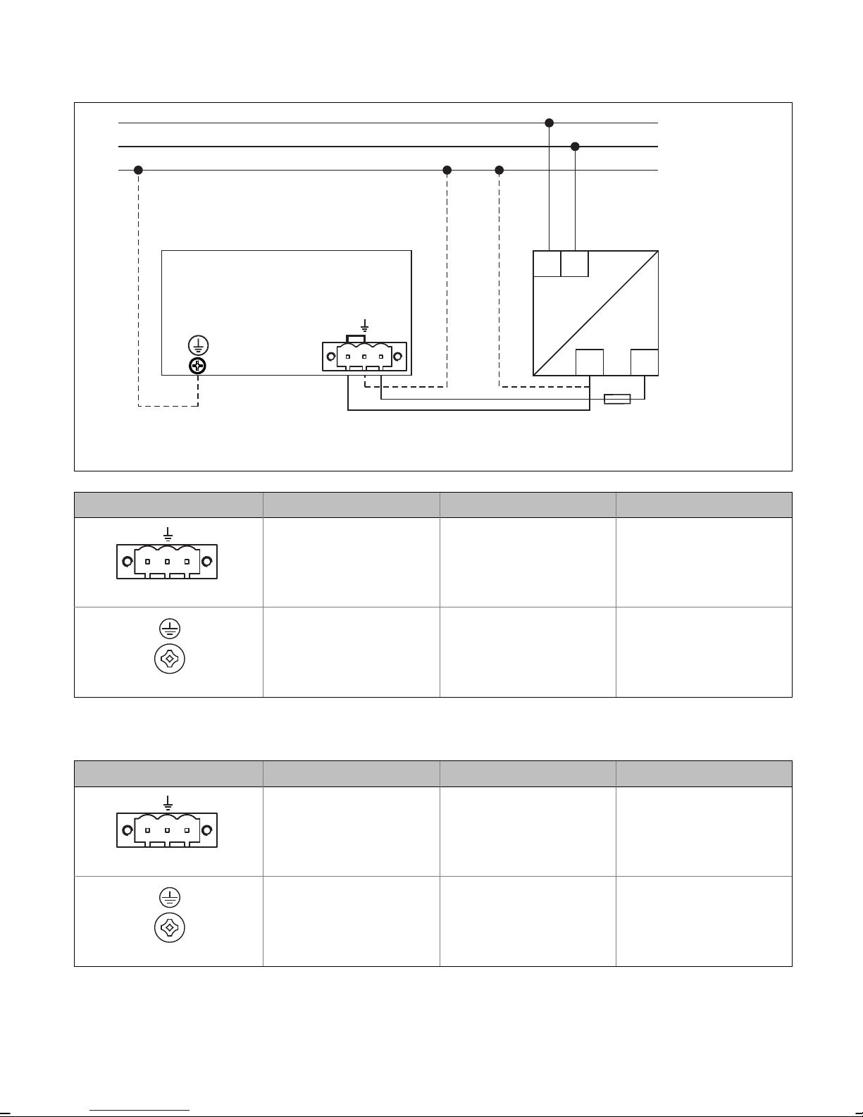
ƒ Das Gerät muss mit einer PELV−Versorgung betrieben werden.
ƒ Der Spannungseingang ist intern nicht abgesichert. Bei zu hohen
Eingangspannungen kann das Gerät zerstört werden. Beachten Sie die maximal
zulässige Eingangsspannung und sichern Sie das Gerät eingangsseitig fachgerecht
gegen Spannungsschwankungen und −spitzen ab.

4
KFZ_Zeichen_EN−M−Install_WiHis_Panel_Controller
Lenze ¯ MA_p500 ¯ 8.0
Please read these instructions and the controller reference manual before you
start working.
Observe the provided safety instructions!
Tipp!
Information and tools concerning the Lenze products can be found in the
download area at
www.lenze.com
These instructions are valid for:
ƒ Panel Controller p500 (P50GAP...)
ƒ HMI p500 (P50GAH...)
Application as directed
The Panel Controller/HMI is electrical equipment ...
ƒ for the installation (horizontal or vertical) in control cabinets or similar closed
electrical operating areas;
ƒ for the implementation of control concepts and operational concepts or for the
representation of information in ordinary industrial and commercial areas.
The Controller can be operated in a vertical standard mounting position at a surrounding
air temperature of max. 55 °C.
A different use, or one beyond these purposes, is not permissible!
In order to ensure the protection of persons and material assets, higher−level safety systems
must be used!
Open source notice
Lenze Software may contain software elements that are licensed as free software or open
source. The licensing terms and conditions of the open source software components used
in this product can be found in the "License" directory on the SD card included in the pro-
duct.

5
KFZ_Zeichen_EN−M−Install_WiHis_Panel_Controller
Lenze ¯ MA_p500 ¯ 8.0
Important notes
ƒ To prevent damage to electronic components, only mount/remove the device with
the voltage supply switched off.
ƒ In the installation space, continuous and sufficient air circulation is absolutely
required to dissipate the heat of the device. The ventilation slots must not be
covered.
ƒ When selecting the installation space, be sure to observe an ergonomic position of
the screen and pay regard to the incidence of light, which may cause reflections on
the screen. Protect the device from direct solar radiation, as the housing may heat up
considerably.
ƒ During mounting, there is a danger that the device will fall out of the mounting
cutout. You should therefore secure it to prevent this happening until it have been
fitted.
ƒ During mounting, the gasket of the front frame is exposed and can be damaged.
– Before mounting, make sure that the gasket is undamaged.
– Handle the gasket with care during mounting.
– Protect the gasket against ultraviolet rays.
ƒ The device must be securely seated in the mounting cutout and the front panel seal
must be correctly fitted. Otherwise, class of protection IP65 will not be achieved on
the front side of the device! (IP rating is not UL−approved.)
ƒ The device has to be powered with a PELV supply.
ƒ The voltage input is not fused internally. The device can be destroyed when the input
voltage is too high. Observe the max. permissible input voltage and professionally
fuse the device on the input side against voltage fluctuations and voltage peaks.

6
M5_Anschl_Schnittstelle−Stromaufnahe_p500_Tab
Lenze ¯ MA_p500 ¯ 8.0
Anschlüsse und Schnittstellen
Connections and interfaces
ABCDE F I J
K
L
G H
p500_010
Pos. Beschreibung
ALAN 1a; 10/100 MBit/s mit integrietem Switch
BUSB 2.0; z. B. für Tastatur
CLAN 1b; 10/100 MBit/s mit integrietem Switch
DUSB 2.0; z. B. für USB−Stick (Backup)
E EtherCAT
FSD−Karte; Datenspeicher für Projektdaten
GStatusanzeigen (4 LEDs); s. Controller Referenzhandbuch oder »PLC Designer« Hilfe
H Reset−Taster
ISpannungsversorgung (24 V DC)
J Reserviert
KOptionale Schnittstelle für MC−Cards (Erweiterung um Bussysteme)
L PE−Anschlussschraube
Pos. Description
ALAN 1a; 10/100 Mbps with an integrated switch
BUSB 2.0; e. g. for connecting a keyboard
CLAN 1b; 10/100 Mbps with an integrated switch
DUSB 2.0; e. g. for connecting a USB stick (data backup)
E EtherCAT
FSD card; Data memory for project data
GStatus notifications (4 LEDs); see controller reference manual or »PLC Designer« help
HReset button
IVoltage supply (24 V DC)
J Reserved
KOptional interface for MC cards (extension by bus systems)
LPE terminal screw

7
M5_Anschl_Schnittstelle−Stromaufnahe_p500_Tab
Lenze ¯ MA_p500 ¯ 8.0
Abmessungen
Dimensions
a2
a1
a
e1
e3
b2
b1
b
e2
> 40 mm
(1.57")
!
> 40 mm
(1.57")
> 40 mm
(1.57")
> 40 mm
(1.57")
> 40 mm
(1.57")
p500_004
p500 mm (inch)
a a1 a2 b b1 b2 e1 e2 e3
17.8 cm (7.0") 210
(8.27")
191
(7.52")
182
(7.17")
155
(6.10")
136
(5.35")
104
(4.09")
82
(3.23")
4
(0.16")
22
(0.87")
26.4 cm (10.4") 282
(11.10")
263
(11.10")
240
(9.45")
221
(8.70")
38.1 cm (15.0") 390
(15.35")
371
(14.61")
310
(12.20")
291
(11.46")
87
(3.43")
6
(0.24")
27
(1.06")

8
M5_Anschl_Schnittstelle−Stromaufnahe_p500_Tab
Lenze ¯ MA_p500 ¯ 8.0
Montageschritte
Installation steps
1.
!
m
n
£5 mm
p500_006
p500 mm (inch)
m n [kg]
17.8 cm (7.0") 194 (7.64") 139 (5.47") 1.4
26.4 cm (10.4") 266 (10.47") 224 (8.82") 2.5
38.1 cm (15.0") 374 (14.72") 294 (11.57") 4.5
2.
a
b
c
x
17.8 cm (7.0") = 4 x
26.4 cm (10.4") = 8 x
38.1 cm (15".0) = 10 x
max. 20 Ncm
max. 1.7 lbin
3.
17.8 cm (7.0") = 4 x
26.4 cm (10.4") = 8 x
38.1 cm (15".0) = 10 x
p500_007 p500_008
x Schraubspanner−Positionierhilfe
x Positioning aid for screw clamps

9
M5_Anschl_Schnittstelle−Stromaufnahe_p500_Tab
Lenze ¯ MA_p500 ¯ 8.0
Spannungsversorgung (24 V) anschließen
Connecting voltage supply (24 V)
L1
N
PE
L1 N
0V
+24
~=
F
(max. 20 A)
PE
PELV
10 lb-in
(1.1 Nm)
ControllerController
0V U
cp300−006
Abbildung Anschluss Anschlusstyp Kabeltyp
0V U
Netzanschluss
(24 V DC) 3−pol. Combicon−
Buchse
Kabel mit
Combicon−Stecker
(Leiterquerschnitt max.
2.5 mm2, AWG14)
IPC001
PE−Anschluss Schraube: M4 (PH 2)
Sep. Erdungsleiter mit
Ringkabelschuh
(Leiterquerschnitt min.
2.5 mm2, AWG14)
IPC001
Wird der PE−Leiter nicht mit der Versorgung zugeführt, muss das PE−Potential an einem Er-
dungspunkt in der Nähe des Einbauortes aufgelegt werden.
Figure Connection Connection type Cable type
0V U
Mains connection
(24 V DC) 3−pin Combicon socket
Cable with Combicon
plug (max. conductor
cross−section 2.5 mm2,
AWG14)
IPC001
PE connection Screw: M4 (PH 2)
Separate earth conduc-
tor with ring cable lug
(min. conductor cross−
section 2.5 mm2,
AWG14)
IPC001
If the PE conductor is not included in the supply cable, the PE potential must be applied at
an earthing point near the mounting place.

10
M5_Anschl_Schnittstelle−Stromaufnahe_p500_Tab
Lenze ¯ MA_p500 ¯ 8.0
Stromaufnahme
Current consumption
p500
Imax [A]
17.8 cm (7") 26.4 cm (10.4") 38.1 cm (15")
Ohne Optionskarten und USB−Verbraucher 0.5 0.6 0.7
2 x 500 mA USB 1+2, inkl. MC−CAN2,
max. 30 s nach dem Einschalten 1.2 1.3 1.5
p500
Imax [A]
17.8 cm (7") 26.4 cm (10.4") 38.1 cm (15")
Without option cards and USB consumer 0.5 0.6 0.7
2 x 500 mA USB 1+2, incl. MC−CAN2,
max. 30 s after switch−on 1.2 1.3 1.5

11
UL_Warn_p500
Lenze ¯ MA_p500 ¯ 8.0
Approval accoding to UL
Underwriter Laboratories (UL), UL508 and CSA C22.2 No. 142−M1987, (UL File Number
E236341)
Ratings
ƒ Input 24 V DC, max. 1.7 A
ƒ Max. surrounding air temperature:
– p500 7.0": 55 °C, in vertical (landscape or portrait) mounting position only at
relative humidity of 60 % rh with a linear derating to 30 °C at 90 % rh.
– p500 10.4": 55 °C in vertical (landscape or portrait) mounting position only at a
relative humidity of 55 % rh with a linear derating to 40 °C at 90 % rh.
– p500 15.0": 55 °C in vertical (landscape or portrait) mounting position only at a
relative humidity of 45 % rh with a linear derating to 40 °C at 90 % rh.
Warnings!
Field Wiring Markings
Wiring terminal: Voltage supply (24 V DC)
ƒUse 60 °C or 60/75 °C copper wire only.
ƒAWG 18 ... 12 (0.82 ... 3.3 mm2)
ƒTorque 5 ... 7 lb−in (0.5 ... 0.6 Nm)
Device
ƒFor use in a pollution degree 2 and controlled environment only.
ƒThese devices are intended for mounting on a flat surface of an enclosure
type 1, 4 and 4X (indoor use only).
ƒUse this product only in the manner described in this manual. If the
equipment is used in a manner not specified by the manufacturer, the
protection provided by the equipment may be impaired.
Fieldbus interfaces / Optional filedbus module (MC−Card)
ƒUse only together with appropriate cable connectors, provided with screws
for securement and secure connector to avoid loosening.

12
UL_Warn_p500
Lenze ¯ MA_p500 ¯ 8.0
Homologation selon les normes UL
Underwriter Laboratories (UL), UL508 et CSA C22.2 n° 142−M1987, (n° de dossier UL
E236341)
Caractéristiques assignées
ƒ Entrée 24 V CC, maximum 1,7 A
ƒ Température ambiante maximale :
– p500 7.0" : 55 °C sur un axe vertical uniquement (montage horizontal ou vertical)
pour une humidité relative de 60 % RH, réduction linéaire à 30°C à 90 % RH.
– p500 10.4" : 55°C sur un axe vertical uniquement (montage horizontal ou vertical)
pour une humidité relative de 55 % RH, réduction linéaire à 40°C à 90 % RH.
– p500 15.0" : 55°C sur un axe vertical uniquement (montage horizontal ou vertical)
pour une humidité relative de 45 % RH, réduction linéaire à 40°C à 90 % RH.
Avertissements !
Marquage du câblage à pied d’œuvre
Bornier de câblage : alimentation (24 V CC)
ƒUtiliser exclusivement des conducteurs en cuivre 60 °C ou 60/75 °C.
ƒAWG 18 ... 12 (0,82 ... 3,3 mm2)
ƒCouple de 5 à 7 lb−in (0,5 ... 0,6 Nm)
Equipement
ƒDestiné exclusivement à une utilisation dans un environnement contrôlé
caractérisé par le degré de pollution 2.
ƒCes équipements sont destinés à être montés sur la surface plane d’un
coffret de protection de type 1, 4 ou 4X (usage intérieur exclusivement).
ƒLes conditions d’utilisation décrites dans le présent manuel doivent être
scrupuleusement respectées. Une utilisation non conforme aux
spécifications du fabricant est susceptible d’altérer la protection de
l’équipement.
Interfaces bus de terrain / module bus de terrain en option (carte MC)
ƒA utiliser exclusivement en combinaison avec des connecteurs de câble
appropriés dotés de vis de fixation ; veiller à ce que le connecteur ne se
desserre pas.

13
UL_Warn_p500
Lenze ¯ MA_p500 ¯ 8.0

backside_new
© 09/2016 | MA_p500 | .U)k | 8.0 | TD29
Lenze Automation GmbH
Postfach 10 13 52, 31763 Hameln
Hans−Lenze−Str. 1, 31855 Aerzen
GERMANY
HR Hannover B 205381
+495154 82−0
+495154 82−2800
www.lenze.com
Lenze Service GmbH
Breslauer Straße 3, 32699 Extertal
GERMANY
0080002446877 (24 h helpline)
+49515482−1112
10987654321
Other manuals for P500 series
1
Table of contents
Languages:
Other Lenze Control Panel manuals
Popular Control Panel manuals by other brands

IGD
IGD TOC 635 PLUS Operation, Maintenance and Safety Instruction Manual

Volvo Penta
Volvo Penta D9 MH user guide

DMG
DMG Junior installation manual

Tunstall
Tunstall Flamenco operating instructions

Seav
Seav LG 2035 Compact quick start guide

Chamberlain
Chamberlain LiftMaster Professional 98LM Owner's instructions

CAME BPT
CAME BPT TH/PLUS Installation and commissioning manual

Fagor
Fagor 8040 MCO CNC operating manual

Zooper
Zooper Premier EX+ Operation & installation manual

Fire Pro
Fire Pro FPC-2 Operation and maintenance manual

superbrightleds
superbrightleds RGB14REM user manual

Fire Pro
Fire Pro 08451 quick start guide