LEO L8087 User manual

L8087

Dear customers,
Very pleased that you will purchase and use the tire changer produced by our
company.
NOTE
This machine should be operated by the special trained qualified personnel. When
operating, the unauthorized personnel will be kept far away from the machine.
Please note the safety label stuck on the machine.
Operators should wear safety protective facilities such as working suit, protective glasses,
and eye plug and safety shoes. Keep your hands and body from the movable parts as
possible as you can. Necklace, bracelet and loosen clothing may cause dangerous to the
operators.
Tire changer should be installed and fixed on the flat and solid floor. The more than 0.5m
of distance from the rear and lateral side of the machine to the wall can guarantee the
perfect air flow and enough operation space.
Do not place the machine in the site of high temperature, high humidity, and dust and with
flammable and corrosion gas.
Without the permission from the manufacturer, any change on the machine parts will
cause injury/damage to the machine/operator.
Pay special attention that the tire changer should be operated under the specified voltage
and air pressure.
Warning
This instruction manual is the important part of the product. Please read
it carefully.
Keep it properly in order to maintain and service.
This machine is only applied to mount, demount and inflate the tire in
the specified scope and not for any other purpose.
The manufacturer will not be responsible for the damage arising from
the improper operation.

If you want to move the tire changer, you should under the guidance of the professional
service personnel.
Safety Label Instruction
Be sure to read all warning labels and instruction manual prior to
operation of this machine.
Keep hands clear of bead area when inflating.
Always wear safety glasses when operating this machine.
Pinch point keep hand clear.
Stand clear while inflating tire. Tire of wheel failure under
pressure may cause serious injury of death.
Moving parts do not wear loose clothing long hair of jewelry.

When breaking bead, the bead breaking blade will quickly move
leftwards.
Note: when press the tire, the opened clamp cylinder may injury
the hand of the operator.
Remember, do not touch the sidewall of the tire.
Do not reach any part of your body under the demount tool.
When clamping the rim, do not reach your hand or other parts of
the body in between the clamp& the rim.
Do not stand behind the column to avoid the column from injuring
the persons when swing.
Electrical shock!
model:
rated voltage:Phase voltage hertz
factory code:

Content
Chapter 1 Brief Introduction................................................................................................... 1
1.1 brief introduction ........................................................................................... 1
1.2 overall dimension.......................................................................................... 1
1.3 technical parameter ...................................................................................... 2
1.4 application..................................................................................................... 2
1.5 work environment ......................................................................................... 3
Chapter 2 Basic Construction and Operational parts.......................................................... 4
Chapter 3 Installation and Commission................................................................................ 5
3.1 unpacking...................................................................................................... 5
3.2 installation of the parts detached.................................................................. 5
3.3 air test ........................................................................................................... 8
Chapter 4 Demount/Mount...................................................................................................... 8
4.1 basic principle............................................................................................... 8
4.2 demount tire.................................................................................................. 9
4.3 mount tire...................................................................................................... 9
4.4 inflation........................................................................................................ 10
Chapter 5Repair and Maintenance....................................................................................... 12
Chapter 6 Transportation...................................................................................................... 13
Chapter7Electrical and pneumatic principle diagram ....................................................... 14
Chapter 8common troubleshooting and solution.............................................................. 16
Chapter 9exploded view of machine........................................................................................17

- 1 -/ 19
Chapter 1 Brief Introduction
1.1 brief introduction
This tire changer is the tire changer featured with tilt and horizontal arm, suitable to mount,
demount and inflate all types of car tire with tube and tubeless. The operation is easy,
convenient and safety. It is the necessary equipment for the auto service shop and tire shop.
This equipment can be optional equipped with assist arm to mount and demount the low profile
and stiff tire.Please kindly refer to the product brochure or consult the salesman to acquire the
optional model of assist arm.
1.2 Overall dimension
Model
H L B NT
LC8087
1450 mm
(57")
1200mm
(47.3")
1800mm-2150mm
(70.9"~84.7")310Kg
683.5(LB)

- 2 -/ 19
1.3Technical parameter
Work pressure:8-10bar
Motor parameter: 60Hz 110V 1.1Kw
Turntable speed: 6.5rpm
Working Noise: <70dB
1.4Application range
1.5 work environment
Environment temperature:0℃~45℃(32℉~113℉)
Relative humidity: 30~95%
Max. Altitude: 1000M (304.58 ft)
Without dust and without gas easy to explosive
and rusty.
The space around machine is not less than
indicated in Fig2.
Forbidden to be used in the place containing the gas flammable!
Model
Max.
wheel diameter
Max.
wheel width
Rim diameter
(outward clamp)
Rim diameter
(inward clamp)
L8087
1100mm(43.3")355mm(14")
10″~22″
12″~25"

- 3 -/ 19
Chapter 2 Basic construction and operational part
1 —knob12—turntable turning pedal
2 —vertical shaft spring13—breaker blade
3 —handle valve 14—shift pin
4 —hexangular shaft15—bead breaker cylinder
5 —demounting head16—bead breaker arm
6 —clamping jaw17—vertical column
7 —turntable18—inflation gauge(GT model)
8 —clamping cylinder19—air tank(GT model)
9 —column tilt pedal20—exhaust valve (GT model)
10—clamp pedal21—air regulator
11—bead breaker pedal22—quick inflation pedal

- 4 -/ 19
Chapter 3 Installation and commission
Carefully read the manual before installation and the change on the parts of the
machine without the permission of the manufacturer can cause the damage to the
machine;
Installation and commission person must have some knowledge relating to
electrical;
Operator must under the special training and pass the examination;
You must carefully check the equipment list and contact the dealers or our
company if you are in doubt;
To ensure the installation and commission complete successfully, please
prepare the following common tools:2pcs open spanners (10″), I pc socket key,
1pc hexangular spanner, 1pc pliers, 1pc screw, 1pc hammer and 1pc universal
electric meter.
3.1 Open the box
3.1.1 In accordance with the instruction on the package box, open the package box and
remove the package material and check if the machine is sounded and the accessories if
completed.
3.1.2 Keep the package material far away from the working site and treat it well.
3.2 Install the parts detached
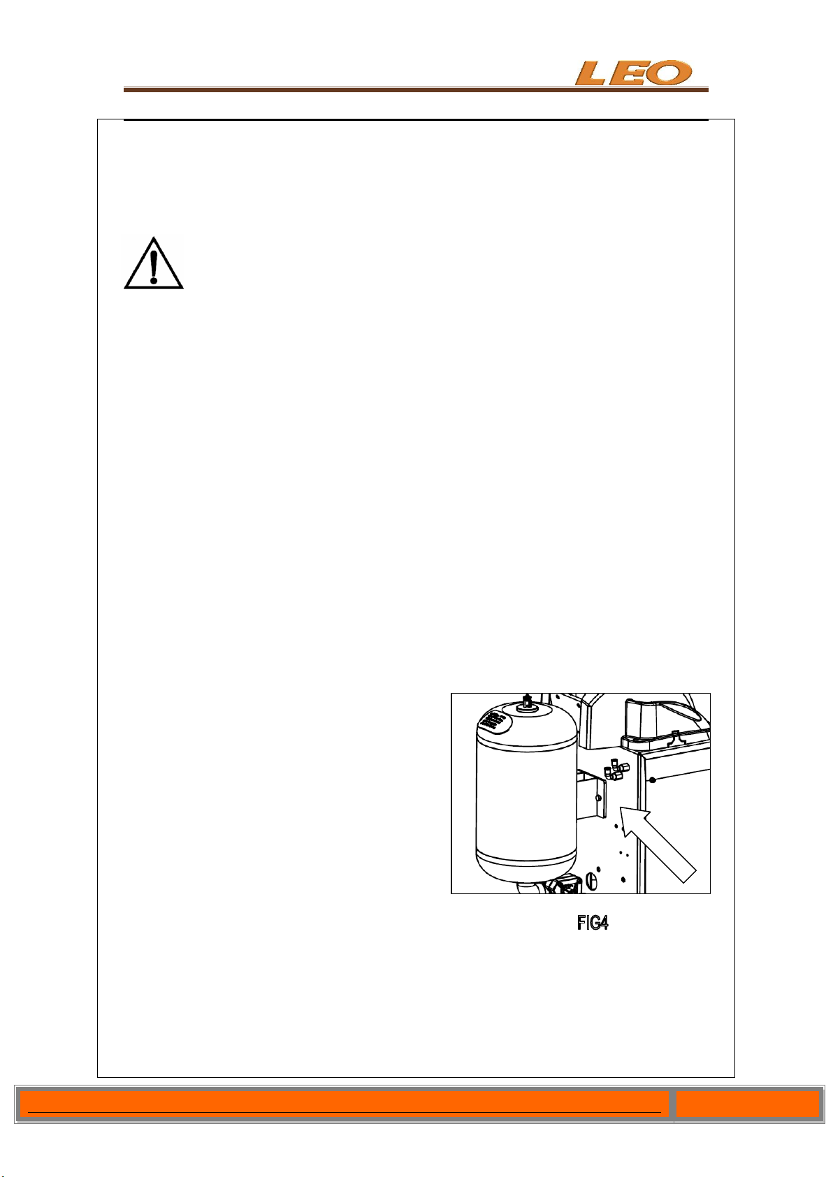
3.2.1 Installation of the air tank
Remvoe the side panel and use 2 pcs M8x25
bolts to connect the air tank at the rear of the
body.
Use the flat washer(GB95-87)and elastic
washer(GB93-87) and nut (GB6170-85) to fix
the air tank in main body of machine.
The condition of the machine after installation is as indicated in Fig4.
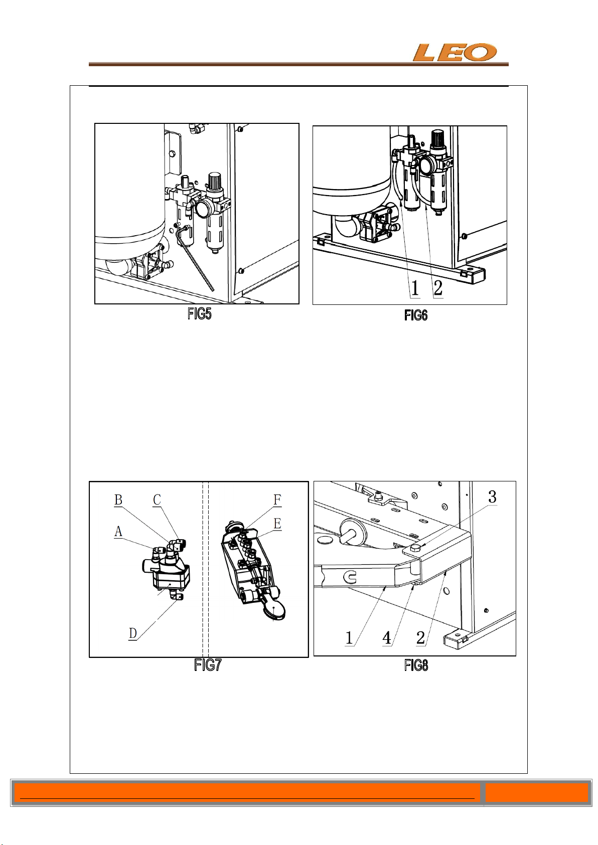
3.2.2 Install the air regulator
Install the air regulator to the right side of the air tank using 2 pieces of M6x10 screw by

- 5 -/ 19
5# Allen key like FIG5.
After installation air regulator, remove the straight connector which connect the two pcs
ofφ8 PU hose like FIG6-1 & FIG6-2. (This connector can avoid the PU hose to back into
the main body.
Connect the PU hose into the connectors of air regulator like FIG6. (if the machine is
without the GT function, just need to connect the hose like FIG6-1).
If the machine has the air tank, connect the holes FIG7-Ato FIG6-2 and FIG7-D to FIG7-F
and FIG7-E to FIG6-2. (The “hole” FIG6-2 is the TEE)
3.2.3 Install the bead breaking arm
As shown in FIG8,align the installation hole of bead breaking arm (FIG8-1)to the
installation hole of bead breaking arm bracket (FIG8-2).
Plug in the pin shaft screw (FIG8-3) and then tighten the lock nut (FIG8-4).
Quick inflation
valve
Quick inflation
pedal assembly

- 6 -/ 19
As shown in Fig9, plug cylinder rod (FIG9-1) into the hole of bead breaking arm slide bush
(FIG9-2).
Twist the adjusting device (FIG9-3) onto the end of cylinder rod.
Hang the spring (FIG9-4)like the FIG9.
3.2.4 Installation of the column assembly
Position the column (FIG10-1) at the upper block of the body (FIG10-2). The surface of
the column that label is stuck on should be forward.
Align the installation hole and plug in the column rotation shaft (FIG10-3), and use the bolt
(FIG10-4) to lock two sides.
Connect of column with the tilt back cylinder:Align the hole (FIG11-2) at the end of the
cylinder rod and the installation hole at the bottom of the column.
Use the 10# Allen key to insert the bolt M12X50 (FIG11-1) to the body upper base like

- 7 -/ 19
FIG11.
Connect the column and the tilt cylinder then fix them using nuts (FIG11-3).
3.2.5 Connect the inflation gun or inflation gauge.
Take out the inflation gun then connect it
the open nut and tighten it. Hang the gun to
the hook after installation.
Install the inflation gauge (FIG13-3): fix it
to the installation hole at the side of column
using two pcs M6 screws(GB70-85). Then
connect theφ8 hose (FIG13-1) on inflation
gauge to the elbow (FIG13-2) on the machine
body back (FIG13).
3.3 Air test:
Column tilt back:Connect the air and press down the lock valve button(FIG3-3)to lock the
horizontal arm. Step down column tilt pedal(FIG3-10)and the column tilt back by 25º.
The tilt speed has been setup before ex-work at about 2seconds.After longtime of use,
the speed will be fast or slow and on this condition, you can use the speed valve at the
heads of the push-out cylinder to adjust. Loose the nut and turn adjust screw clockwise,
the speed will be slow and it will be slow if counterclockwise, tight the nut after adjust.
When the machine out of the factory, the air
source fitting has been adjusted well and if you
need to change, you can readjust.
Before the machine out of the factory, the air
regulator has been adjusted well and can be
re-adjust if need.Adjust the pressure: lift-up the
adjusting knob (FIG19-1) and rotate it
clockwise, the pressure will raise. Otherwise,
decline. Press down the adjusting knob after
adjusting.
Adjust the oil feed: twist the adjusting screw
(FIG19-2) clockwise using the screw driver to
slow the dripping speed and otherwise, quicken
it.

- 8 -/ 19
CHAPTER 4 DEMOUNT AND MOUNT TIRE
Note: the operator must be trained and qualified then allow to operate the tire
changer.Need to use the proper device and tools, wear the protective clothes, and
use the proper safety precautions, like goggle, earplug, and safety shoe and so on.
4.1 BASIC PRINCIPLE
In order to avoid damage the rim, especially the alloy rim, when mount and demount the
ire, must use the specified crowbar.
In order to facilitate the removal and protection the tire and rim, between the tire and rim,
at the position which the bead break blade insert to, need to lubricate using industrial
lubricants or soap water.
For certain types of tires, pay attention to the tire wall and the rotation direction marked on
the tire.
The tire size must be suitable for the rim to mount.
Before mount and demount the tire, need to check whether the rim had damage
(deformation or surface of the outside of the rim, rim axial for radial beat is too big,
corrosion or overall wear).
In any case, pay attention to the mounting and demounting request of the special tire from
the tire manufacturers.
When inflate the tire, to increase the pressure uniformly and pay attention to the tire edge
situation.
4.2DEMOUNT TIRE
Deflate the air in the tire completely and
pull out the core. Use the special tool to
detach the weight on the rim. Place the tire
between then bead breaking blade and
tire pressing runner clog(FIG15).
Then step down the tire press
pedal(FIG3-11) to detach the rim from the
tire. Repeat the same operation on the
other parts of the tire to make the tire
completely detached from the rim.
Move the hexangular shaft to the working position to make the demount tool close to the
rim of the wheel. The cylindrical roller in the demount tool will contact with the external rim
of the rim and the bottom of the demount tool will contact with the surface of the rim.

- 9 -/ 19
Press the lock handle press button(FIG3-3)
to lock horizontal arm and hexangular shaft and
the hexangular shaft will automatically move
upwards. The quadric shaft will automatically
backward a little to make the demount tool
detached from the rim of the rim to avoid the
damage on the rim(FIG16).
NOTE: The angle of the demount tool has been
calibrated according to the standard rim (14"). If
handling the extra-big or extra-small rim, you
can reposition.
Use the crowbar to detach until the lip to the hump of the demount tool (FIG17). Step the
turntable rotation pedal(FIG3-12) to rotate the turntable clockwise until the rim of the wheel fall
off.
If the demount of the tire is jammed, please stop the machine immediately and
then lift up the pedal to let the turntable rotate counterclockwise to remove the
resistance!
Take out the tube and then move up the lower lip to contact with the upper edge of the rim
and detach another lip (FIG18). Step the column tilt pedal (FIG3-9) and the column tilt
backwards and at this moment, you can take off the tire.
4.3Mount tire
Clean up the oil and rust on the rim and lock the rim on the turntable.
Spread the lubrication liquid or soap liquid around the lip. Tilt the tire against the rim and
keep the front end upwards. Press down the column tilt pedal (FIG3-9) to make the
column return to the original position. Move the demount head to firmly contacted rim
(FIG16). Position the left of the lip above the tail of the demount tool and the right under
the hump of the demount tool (FIG18).

- 10 -/ 19
Press down the right side of the tire as hard as you can and step turntable pedal (FIG3-12)
to rotate the turntable clockwise to guide the lip into the tire detach slot completely.
If there is tube, raise up the demount tool and put in the tube and position the core.
Mount the demount tool again. Adjust the
position of the upper lip. Use the assistant
press roller and press to press the side of the
tire to make partial of the lip into the tire
detaching slot (FIG24). Step the turntable
rotation pedal to rotate the tire. At this moment,
continue pressing the lip just mounted on the
rim.
When 10~15cmof the tire not into the rim,
change to the step mode. And observe the condition of the tire to avoid the tear of the tire.
Once you feel there is any tear on the tire, release the pedal at once. Then lift up the
pedal by instep to make the motor rotate reverse. Make the tire restore to the original
condition to mount again.
4.4 Inflation
NOTE: When inflating the tire, please be carefully and series obey the operation process.
Check the air route to see if the air connection is OK. This machine is equipped with an
inflation device for monitoring the inflation of the tire and the inflation pressure.
Loose the tire from the turntable.
Connect the inflation hose with the tire air core.
In the process of inflation, you should repeat stepping the inflation pedal. Confirm the
pressure indicated on the pressure gauge not exceed the scope specified by the

- 11 -/ 19
manufacturer. In this machine, there is a pressure decrease valve to keep theinflation
pressure not exceed 3.5bar.
For tubeless wheel with lax tire, the common inflation is invalid and can use the quick
inflation then common inflation. (The quick inflation function is not standard configuration
and need to special order).
Step down the inflation pedalto the bottom position (second gear) and quickly release the
pedal when the tireis full to the position of the first gear.
Note: the machine equips the reducing valve and set the pressure value at 3.5 bar. Customers
can get different inflation pressure by adjusting the pressure decrease valve according to their
own requirement.If the inflation pressure too high, you can press down the deflation press
button on the inflation device to reach the required air pressure.
Warning! Explosive!
When inflation, you must follow the above safety operation and abide by the following
instruction:
Carefully check is the size of the rim same to the size of the tire and also check the wear
condition of the tire to secure there is no damage before inflation.
When the inflation pressure is relatively high, you should remove the tire from the
machine and inflate in the protective cover.
When inflate the tire, be carefully, keep your hands and body far away from the tire.
Chapter 5 Repair and maintenance

- 12 -/ 19
Note:Only the professional personnel can repair. Before any operations of repair
and maintenance, you should power off and the power plug should be monitored
by the repair personnel, meanwhile switch the pneumatic source and deflate the
residual gas.
To correct use the tire changer and prolong its life,repair and maintenance in accordance with
the operation manual is necessary. Or the running and reliability of the machine will be effected
and the operator or the personnel around the machine will be injured.
5.1 The following parts will be maintained monthly:
Keep the clean of machine and working site.
Use the diesel oil to wash the hexangular shaft and quadrichorizontal arm (Fig20).
Use the diesel oil to clean the turntable jaw and guide railand use the Lithium grease to
lubricate.
Periodically check the height of the in the oil fogger. If itis lower than the oil scale, please
fill in the SAE30 grease. Periodically drill out the water and impurity in the oil-water
separator.
Periodically check and adjust the tension force of the transmission belt and properly
adjust the adjustable nuts at the A and B position to adjust the tension of the belt.
Check all the connecting part and tight the loose bolts.
5.1 The adjustment on the clearance between the tool head and rim.
Switch off the pneumatic source and detach the protective cover on the hexangular
shaft.If the clearance if too much, we can adjust the nuts (Fig21-A) on the vertical

-13 -/ 19
hexangular shaft downward by 16# spanner;If the clearance if too small we can adjust the
nuts on the vertical hexangular shaft upward.
Switch off the air source and detach the protective cover at the upper end of the horizontal
arm.Use 5# spanner to loosen the lock nut (Fig21-C)on the M6 screw at the two
end.Adjust the M6 screw,meanwhile use your hand to push the quadric shaft until it runs
smooth and thenlock the nut.Use the spanner to adjust the screwin the middle and
meanwhile lock the horizontal arm and observe the displacement. When the displacement
is 2mm,lock the nut.
If the square locking plate cannot lock firmly, adjust the taper locking pole.(FIG21-D)
CHAPTER 6 TRANSPORTATION
When transport the machine must apply the original package and place according to the mark
on the package. The machine must be transported by the forklift with the corresponding
tonnage(Fig22)and the stacked layer will not exceed 3layers.

- 14 -/ 19
CHAPTER 7 ELECTCTRICAL AND PENUMATIC DRAWING
7.1 220V ELECTRICAL PRINCIPLE DRAWING

- 15 -/ 19
7.4 PNEUMATIC PRINCIPLE DRAWING
Table of contents
Popular Tyre Changer manuals by other brands

Pittsburgh
Pittsburgh Bead Breaker Owner's manual & safety instructions

John Bean
John Bean EHP System IV-E Operator's manual

Ranger Products
Ranger Products R23 Installation and operation manual

AMSAN
AMSAN AM-TC10626LA manual

Pro-tec
Pro-tec TC-512A Installation, operation & maintenance manual

Unitrol
Unitrol MANAGER manual