2021.06 / o
8
Electric Power Generation Installation and maintenance
LSA 42.3
Low Voltage Alternator - 4 pole
4803 en -
3.2 - Checks prior to rst use
• Electrical checks
Under no circumstances should an
alternator, new or otherwise, be operated
if the insulation is less than 1 megohm
for the stator and 100,000 ohms for the
other windings.
There are 2 possible methods for restoring
the above minimum values.
a) Dry out the machine for 24 hours in a
drying oven at a temperature of 110 °C
(without the regulator).
b) Blow hot air into the air intake, having
made sure that the machine is rotating with
the exciter eld disconnected.
Note : Prolonged standstill
In order to avoid these problems, we
recommend the use of space heaters, as
well as turning over the machine from time
to time. Space heaters are only really
eective if they are working continuously
while the machine is stopped.
Ensure that the alternator has the degree
of protection matching the dened
environmental conditions.
• Mechanical checks
Before starting the machine for the rst time,
check that:
- all xing bolts are tight,
- the length of bolt and the tightening torque
are correct,
- the cooling air is drawn in freely,
- the protective grille and housing are cor-
rectly in place,
- the standard direction of rotation is clock-
wise as seen from the drive end (phase
rotation in order 1 - 2 - 3).
For anti-clockwise rotation, swap 2 and 3.
- the winding connection corresponds to the
site operating voltage (see section 3.3).
3.3 - Terminal connection diagrams
To modify the connection, change the
position of the stator cables on the terminals.
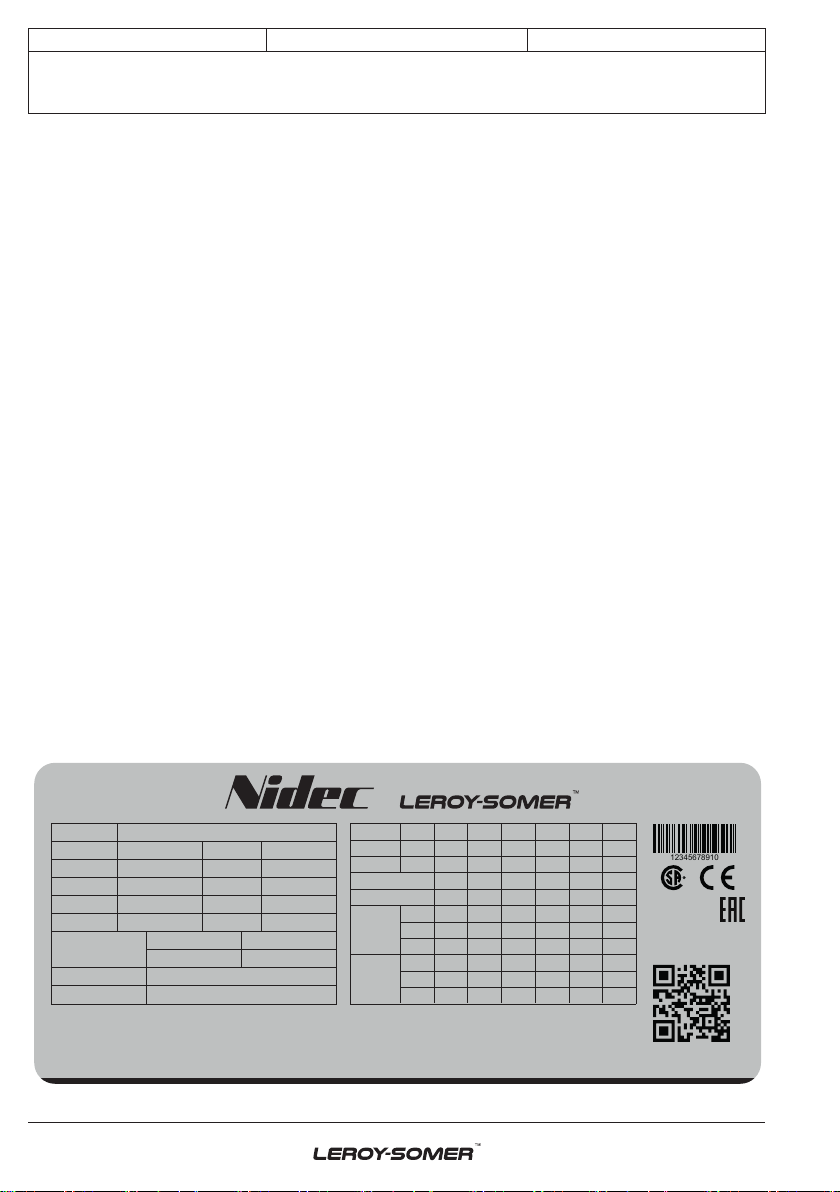
The winding code is specied on the
nameplate.
Any intervention on the alternator
terminals during reconnection or checks
should be performed with the machine
stopped. In no case should the internal
connections in the terminal box be
subjected to stresses due to cables
connected by the user.
When the alternator’s power output is
ensured directly through cables, these
must be connected before start-up.
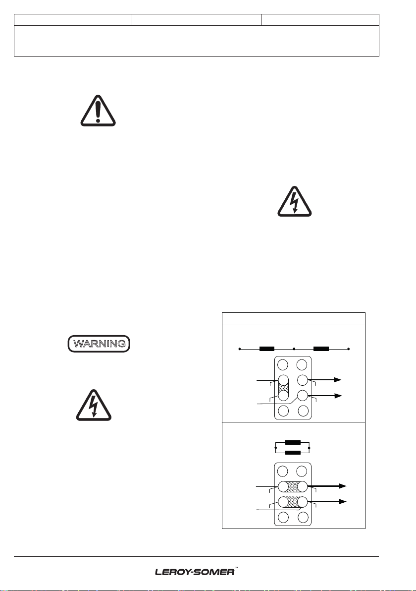
• SHUNT dedicated single-phase 4-wire
T1 T2 T3 T4
T3 T4
T1 T2
T4
T1
T2
T3
110V
0V
L
L
M
T2
T3
T4
T1
L
L
110V
0V
R221R221
Connection
Series connection
Parallel connection
DE
NDE
DE
NDE