7
Operation
Before Operation
As with all mechanical tools, use reasonable care during
operation. Inspect the work area and machine before
operation. Be sure that all operators of this equipment are
trained in safety and general use. Be sure all operators have
read and understand the Owner's Manual.
Before operation, always:
1. Check the unit for loose hardware.
2. Check the engine oil level. Add oil if necessary.
3. Check the engine gasoline level. Add gasoline if
necessary. Replace old or bad gasoline.
4. Inspect the operation area conditions. Sod should not be
too dry, nor too wet. Sod should be damp. Sod that is too
dry can damage the blade. Sod that is too wet may cause
slippage.
5. Inspect the operation area for obstacles. Remove
obstacles that may damage the blade.
General Operation
1. Position the unit on sufficiently firm (but damp), flat soil.
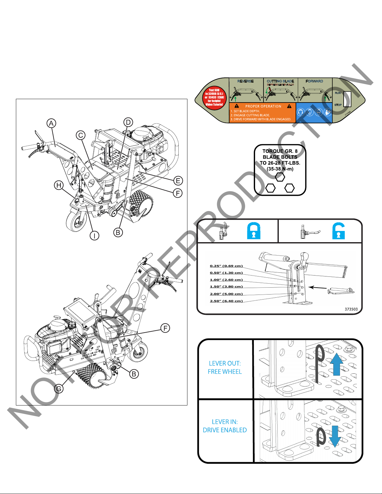
2. Select desired cutting depth. Insert the depth control pin
into the desired position on the blade height adjuster. See
the Blade Height Adjustertopic under the Features and
Controls section.
Note:Do not adjust cutting depth during operation. Park, turn
off the unit, then adjust cutting depth.
Note:Sod should be cut leaving a minimum amount of dirt
(1/4”-3/8”) attached to the roots. This minimizes its weight for
removal and encourages faster growth when reused.
3. Start the engine. Push the throttle lever down completely,
then pull the recoil handle to start the engine. Under cold
conditions, choke the engine before attempting to start.
See the Engine Controls section.
4. Check the unit for excessive vibration. If there is no
excessive vibration, continue to the next step.
WARNING
Do not operate the unit if excessive vibration occurs. If
excessive vibration occurs, immediately shut off the engine.
Check for a damaged or worn blade, loose hardware, or
lodged foreign objects. If you cannot find the source of
excessive vibration, contact your Authorized Service Dealer.
5. To begin cutting operation, firmly grasp both handles and
fully depress the blade engage lever. Rock back on the
handles to allow the blade to cut into the sod. Keep the
blade engage lever fully depressed at all times during
operation.
6. Begin driving the unit. Depress the right handle to move
forward. Depress the left handle to move in reverse. As
ground conditions allow, increase or decrease the ground
speed of the unit. To gradually increase speed, gradually
depress the lever. The unit operates at maximum speed
with the lever fully depressed. The unit operates at
minimum speed with the lever minimally depressed.
7. Cut sod in strips. At the end of a strip, fully release the
blade engage lever. Then, fully release the drive lever
until the unit stops. Release the cam lever on the blade
height adjuster to unlock the blade. Pull up on the height
adjuster handle to raise the blade out of the sod. Lock the
blade into place.
8. Drive the unit to the next strip of sod to be cut. Stop the
unit, and lower the blade to desired depth using the blade
height adjuster. Resume cutting by fully depressing the
blade engage lever.
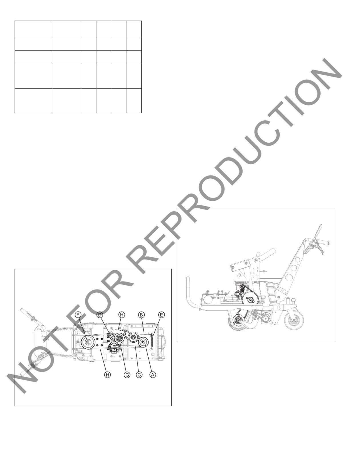
Periodic Maintenance
The blade, drive belts, and chains are normal wear items.
Inspect these items regularly and replace if worn. For engine
maintenance, please refer to the engine manufacturer
owner's manual.
Maintenance
Operation
Each Use 25
Hrs
50
Hrs
100
Hrs
200
Hrs
Check engine
oil.
X
Check gasoline. X
Check for
loose, worn, or
damaged parts.
X
Check for
excessive
vibration.
X
Replace engine
oil.
X
Lubricate and
check chain
tension.
X
Sharpen cutting
blade.
X
Inspect axle
area between
wheels for debris
buildup. Clean if
necessary.*
X
Clean engine air
filter.
X
Grease jackshaft
bearings.
X
Check traction
belts. Adjust
or replace if
necessary.
XXX
Check rear
castor rod.
Adjust or replace
if necessary.
XXX
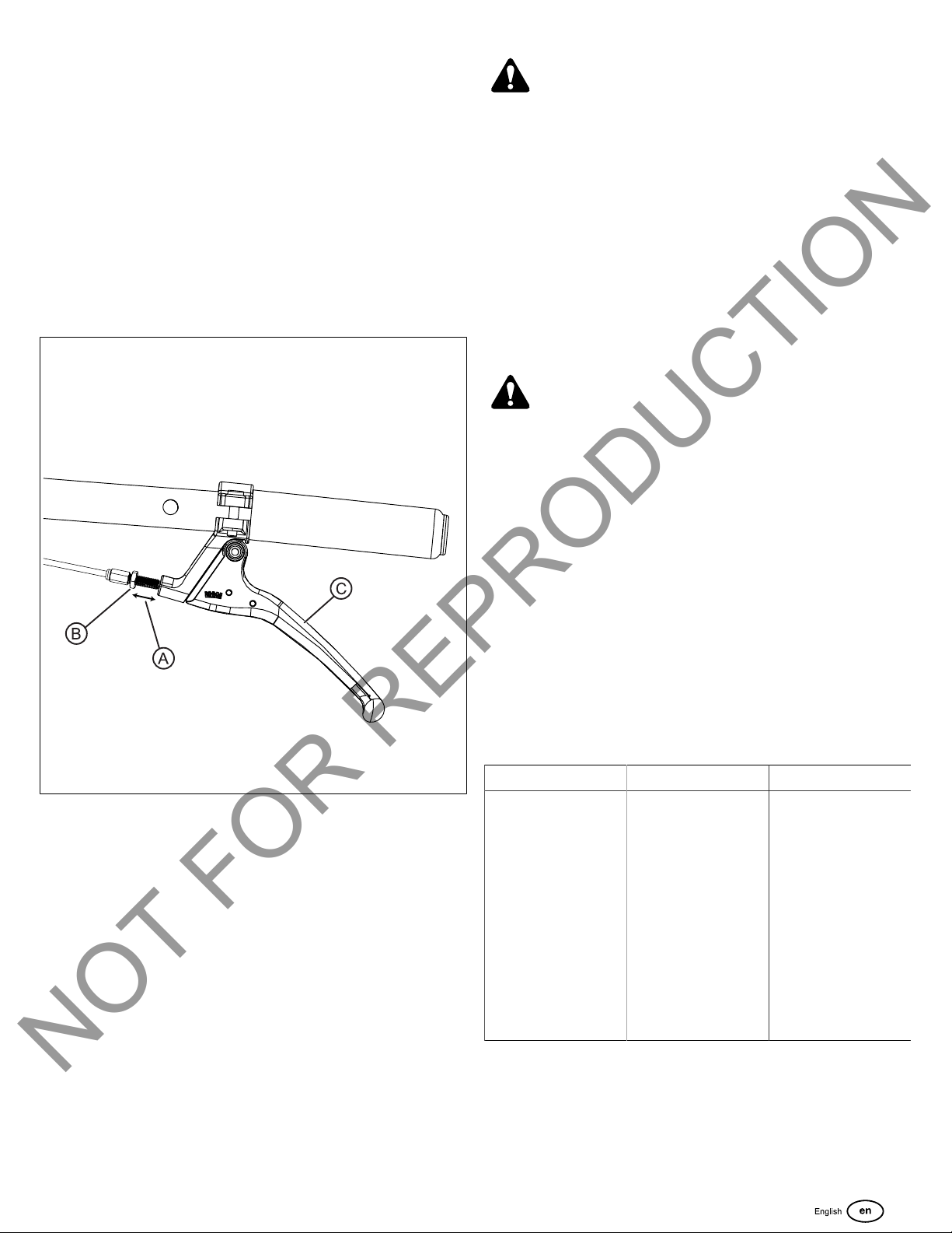
Check drive
cables for wear.
Adjust or replace
if necessary.
XXX