manuals.online logo
Brands
  1. Home
  2. •
  3. Brands
  4. •
  5. Landoll
  6. •
  7. Farm Equipment
  8. •
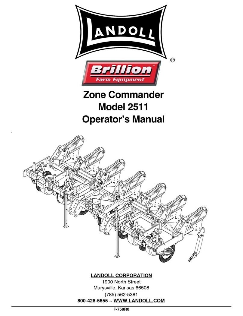
  9. Landoll Brillion 2512 Zone Commander User manual

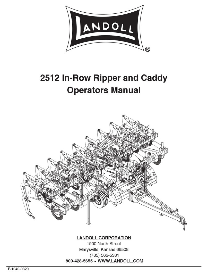
Landoll Brillion 2512 Zone Commander User manual

2512 Zone Commander and Caddy
FOR UNITS SHIPPED AFTER DECEMBER 1, 2020
(SN: 25M201237 AND ABOVE)
PREVIOUS UNITS SHOULD REFERENCE F-1040-0320
Operators Manual
LANDOLL COMPANY, LLC
1900 North Street
Marysville, Kansas 66508
(785) 562-5381
800-428-5655 ~WWW.LANDOLL.COM
F-1049-0421
®
1-2 F-1049-0421
Manuals for the 2512 Zone Commander
F-1048 2512 Zone Commander Parts Manual
F-1049 2512 Zone Commander Operators Manual
F-1076 Caddy Parts Manual (ONLY)
i
Table of Contents
1 Introduction and Safety Information
Understanding Safety Statements . . . . . . . . . . . . . . . . . . . . . . . . . . . . . . . . . . . . . . . . . . . . . 1-2
Decal Safety . . . . . . . . . . . . . . . . . . . . . . . . . . . . . . . . . . . . . . . . . . . . . . . . . . . . . . . . . . . . . 1-2
Transporting Safety . . . . . . . . . . . . . . . . . . . . . . . . . . . . . . . . . . . . . . . . . . . . . . . . . . . . . . . . 1-3
Attaching, Detaching, and Storage . . . . . . . . . . . . . . . . . . . . . . . . . . . . . . . . . . . . . . . . . . . . 1-3
Maintenance Safety . . . . . . . . . . . . . . . . . . . . . . . . . . . . . . . . . . . . . . . . . . . . . . . . . . . . . . . . 1-3
High Pressure Fluid Safety . . . . . . . . . . . . . . . . . . . . . . . . . . . . . . . . . . . . . . . . . . . . . . . . . . 1-3
Protective Equipment . . . . . . . . . . . . . . . . . . . . . . . . . . . . . . . . . . . . . . . . . . . . . . . . . . . . . . 1-3
Chemical Safety . . . . . . . . . . . . . . . . . . . . . . . . . . . . . . . . . . . . . . . . . . . . . . . . . . . . . . . . . . 1-3
Prepare for Emergencies . . . . . . . . . . . . . . . . . . . . . . . . . . . . . . . . . . . . . . . . . . . . . . . . . . . 1-3
Tire Safety . . . . . . . . . . . . . . . . . . . . . . . . . . . . . . . . . . . . . . . . . . . . . . . . . . . . . . . . . . . . . . . 1-4
Safety Chain . . . . . . . . . . . . . . . . . . . . . . . . . . . . . . . . . . . . . . . . . . . . . . . . . . . . . . . . . . . . . 1-4
2 Standard Specifications
Model Specifications . . . . . . . . . . . . . . . . . . . . . . . . . . . . . . . . . . . . . . . . . . . . . . . . . . . . . . . 2-1
General Torque Specifications (rev. 4/97) . . . . . . . . . . . . . . . . . . . . . . . . . . . . . . . . . . . . . . . 2-3
Hydraulic Fitting Torque Specifications . . . . . . . . . . . . . . . . . . . . . . . . . . . . . . . . . . . . . . . . . 2-4
Shank Mounting Dimensions - Rigid . . . . . . . . . . . . . . . . . . . . . . . . . . . . . . . . . . . . . . . . . . . 2-5
Shank Mounting Dimensions - Folding . . . . . . . . . . . . . . . . . . . . . . . . . . . . . . . . . . . . . . . . 2-10
3 Assembly Instructions
Specific Dangers and Warnings . . . . . . . . . . . . . . . . . . . . . . . . . . . . . . . . . . . . . . . . . . . . . . 3-1
Assembly Preparation . . . . . . . . . . . . . . . . . . . . . . . . . . . . . . . . . . . . . . . . . . . . . . . . . . . . . . 3-2
Jackstand Installation . . . . . . . . . . . . . . . . . . . . . . . . . . . . . . . . . . . . . . . . . . . . . . . . . . . . . . 3-2
SMV Bracket Installation . . . . . . . . . . . . . . . . . . . . . . . . . . . . . . . . . . . . . . . . . . . . . . . . . . . . 3-2
Shank Assembly . . . . . . . . . . . . . . . . . . . . . . . . . . . . . . . . . . . . . . . . . . . . . . . . . . . . . . . . . . 3-3
Coverboard Installation . . . . . . . . . . . . . . . . . . . . . . . . . . . . . . . . . . . . . . . . . . . . . . . . . . . . . 3-7
Right Hand & Left Hand Coulter Assemblies . . . . . . . . . . . . . . . . . . . . . . . . . . . . . . . . . . . . 3-7
Gauge Wheel . . . . . . . . . . . . . . . . . . . . . . . . . . . . . . . . . . . . . . . . . . . . . . . . . . . . . . . . . . . . 3-7
Electrical Installation . . . . . . . . . . . . . . . . . . . . . . . . . . . . . . . . . . . . . . . . . . . . . . . . . . . . . . 3-11
General Hydraulic Components - Hydraulic Reset Option . . . . . . . . . . . . . . . . . . . . . . . . . 3-11
Closer Platform (Option) and Features . . . . . . . . . . . . . . . . . . . . . . . . . . . . . . . . . . . . . . . . 3-15
4 Operation and Maintenance
Tractor Preparation . . . . . . . . . . . . . . . . . . . . . . . . . . . . . . . . . . . . . . . . . . . . . . . . . . . . . . . . 4-2
Zone Commander Operation . . . . . . . . . . . . . . . . . . . . . . . . . . . . . . . . . . . . . . . . . . . . . . . . . 4-2
Hydraulic Accumulator Operation . . . . . . . . . . . . . . . . . . . . . . . . . . . . . . . . . . . . . . . . . . . . . 4-2
Attaching to Three-Point Hitch . . . . . . . . . . . . . . . . . . . . . . . . . . . . . . . . . . . . . . . . . . . . . . . 4-3
Attaching to Caddy . . . . . . . . . . . . . . . . . . . . . . . . . . . . . . . . . . . . . . . . . . . . . . . . . . . . . . . . 4-3
Hydraulic Fold System . . . . . . . . . . . . . . . . . . . . . . . . . . . . . . . . . . . . . . . . . . . . . . . . . . . . . 4-5
Field Operation - Three Point Hitch Type . . . . . . . . . . . . . . . . . . . . . . . . . . . . . . . . . . . . . . . 4-6
Wheel Bearing Maintenance . . . . . . . . . . . . . . . . . . . . . . . . . . . . . . . . . . . . . . . . . . . . . . . . . 4-6
Coulter Spring Adjustment . . . . . . . . . . . . . . . . . . . . . . . . . . . . . . . . . . . . . . . . . . . . . . . . . . 4-6
Lubrication . . . . . . . . . . . . . . . . . . . . . . . . . . . . . . . . . . . . . . . . . . . . . . . . . . . . . . . . . . . . . . . 4-6
Storage . . . . . . . . . . . . . . . . . . . . . . . . . . . . . . . . . . . . . . . . . . . . . . . . . . . . . . . . . . . . . . . . . 4-6
5 Troubleshooting Guide
ii F-1049-0421
TABLE OF CONTENTS
F-1049-0421 1-1
TABLE OF CONTENTS Chapter 1
Introduction and Safety Information
The Landoll Model 2512 Rigid & Folding Zone Commander are quality products designed to give years of trouble free
performance. By following each section of this manual, your system will perform as designed for you and your
operation.
CHAPTER 1 Gives basic instructions on the use of this manual and understanding the safety
statements.
CHAPTER 2 Gives product specifications for the equipment. These specifications supply lengths and
measures for your equipment. A Standard Bolt Torque Table is provided to give
guidelines for bolt torques to be used when servicing this product.
CHAPTER 3 Contains assembly instructions for your 2512 Rigid & Folding Zone Commander. When
these procedures are correctly followed, your equipment should provide you years of
trouble-free operation and service.
CHAPTER 4 Instructs how to operate your equipment before using it, and describes adjustments
needed. Gives practical advice for the care and maintenance of your Landoll equipment.
Drawings in this section locate adjustment points on the equipment.
IF YOU HAVE ANY QUESTIONS CONTACT:
LANDOLL COMPANY, LLC
1900 NORTH STREET
MARYSVILLE, KANSAS 66508
PHONE # (785) 562-5381 or (800) 428-5655
OR
FAX # (888) 527-3909
CHAPTER 5 Is a troubleshooting guide to aid in diagnosing and solving problems with the Zone
Commander.
PARTS MANUAL Is a separate manual showing the various assemblies, subassemblies, and systems.
Refer to that manual when ordering Landoll replacement parts. Order parts from your
Landoll dealer.
WARRANTY The Warranty Registration form is filled out at the time of sale. For questions regarding
the product registration, please contact the dealer where the implement was purchased.
NOTE: IMPROPER ASSEMBLY, MODIFICATION, OR MAINTENANCE OF YOUR
LANDOLL MACHINE CAN VOID YOUR WARRANTY.
COMMENTS Address comments or questions regarding this publication to:
LANDOLL COMPANY, LLC
1900 NORTH STREET
MARYSVILLE, KANSAS 66508
ATTENTION: PUBLICATIONS - DEPT. 55
1-2 F-1049-0421
INTRODUCTION AND SAFETY INFORMATION
TABLE OF CONTENTS
Understanding Safety
Statements
You will find various types of safety information on the
following pages and on the machine signs (decals)
attached to the vehicle. This section explains their
meaning.
The Safety Alert Symbol means ATTENTION! YOUR
SAFETY IS INVOLVED!
NOTE
Means that failure to follow these instructions could
cause damage to the equipment or cause it to operate
improperly.
NOTICE
CAUTION
WARNING
DANGER
NOTE
Make sure you read and understand the information
contained in this manual and on the machine signs
(decals) before you attempt to operate or maintain this
vehicle.
The safety statements contained in this manual relate to
the operation of the Model 2512 Rigid & Folding Zone
Commander.
Decal Safety
1. Examine safety decals and be sure you have the
correct safety decals for the implement.
2. Keep these signs clean so they can be observed
readily. It is important to keep these decals cleaned
more frequently than the implement. Wash with soap
and water or a cleaning solution as required.
3. Replace decals that become damaged or lost. Also,
be sure that any new implement components
installed during repair include decals which are
assigned to them by the manufacturer.
4. When applying decals to the implement, be sure to
clean the surface to remove any dirt or residue.
Where possible, sign placement should protect the
sign from abrasion, damage, or obstruction from
mud, dirt, oil etc.
Special notice - read and thoroughly understand.
Caution means serious equipment or other
property damage can occur if instructions on this
label are not properly followed.
Warning means serious injury or death can occur
if safety measures or instructions on this label
are not properly followed.
Danger means a life-threatening situation exists.
Death can occur if safety measures or
instructions on this label are not properly
followed.

INTRODUCTION AND SAFETY INFORMATION
F-1049-0421 1-3
TABLE OF CONTENTS
DANGER
Transporting Safety
IMPORTANT
It is the responsibility of the owner/operator to
comply with all state and local laws.
1. When transporting the implement on a road or
highway, use adequate warning symbols, reflectors,
lights and slow moving vehicle sign as required. Slow
moving tractors and towed implements can create a
hazard when driven on public roads. They are
difficult to see, especially at night.
2. Do not tow an implement that, when fully loaded,
weighs more than 1.5 times the weight of the towing
vehicle.
3. Carry reflectors or flags to mark the tractor and
implement in case of breakdown on the road.
4. Do not transport at speeds over 20 MPH under good
conditions. Never travel at a speed which does not
allow adequate control of steering and stopping.
Reduce speed if towed load is not equipped with
brakes.
5. Avoid sudden stops or turns because the weight of
the implement may cause the operator to lose control
of the tractor. Use a tractor heavier than the
implement.
6. Use caution when towing behind articulated steering
tractors; fast or sharp turns may cause the implement
to shift sideways.
7. Keep clear of overhead power lines and other
obstructions when transporting. Know the transport
height and width of your implement.
Attaching, Detaching, and
Storage
1. Do not stand between the tractor and implement
when attaching or detaching implement unless both
are not moving.
2. Block implement so it will not roll when unhitched
from the tractor.
3. Store in an area where children normally do not play.
Maintenance Safety
1. Understand the procedure before doing the work.
Use proper tools and equipment.
2. Make sure all moving parts have stopped.
3. Do not make adjustments or lubricate implement
while it is in motion.
4. Block the implement so it will not roll when working
on or under it to prevent injury.
High Pressure Fluid Safety
1. Escaping fluid under pressure can be nearly invisible
and have enough force to penetrate the skin causing
serious injury. Use a piece of cardboard, rather than
hands, to search for suspected leaks.
2. Any fluid injected into the skin must be surgically
removed within a few hours or gangrene may result.
3. Avoid the hazard by relieving pressure before
disconnecting hydraulic lines.
Protective Equipment
1. Wear protective clothing and equipment.
2. Wear clothing and equipment appropriate for the job.
Avoid loose fitting clothing.
3. Because prolonged exposure to loud noise can
cause hearing impairment or hearing loss, wear
suitable hearing protection, such as earmuffs or
earplugs.
Chemical Safety
1. Agricultural chemicals can be dangerous. Improper
use can seriously injure persons, animals, plants, soil
and property.
2. Read chemical manufactures instructions and store
or dispose of unused chemicals as specified.
3. Handle chemicals with care and avoid inhaling
smoke from any type of chemical fire.
4. Store or dispose of unused chemicals as specified by
the chemical manufacturer.
Prepare for Emergencies
1. Keep a First Aid Kit and Fire Extinguisher handy.
2. Keep emergency numbers for doctor, ambulance,
hospital and fire department near the phone.
• Do not allow anyone to ride on the tractor or
implement. Riders could be struck by foreign
objects or thrown from the implement.
• Never allow children to operate equipment.
• Keep bystanders away from implement during
operation.
1-4 F-1049-0421
INTRODUCTION AND SAFETY INFORMATION
TABLE OF CONTENTS
Tire Safety
1. Tire changing can be dangerous and should be
performed by trained personnel using correct tools
and equipment.
2. When inflating tires, use a clip-on chuck and
extension hose long enough to allow you to stand to
one side, not in front of or over the tire assembly.
Use a safety cage if available.
3. When removing and installing wheels use
wheel-handling equipment adequate for the weight
involved.
Safety Chain
1. Use a chain with a strength rating equal to or greater
than the gross weight of towed machinery, which is
10,100 pounds minimum in accordance with ASAE
S338.2 specifications. If two or more implements are
pulled in tandem, a larger chain may be required.
Chain capacity must be greater that the TOTAL
weight of all towed implements.
2. A second chain should be used between each
implement.
3. Attach the chain to the tractor drawbar support or
specified anchor location. Allow only enough slack in
the chain to permit turning. The distance from hitch
pin to attachment point or intermediate support point
should not exceed 9 inches.
4. Replace the chain if any links or end fittings are
broken, stretched or damaged.
5. Do not use a safety chain for towing.
F-1049-0421 2-1
TABLE OF CONTENTS Chapter 2
Standard Specifications
Model Specifications
2511N Rigid Zone Commander
Model Number of
Shanks Frame Type Frame Configuration Transport
Width
Estimated
Weight
2511N-3-30 3 RIGID 107 (IN) RIGID 110" (9' - 2") 3,357
W/2 GAUGE WHEEL
2511N-4-30 4 RIGID 107 (IN) RIGID 110" (9' - 2") 3,849
W/2 GAUGE WHEEL
2511N-5-30 5 RIGID 107 (IN) RIGID CT,
(2) 13 (IN) EXT 140" (11' - 8") 4,725
W/2 GAUGE WHEEL
2512 Rigid and Folding Zone Commander (Caddy Optional)
Model Number of
Shanks Frame Type Frame Configuration Transport
Width
Estimated
Weight
2512-4-30 4 RIGID 135 (IN) RIGID 149" (12' - 5") 5,636
W/2 GAUGE WHEEL
2512-5-30 5 RIGID 135 (IN) RIGID 136" (11' - 4") 6,398
W/2 GAUGE WHEEL
2512-6-30 6 RIGID - 1-4-1 135 (IN) RIGID CT,
(2) 13 (IN) EXT 161" (13' - 5") 8,209
W/2 GAUGE WHEEL
2512-7-30 7 RIGID - 1-5-1 135 (IN) RIGID CT,
(2) 28 (IN) EXT 190" (15' - 10") 9,406
W/2 GAUGE WHEEL
2512-8-30 8 RIGID - 2-4-2 135 (IN) RIGID CT,
(2) 44 (IN) WING 223" (18' - 6") 10,473
W/2 GAUGE WHEEL
2512F-7-30 7 FOLDING - 1-5-1 150 (IN) RIGID CT,
(2) 24 (IN) WING 167" (13' - 11") 10,422
W/2 GAUGE WHEEL
2512F-8-30 8 FOLDING - 1-6-1 180 (IN) RIGID CT,
(2) 24 (IN) WING 197" (16' - 5") 11,559
W/2 GAUGE WHEEL
2512F-9-30 9 FOLDING - 2-5-2 150 (IN) RIGID CT,
(2) 52 (IN) WING 167" (13' - 11") 12,721 W/2 GAUGE
WHEEL ON WINGS
2512 Folding Zone Commander (Caddy ONLY)
Model Number of
Shanks Shank Spacing Shank Extensions Transport
Width Estimated Weight
2512F-10-30 10 FOLDING - 2-6-2 180 (IN) CENTER CT,
(2) 52 (IN) WING 197" (16' - 5") 13,872 W/2 GAUGE
WHEEL ON WINGS
2512F-11-30 11 FOLDING - 2-7-2 210 (IN) CENTER CT,
(2) 52 (IN) WING 227" (18' - 11") 14,924 W/2 GAUGE
WHEEL ON WINGS
2512F-12-30 12 FOLDING - 3-6-3 150 (IN) CENTER CT,
(2) 82 (IN) WING 197" (16' - 5") 16,045 W/2 GAUGE
WHEEL ON WINGS
2512F-13-30 13 FOLDING - 3-7-3 210 (IN) CENTER CT,
(2) 82 (IN) WING 227" (18' - 11") 17,097 W/2 GAUGE
WHEEL ON WINGS
2512F-14-30 14 FOLDING - 3-8-3 240 (IN) CENTER CT,
(2) 82 (IN) WING 257" (21' - 5") 18,430 W/2 GAUGE
WHEEL ON WINGS
2512F-15-30 15 FOLDING - 4-7-4 210 (IN) CENTER CT,
(2) 112 (IN) WING 227" (18' - 11") 19,299 W/2 GAUGE
WHEEL ON WINGS
2512F-16-30 16 FOLDING - 4-8-4 240 (IN) CENTER CT,
(2) 112 (IN) WING 257" (21' - 5") 20,731 W/2 GAUGE
WHEEL ON WINGS
2-2 F-1049-0421
STANDARD SPECIFICATIONS
TABLE OF CONTENTS
Tire Inflation
Model Tire Size Ply/Load Rating Inflation Pressure (Psi) (Max.)
Caddy STD IF 320/70R15 144 70 psi
Caddy HD VF 385/65R22.5 163 70 psi
Gauge Wheels IF280/70R15 134 64 psi
Gauge Wheels 20.5 X 8.0 X 10 D 70 psi
Recommended Torque Specification For Lug Bolts and Nuts
Bolt Size Torque (FT. LBS.)
9/16-18 (Heavy Duty Disc) 80 - 90 FT. LBS.
STANDARD SPECIFICATIONS
F-1049-0421 2-3
TABLE OF CONTENTS
General Torque Specifications
(rev. 4/97)
Figure 2-1: General Torque Specifications
TORQUE SPECIFIED IN FOOT POUNDS - This chart provides tightening torques for general purpose applications when
special torques are not specified on process or drawing. Assembly torques apply to plated nuts and capscrews assembled
without supplemental lubrication (as received condition). They do not apply if special graphite moly-disulfide or other extreme
pressure lubricants are used. When fasteners are dry (solvent cleaned) add 33% to as received condition torque. Bolt head
identification marks indicate grade and may vary from manufacturer to manufacturer. Thick nuts must be used on grade 8
capscrews. Use value in [ ] if using prevailing torque nuts.
UNC SIZE SAE Grade 2 SAE Grade 5 SAE Grade 8 UNF SIZE SAE Grade 2 SAE Grade 5 SAE Grade 8
1/4-20 4 [5] 6 [7] 9 [11] 1/4-28 5 [6] 7 [9] 10 [12]
5/16-18 8 [10] 13 [13] 18 [22] 5/16-24 9 [11] 14 [17] 20 [25]
3/8-16 15 [19] 23 [29] 35 [42] 3/8-24 17 [21] 25 [31] 35 [44]
7/16-14 24 [30] 35 [43] 55 [62] 7/16-20 27 [34] 40 [50] 60 [75]
1/2-13 35 [43] 55 [62] 80 [100] 1/2-20 40 [50] 65 [81] 90 [112]
9/16-12 55 [62] 80 [100] 110 [137] 9/16-18 60 [75] 90 [112] 130 [162]
5/8-11 75 [94] 110 [137] 170 [212] 5/8-18 85 [106] 130 [162] 180 [225]
3/4/10 130 [162] 200 [250] 280 [350] 3/4-16 150 [188] 220 [275] 320 [400]
7/8-9 125 [156] 320 [400] 460 [575] 7/8-14 140 [175] 360 [450] 500 [625]
1-8 190 [237] 408 [506] 680 [850] 1-14 210 [263] 540 [675] 760 [950]
1-1/8-7 270 [337] 600 [750] 960 [1200] 1-1/8-12 300 [375] 660 [825] 1080 [1350]
1-1/4-7 380 [475] 840 [1050] 1426 [1782] 1-1/4-12 420 [525] 920 [1150] 1500 [1875]
1-3/8-6 490 [612] 1010 [1375] 1780 [2225] 1-3/8-12 560 [700] 1260 [1575] 2010 [2512]
1-1/2-6 650 [812] 1460 [1825] 2360 [2950] 1-1/2-12 730 [912] 1640 [2050] 2660 [3325]
1-3/4-5 736 [920] 1651 [2063] 2678 [3347] 1-3/4-12 920 [1150] 2063 [2579] 3347 [4183]
METRIC:
Coarse thread metric class 10.9 fasteners and class 10.0 nuts and through hardened flat washers, phosphate coated, Rockwell
“C” 38-45. Use value in [ ] if using prevailing torque nuts.
Nominal
thread
diameter
(mm)
Newton
Meters
(Standard
Torque)
Foot
Pounds
(Standard
Torque)
Nominal
Thread
Diameter
(mm)
Newton
Meters
(Standard
Torque)
Foot
Pounds
(Standard
Torque
6 10 [14] 7 [10] 20 385 [450] 290 [335]
7 16 [22] 12 [16] 24 670 [775] 500 [625]
8 23 [32] 17 [24] 27 980 [1105] 730 [825]
10 46 [60] 34 [47] 30 1330 [1470] 990 [1090]
12 80 [125] 60 [75] 33 1790 [1950] 1340 [1450]
14 125 [155] 90 [115] 36 2325 [2515] 1730 [1870]
16 200 [240] 150 [180] 39 3010 [3210] 2240 [2380]
18 275 [330] 205 [245]
2-4 F-1049-0421
STANDARD SPECIFICATIONS
TABLE OF CONTENTS
Hydraulic Fitting Torque Specifications
Figure 2-2: Hydraulic Fitting Torque Specifications
TORQUE IS SPECIFIED IN FOOT POUNDS- 37oJIC, ORS, & ORB (REV. 10/97)
This chart provides tightening torques for general purpose applications when special torques are not specified on process or
drawing. Assembly torques apply to plated nuts and capscrews assembled without supplemental lubrication (as received
condition). They do not apply if special graphite moly-disulfide or other extreme pressure lubricants are used. When fasteners are
dry (solvent cleaned) add 33% to as received condition torque. Bolt head identification marks indicate grade and may vary from
manufacturer to manufacturer. Thick nuts must be used on grade 8 capscrews. Use value in [ ] if using prevailing torque nuts.
Parker Brand Fittings
Dash Size 37 Degree JIC O-Ring (ORS) O-Ring Boss (ORB)
-4 11-13 15-17 13-15
-5 14-16 --------------- 21-23
-6 20-22 34-36 25-29
-8 43-47 58-62 40-44
-10 55-65 100-110 58-62
-12 80-90 134-146 75-85
-16 115-125 202-218 109-121
-20 160-180 248-272 213-237
-24 185-215 303-327 238-262
-32 250-290 -------------- 310-340
Gates Brand Fittings
Dash Size 37 Degree JIC O-Ring (ORS) O-Ring Boss (ORB)
-4 10-11 10-12 14-16
-5 13-15 --------------- ---------------
-6 17-19 18-20 24-26
-8 34-38 32-40 37-44
-10 50-56 46-56 50-60
-12 70-78 65-80 75-83
-14 -------------- 65-80 --------------
-16 94-104 92-105 111-125
-20 124-138 125-140 133-152
-24 156-173 150-180 156-184
-32 219-243 -------------- --------------
Aeroquip Brand Fittings
Dash Size 37 Degree JIC O-Ring (ORS) O-Ring Boss (ORB)
-4 11-12 10-12 14-16
-5 15-16 --------------- 16-20
-6 18-20 18-20 24-26
-8 38-42 32-35 50-60
-10 57-62 46-50 75-80
-12 79-87 65-70 125-135
-14 -------------- -------------- 160-180
-16 108-113 92-100 200-220
-20 127-133 125-140 210-280
-24 158-167 150-165 270-360
-32 245-258 -------------- --------------
STANDARD SPECIFICATIONS
F-1049-0421 2-5
TABLE OF CONTENTS
Shank Mounting Dimensions - Rigid
Figure 2-3: 4-Shank Spacing
9 3/4
30
12 1/2 12 1/2
44 1/4
TRANSPORT WIDTH 149
9 3/4
30
15
30 30
15
2-6 F-1049-0421
STANDARD SPECIFICATIONS
TABLE OF CONTENTS
Figure 2-4: 5-Shank Spacing
30
TRANSPORT WIDTH 136
30
9 3/4
30
30
9 3/4
44 1/4
3030
30
30
STANDARD SPECIFICATIONS
F-1049-0421 2-7
TABLE OF CONTENTS
Figure 2-5: 6-Shank Spacing
30 30 15 15 30 30
30 30
12 1/2
30 30 12 1/2
9 3/4
9 3/4
44 1/4
TRANSPORT WIDTH 161
2-8 F-1049-0421
STANDARD SPECIFICATIONS
TABLE OF CONTENTS
Figure 2-6: 7-Shank Spacing
30 30 30 30 30 30
9 3/49 3/4
44 1/4
TRANSPORT WIDTH 190
30 30 30 30 30 30
STANDARD SPECIFICATIONS
F-1049-0421 2-9
TABLE OF CONTENTS
Figure 2-7: 8-Shank Spacing
30 30 30 30 30 30
12 ½12 ½
44 ¼
TRANSPORT WIDTH 223
9 ¾ 9 ¾
303030303030 1515
2-10 F-1049-0421
STANDARD SPECIFICATIONS
TABLE OF CONTENTS
Shank Mounting Dimensions - Folding
Figure 2-8: Folding - 7 Shank Spacing
303030303030
303030303030
48
STANDARD SPECIFICATIONS
F-1049-0421 2-11
TABLE OF CONTENTS
Figure 2-9: Folding - 8 Shank Spacing
303030303030
303030
303030 1515
12 ½
48
12 ½
2-12 F-1049-0421
STANDARD SPECIFICATIONS
TABLE OF CONTENTS
Figure 2-10: Folding - 9 Shank Spacing
303030
3030303030
48
3030303030303030

This manual suits for next models

13

Other Landoll Farm Equipment manuals

Landoll 6230 User manual

Landoll

Landoll 6230 User manual

Landoll 2510 Series User manual

Landoll

Landoll 2510 Series User manual

Landoll 9650FH User manual

Landoll

Landoll 9650FH User manual

Landoll Brillion SCP-51 User manual

Landoll

Landoll Brillion SCP-51 User manual

Landoll ICON 6510 Building instructions

Landoll

Landoll ICON 6510 Building instructions

Landoll Tilloll 875 Series User manual

Landoll

Landoll Tilloll 875 Series User manual

Landoll Weatherproofer III 2310 Series User manual

Landoll

Landoll Weatherproofer III 2310 Series User manual

Landoll D5P Series User manual

Landoll

Landoll D5P Series User manual

Landoll 8530 User manual

Landoll

Landoll 8530 User manual

Landoll Brillion Turfmaker II User manual

Landoll

Landoll Brillion Turfmaker II User manual

Landoll Weatherproofer I 2210 Series User manual

Landoll

Landoll Weatherproofer I 2210 Series User manual

Landoll 7822 Series User manual

Landoll

Landoll 7822 Series User manual

Landoll 2511 IN-3-30 2511 N-4-30 2511 N-5-30 User manual

Landoll

Landoll 2511 IN-3-30 2511 N-4-30 2511 N-5-30 User manual

Landoll WEATHERPROOFER II 2320 FOLD Series User manual

Landoll

Landoll WEATHERPROOFER II 2320 FOLD Series User manual

Landoll SOIL MASTER II 1200 Series User manual

Landoll

Landoll SOIL MASTER II 1200 Series User manual

Landoll 2210 User manual

Landoll

Landoll 2210 User manual

Landoll Brillion WFPD38-52 User manual

Landoll

Landoll Brillion WFPD38-52 User manual

Landoll D5P Series Product manual

Landoll

Landoll D5P Series Product manual

Landoll ICON 19C Building instructions

Landoll

Landoll ICON 19C Building instructions

Landoll Brillion PPD Series Product manual

Landoll

Landoll Brillion PPD Series Product manual

Landoll ICON AG11 Building instructions

Landoll

Landoll ICON AG11 Building instructions

Landoll 7833 User manual

Landoll

Landoll 7833 User manual

Landoll 2130 User manual

Landoll

Landoll 2130 User manual

Landoll Brillion SL10 User manual

Landoll

Landoll Brillion SL10 User manual

Popular Farm Equipment manuals by other brands

Spearhead TWIGA 120 Handbook

Spearhead

Spearhead TWIGA 120 Handbook

Prevue Pet Products 466 Assembly instructions

Prevue Pet Products

Prevue Pet Products 466 Assembly instructions

cimuka i-Pluck YL-PL-CW03-C Assembly & user manual

cimuka

cimuka i-Pluck YL-PL-CW03-C Assembly & user manual

Krone Round Pack 1250 Original operating instructions

Krone

Krone Round Pack 1250 Original operating instructions

kronings Robot Trolley 1500 manual

kronings

kronings Robot Trolley 1500 manual

Dakota TURF TENDER 410 Owner's/operator's manual

Dakota

Dakota TURF TENDER 410 Owner's/operator's manual

Gates Magnum Coulter Disk Operator's manual

Gates

Gates Magnum Coulter Disk Operator's manual

Cumberland Farm Hand Swine Finisher owner's manual

Cumberland

Cumberland Farm Hand Swine Finisher owner's manual

Austin Kontore Crestview Chicken Coop Assembly guide

Austin Kontore

Austin Kontore Crestview Chicken Coop Assembly guide

Toro Groundsmaster 328-D installation manual

Toro

Toro Groundsmaster 328-D installation manual

BLU-JET SubTiller II Assembly and operators manual

BLU-JET

BLU-JET SubTiller II Assembly and operators manual

AGCO Hawkeye RoGator RG900 installation manual

AGCO

AGCO Hawkeye RoGator RG900 installation manual

Jamesway Hatchery Disinfectant System manual

Jamesway

Jamesway Hatchery Disinfectant System manual

Claas LEXION 780 Information and Basic Field Settings

Claas

Claas LEXION 780 Information and Basic Field Settings

TKS FeedBelt Assembly instruction

TKS

TKS FeedBelt Assembly instruction

Monosem NG Plus 4 Assembly, Adujstment and Maintenance Instructions

Monosem

Monosem NG Plus 4 Assembly, Adujstment and Maintenance Instructions

Urban Coop Company Round-TopWalk-InCoop Harvey's Hen House Assembly instructions

Urban Coop Company

Urban Coop Company Round-TopWalk-InCoop Harvey's Hen House Assembly instructions

Degelman SILAGE KING Operator's & parts manual

Degelman

Degelman SILAGE KING Operator's & parts manual

manuals.online logo
manuals.online logoBrands
  • About & Mission
  • Contact us
  • Privacy Policy
  • Terms and Conditions

Copyright 2025 Manuals.Online. All Rights Reserved.