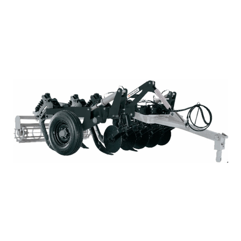
Baldan GTCR User manual

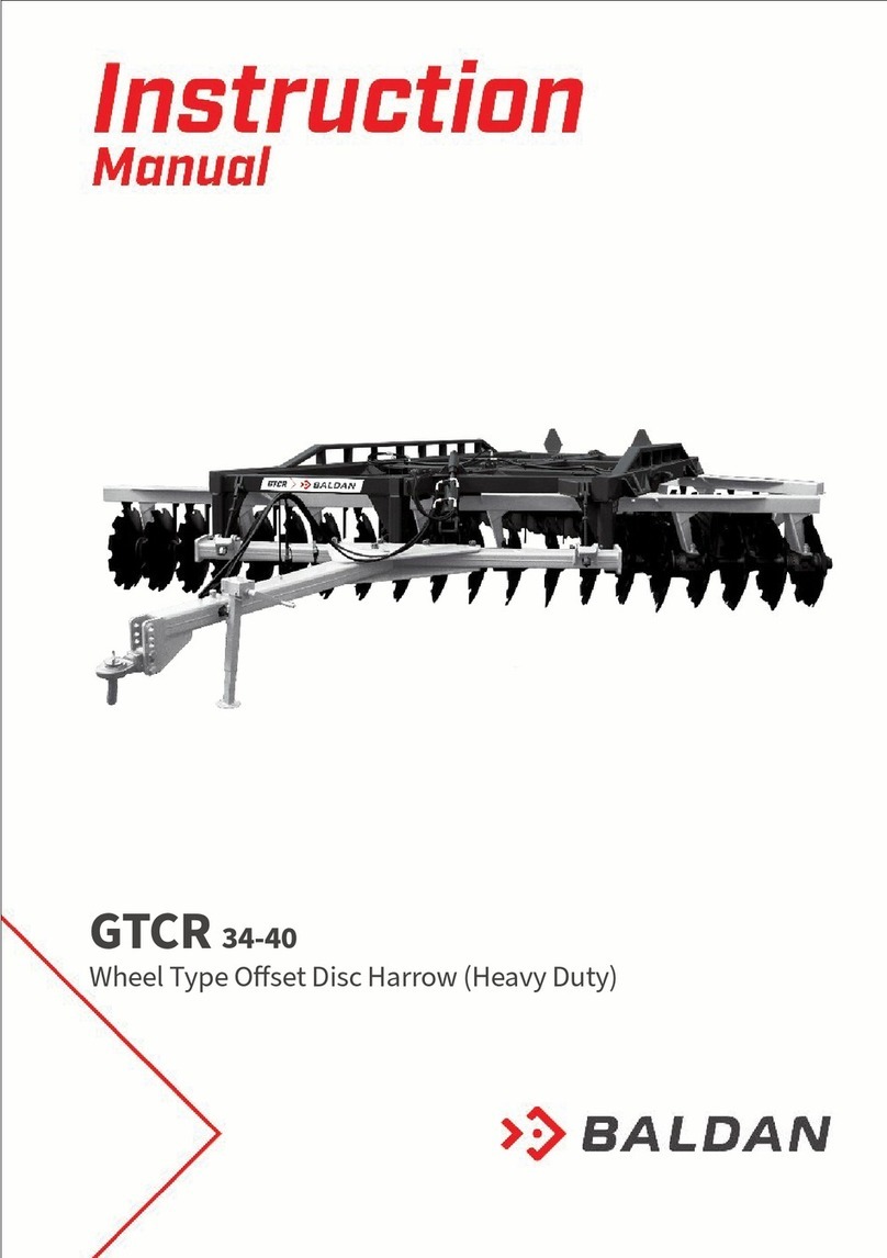
Wheel Type Oset Disc Harrow
Remote Control - Heavy Duty
GTCR
Wheel Type Oset Disc Harrow
Remote Control - Heavy Duty
GTCR-CR


We thank you for the preference and congratulate your excellent choice in acquiring an
implement of outstanding quality, manufactured in accordance with the advanced
technology of BALDAN IMPLEMENTOS AGRÍCOLAS S/A.
This manual will assist you, in proceeds necessaries, since when you bought until the
operational proceeds application, security and maintenance.
The BALDAN guarantees that deliver this implement to the dealer, working properly, and in perfect
conditions.
The dealers it’s under the responsibility to keep the protection and conservation while keep the implement in your stock, and
than, to assembly, tighten, lubrication and overhaul.
On time of the technical deliver, the dealer must to have conducted the user customer about the manutentation, safety, and
your obligations in a possible technical assistance, the obligation to see the warranty terms and read the instruction manual.
Any solicitation of warranty, please contact our Baldan technical service, by your Baldan dealer that you bought our implement.
Rearm the necessity to read carefully of warranty certicate and note all of items from this manual, therefore you will increase
the working life of your equipment.
INTRODUCTION

Wheel Type Oset Disc Harrow
Remote Control - Heavy Duty
GTCR
Wheel Type Oset Disc Harrow
Remote Control - Heavy Duty
GTCR-CR

INDEX
01 - SAFETY RULES ............................................................................................................................................................................................................. 4
02 - COMPONENTS ............................................................................................................................................................................................................. 9
03 - TECHNICAL SPECIFICATIONS GTCR / GTCR-CR ...................................................................................................................................................... 11
04 -
MOUNTING.................................................................................................................................................................................................................... 12
Assemble of front and rear gang..................................................................................................................................................................................................................... 14
Mounting of the wheel assembly of a single wheel gtcr/gtcr-cr model with 10 disc blades and the hydraulics that command the system....................................................... 16
Mounting the wheel assembly of the dual wheel model harrows gtcr 12 - 14 ano 16 disc blades and the hydraullcs
that command the system .............................................................. 17
Mounting of the wheel assembly of the heavier dual wheel model harrows gtcr / gtcr-cr 18 - 20 - 22 - 24 and gtcr 30 and the hydraulics that command the system............. 18
Assembllng of the hitch system....................................................................................................................................................................................................................... 19
05 - HITCHING THE HARROW ONTO THE TRACTOR (GTCR / GTCR-CR)...................................................................................................................... 20
06 - ADJUSTMENTS ANO OPERATION............................................................................................................................................................................. 21
Adjustment of the opening of the harrow ....................................................................................................................................................................................................... 21
Displacement of the harrow unit..................................................................................................................................................................................................................... 21
Adjustment of the transversal bar................................................................................................................................................................................................................... 22
07 - OPERATION PATIERNS ................................................................................................................................................................................................ 23
08 – CLEANING.................................................................................................................................................................................................................... 24
09 - LUBRICATION ............................................................................................................................................................................................................... 25
Equivalent gaease table.................................................................................................................................................................................................................................. 25
10 - LUBRICATION POINTS................................................................................................................................................................................................. 26
11 - APPROXIMATE HOURLY PRODUCTION ................................................................................................................................................................... 28
12 - IDENTIFICATION .......................................................................................................................................................................................................... 30

Instruction Manual
GTCR/GTCR-CR 4 5 GTCR/GTCR-CR
01 SAFETY RULES
THE SAFETY ALERT SYMBOL IDENTIFES IMPORTANT MESSAGE ON THE MESSAGE ON THE ENGINE, WHEN YOU SEE THIS SYMBOL, BE ALERT TO THE
POSSIBILITY OF DEATH OR PERSONAL INJURY. FALLOW THE INSTRUCTIONS IN THE SAFETY MESSAGE.
WARNING WARNING WARNING WARNING
• Read this instruction manual ca-
refully to know the recommen-
ded safety rules.
• Only start the tractor opera-
tions, when are you properly ac-
commodated and with the seat
belt fasted.
• Never carry people over the tractor
or equipment.
• There are risks of serious injury by
tipping when working on slopes.
• Never use excessive speed.

Instruction Manual
5 GTCR/GTCR-CR
01 SAFETY RULES
THE SAFETY ALERT SYMBOL IDENTIFES IMPORTANT MESSAGE ON THE MESSAGE ON THE ENGINE, WHEN YOU SEE THIS SYMBOL, BE ALERT TO THE
POSSIBILITY OF DEATH OR PERSONAL INJURY. FALLOW THE INSTRUCTIONS IN THE SAFETY MESSAGE.
WARNING WARNING WARNING
• Do not work with the tractor
if the front bee without enough
weight to the rear equipment.
There is tendency to lift , add
weights at front or front wheels.
• Before any equipment main-
tenance, make sure that is pro-
perly stopped
• Avoid getting hit
• Never weld the wheel mounted with tire,
the heat may cause air pressure increase
and provoke the explosion of the tire.
• When lling the tire, stand at the side of
the tire, never in froint of it.
• When lling the tire, always use a contain-
ment device (lling cage).
WARNING
• Do not perform adjustments
while GTCR/GTCR-CR is running.
• When performing any servi-
ce on GTCR/GTCR-CR, switch o
the tractor rst. Use appropria-
te tools.

Instruction Manual
GTCR/GTCR-CR 6 7 GTCR/GTCR-CR
ALCOHOLIC BEVERAGE OR SOME MEDICATIONS MAY CAUSE LOSS OF REFLEXES AND CHANGE THE OPERATOR´S PHYSICAL CONDITIONS. FOR
THIS REASON, NEVER OPERATE THIS EQUIPMENT UNDER ANY OF THESE SUBSTANCES.
01 SAFETY RULES
WARNING WARNING
• The hydraulic oil operates pressurized and can cause serious injuries, in case of
leakage. Periodically verify the condition of the hoses. If there are any signs of
leakage, replace them immediately.
• Before connecting or disconnecting hydraulic hoses, release the pressure from
the system, activating the control when the tractor is turned o.
• Dispose residues inappropriately
aects the environment and the ecolo-
gy since you will be polluting rivers, ca-
nals or the soil.
• Inform yourself about the proper way
of recycling or disposing residues.
PROTECT THE ENVIRONMENT!
WARNING
• Keep away from the active seeder ele-
ments (discs), they are sharp and can
cause accidents.
• Whenever performing any work on the
discs, wear safety gloves on your hands.

Instruction Manual
7 GTCR/GTCR-CR
The incorrect handling of this equipment can result in serious or fatal accidents. Before using the implement, read carefully the instruc-
tions of this manual. Be sure that the person responsible for the operation is instructed about the correct handling, safety and if read and
understood the instructions manual concerning this machine.
WARNING
01 - When operate with the implement, do not allow people to stay close or above the implement. (The platforms are used to supply the stores
and not to transport people).
02 - During assembly or desassembly the discs section use proctection gloves.
03 - When turn on or o the hydraulic rubbers, alleviate the circuit pressure.
04 - Check periodically the rubbers conservation. If there is indicium of oil emptying change it immediatelly because the oil works under high
pressure and may cause serious damages.
05 - Do not use much large clothes because they can fasten the implement.
06 - Putting in action the tractor, be correctly placed at the operator seat and aware about the correct and safety handling both tractor and
implement. Place always the gearshift crank at the neutral position, turn o the gear of the power command and place the hydraulic commands at
the neutral position.
07 - Do not turn on the tractor in a closed place, without appropriate ventilation because the gas are bad for health.

Instruction Manual
GTCR/GTCR-CR 8 9 GTCR/GTCR-CR
08 - While maneuver the tractor to clamp the implement be sure if there is space enough and nobody is too much close, maneuver always in slow
gear and be ready to brake in case of emergency.
09 - Do not adjust the implement working.
10 - Working in inclined soil try to keep the necessary stability. In case of instability reduce the acceleration, turn the wheels to the inclined side
of the soil and never lift the implement.
11 - Conduct the tractor always in safety speeds, specially working in irregular or inclined soil, keep the tractor always geared.
12 - In case of conducting the tractor on road, keep the brake pedal connected.
13 - Do not work with the front of the tractor light. If there is trend to lift up add more weight in front or at the front wheels.
14 - Getting out the tractor place the gearshift at the neutral position and apply the park brake. Do never let clamped implements at the tractor
with the hydraulic system at the lifted position.
15 - Drugs and alcohol will aect an operator’s alertness and coordination. Do not operate any engine under these conditions.
16 - Explain the operation, inspect and maintenance instructions to those users or operators who can not read.

Instruction Manual
9 GTCR/GTCR-CR
Figure 1
02 COMPONENTS
GTCR WHEEL TYPE OFFSET DISC HARROW REMOTE CONTROL HEAVY DUTY
01 - Main front frame
02 - Main rear frame
03 - Main chassis
04 - Stabllizer bar
05 - Hydraulic piston
06 - Hydraulic hoses
07 - Wheel axles
08 - Wheel articulatiion
09 - Wheels
10 - Disc blades
11 - Stabilizer rod
12 - Stabilizer bar support
13 - Transversal bar
14 - Hitch beam
15 - Hitch shackel
16 - Hydraulic hose support 15
14
13
10
9
8
5
7
4
16
6
12
11
3
2
1

Instruction Manual
GTCR/GTCR-CR 10 11 GTCR/GTCR-CR
Figure 2
GTCRCR WHEEL TYPE OFFSET DISC HARROW REMOTE CONTROL HEAVY DUTY
15
14
13
10
9
8
5
7
4
16
6
12
11
3
2
1
01 - Main front frame
02 - Main rear frame
03 - Main chassis
04 - Stabllizer bar
05 - Hydraulic piston
06 - Hydraulic hoses
07 - Wheel axles
08 - Wheel articulatiion
09 - Wheels
10 - Disc blades
11 - Stabilizer rod
12 - Stabilizer bar support
13 - Transversal bar
14 - Hitch beam
15 - Hitch shackel
16 - Hydraulic hose support

Instruction Manual
11 GTCR/GTCR-CR
Table 1
03 TECHNICAL SPECIFICATIONS GTCR / GTCRCR
•Optional: Single tyre 7.50 x 16 for models GTCR 10 blades. / Single 7.50 x 16 for models GTCR 12 blades optional double tyre 7.50 x16. / Double tyre 7.50 x 16 for models
GTCR from 14 to 30 blades. / Single tyre 900 x 20 and 400 x 60 for models GTCR from 18 to 30 blades. / Tyre 11L - 15 for models GTCR 16 blades
Model Nr of discs Disc spacing (mm) Disc diameter
(ø)
Spherical disc
blade (mm)
Axle diameter
(ø)
Working width
(mm)
Working deph
(mm)
Approx. Weidht (Kg) Required tractor
power (HP) Ground wheel
30” 32”
GTCR 10 340 30”- 32” 9,0 e 12,0 2.1/4” 1530 200 - 300 1875 1977 90 - 110 Simples
GTCR 12 340 30”- 32” 9,0 e 12,0 2.1/4” 1870 200 - 300 2493 2619 118 - 125 Simples
GTCR 14 340 30”- 32” 9,0 e 12,0 2.1/4” 2390 200 - 300 2632 2821 140 - 150 Duplo
GTCR 16 340 30”- 32” 9,0 e 12,0 2.1/4” 2550 200 - 300 2886 3080 155 - 168 Duplo
GTCR 18 340 30”- 32” 9,0 e 12,0 2.1/4” 2890 200 - 300 3542 3742 175 - 190 Duplo
GTCR 20 340 30”- 32” 9,0 e 12,0 2.1/4” 3230 200 - 300 3833 4053 200 - 210 Duplo
GTCR 22 340 30”- 32” 9,0 e 12,0 2.1/4” 3570 200 - 300 4107 4369 222 - 230 Duplo
GTCR 24 340 30”- 32” 9,0 e 12,0 2.1/4” 3910 200 - 300 4357 4661 240 - 250 Duplo
GTCR 30 340 30”- 32” 9,0 e 12,0 2.1/4” 4930 200 - 300 4798 5112 300 - 320 Duplo
Model Nr of discs Disc spacing (mm) Disc diameter
(ø)
Spherical disc
blade (mm)
Axle diameter
(ø)
Working width
(mm)
Working deph
(mm) Approx. Weidht (Kg) Required tractor
power (HP) Ground wheel
GTCR-CR 18 360 32” 9,0 e 12,0 2.1/4” 3060 200 - 300 3980 175 - 190 400 x 60
GTCR-CR 20 360 32” 9,0 e 12,0 2.1/4” 3420 200 - 300 4180 200 - 210 400 x 60
GTCR-CR 22 360 32” 9,0 e 12,0 2.1/4” 3780 200 - 300 4390 222 - 230 400 x 60
GTCR-CR 24 360 32” 9,0 e 12,0 2.1/4” 4140 200 - 300 4630 240 - 250 400 x 60
Table 2
Baldan reserves the right to change the technical features of this product without prior warning.
The technical specications are approximate and informed in the normal working conditions.

Instruction Manual
GTCR/GTCR-CR 12 13 GTCR/GTCR-CR
04
MOUNTING
1 - Before you start... Check if you receive the product without any violation
of the packing. In case the cargo has signs of violation, call the insurance
agent to witness the fact and assist further unpacking of the cargo for mis-
sing items.
2 - Prepare the unloading area for a clean, safe and organized operation and
do not allow the people to work without safety material such as gloves.
3 - Assembling normally starts with the disc gangs .The gang components
leave the factory pre-mounted without the disc blades.
Carefully dismount the gang , leaving the parts precisely in the same se-
quence order, withouit turning the separatar spools and bearing housings
around, because the extremeties of those have a concave face on one and
a convex face on the other and this is not so easy to see, if you don’t pay at-
tention to it . These faces match with the convex and concave disc surfaces
for a tight t.
4 - Fig (3) shows the mounting sequence of the axle assemblies.
5 - The bearings housings have either a grease nipple or an oil ll plug.
Mounted correctly on lhe harrow, these components should be in the op-
posite of the drive direction.
1
3
10
7
2
4
5
3
45
7
6
7
7
8
9
87
7
6
Figure 3

Instruction Manual
13 GTCR/GTCR-CR
gTCr 10 DisCs
gTCr / gTCr-Cr 20 DisCs gTCr / gTCr-Cr 22 DisCss gTCr / gTCr-Cr 24 DisCs gTCr 30 DisCs
gTCr 12 DisCs gTCr 14 DisCs gTCr 16 DisCs gTCr-Cr 16 DisCs gTCr / gTCr-Cr 18 DisCs
Figures 4
= beariNg HOuse
= sPaCer sPOOl
= DisC blaDe
legeND
- Figure (4) shows the assembling 01 the disc gang sections for each model of the harrow.

Instruction Manual
GTCR/GTCR-CR 14 15 GTCR/GTCR-CR
ASSEMBLE OF FRONT AND REAR GANG
Figure 5
1
2
3
4
Insert the front gang (1 gure 05) and rear (2), in safety terrain.
Install the frame (3) over the gangs and attach using the bolts (4).

Instruction Manual
15 GTCR/GTCR-CR
Figure 6 Figure 7
Figure 8
1
2
1
10mm
Raise the gang front or rear install the blades
as illustrated on the drawing 04, checking
the bearing and gang holes are aligned, then
mount using the bolt (#1 - Drawing 05), be
sure the that the support is turned in a conca-
ve direction as illustrated on the drawing 06.
Raise the second gang, install the blades as
instructed in the point above beteween the
disc concave face the oposite direction to the
rst gang.
Also put the wipers central gure 2 item 08,
the front and rear frames.

Instruction Manual
GTCR/GTCR-CR 16 17 GTCR/GTCR-CR
- Slide the pillow block hubs (2) onto the articulation axles of the whe-
els (3) and fasten them with the bolts (4), onto the main chassis (1) Now
introduce the pre-mounted wheel (5), on the articulation axle (3), pla-
ce the strut washer, nut (6) and lock the unit, using the appropriate litt-
le screw bolt (7).
- Place the hydraulic articulation piston (8) lock the unit using pins
(9) and connect the hydraulic hoses (10).
- Connect the stabilizer bar (11) on the articulation system locking
the 5ame with pin (12).
MOUNTING OF THE WHEEL ASSEMBLY OF A SINGLE WHEEL GTCR/GTCRCR MODEL WITH 10 DISC BLADES ANDTHE HYDRAULICS THAT COMMAND THE SYSTEM
Figure 9
19
4
2
56
11
7
9
8
10

Instruction Manual
17 GTCR/GTCR-CR
Attach the hubs (2) onto the articulationn axle (3) and fasten them
onto the main frame (1) with bolts. Place de axle articulation sup-
port (4) on the articulation axle (3) and lock il with pins (5). Place the
support plate (6) on the coupler of the main frame and lock with
pin (7) and on the axle support with pin (8).
- Place the pre-mounted wheel assembly (9) onto the support of
the articulation axle and fasten with screw bolts (10).
- Place the hydraulic articulation piston (13) and lock it with pins
(14) Connect the hydraulic hoses (15) to the piston and fasten the
hoses onto the main chassis (1) with the fasteners (16) as shown
in the illustration .
- Connect the stabilizer bar (17) onto the articulations axles and
lock it with pin (18).
MOUNTING THE WHEEL ASSEMBLY OFTHE DUAL WHEEL MODEL HARROWS GTCR 12
14 AND 16 DISC BLADES AND THE HYDRAULLCS
THAT COMMANDTHE SYSTEM
Figure 10
12
10
15
9
17
1
7
1314
6
8
18
4
5
3
2
16
11

Instruction Manual
GTCR/GTCR-CR 18 19 GTCR/GTCR-CR
- Attach the hubs (2) onto the articulation axle (3) and fasten them onto the
main frame (1) with the bolts. Place the axle articulation support (4) onta the
axle (3) using the pins (5) and lock it with the screw bolt. Fix the plates (6)
of the axle support (4) onto the main chassis (1) with pin (7) locking it with
screw bolts (10).
- Faslen lhe wheels (11) onlo the axle (9) wilh bolls (12).
-Place the hydraulic articulation pistons (13) with the base of the cylinder -
xed onto the main frame (1) using pin (14) and the other end of the cylinder
unit xed onto the articulation axle with pin (15).
Fasten de hydraulic oil distributor (16) onto the main frame (1)
Connect the hydraulic hoses (17) of the piston to the distributor
Connect the hose (18) to the distributor and x them onto the
main chassis with the fasteners (19) supplied, as illustrated.
Connect the stabilizer bar (20) onto the articulation axle (3) with
pin (21).
Figure 11
2
11
10
9
20
18
19
7
6
15
13
14
16
17
4
5
8
3
2
121
MOUNTING OF THE WHEEL ASSEMBLY OFTHE HEAVIER DUAL
WHEEL MODEL HARROWS GTCR / GTCRCR 18 20 22 24 AND
GTCR 30 AND THE HYDRAULICS THAT COMMAND THE SYSTEM.
This manual suits for next models
1
Table of contents
Other Baldan Farm Equipment manuals

Baldan
Baldan CRSG 32 User manual

Baldan
Baldan CRSG 32 User manual

Baldan
Baldan CRI-E User manual

Baldan
Baldan ASDA User manual

Baldan
Baldan MOVERE User manual

Baldan
Baldan CRSG 12 User manual

Baldan
Baldan PNA 3000 User manual

Baldan
Baldan CRI User manual

Baldan
Baldan CRI-A User manual

Baldan
Baldan SPDE CXP User manual