5.5 Maintenance
Warning: Do not disassemble or try to repair the device. In case of any
malfunction or fault, replace the entire device.
Warning: Correct operation cannot be guaranteed when the device is
deformed or damaged.
The installer is responsible for establishing the sequence of functional tests to which
the installed device is to be subject for complete maintenance.
The testing sequence can vary according to machine complexity and circuit diagram,
therefore the functional test sequence detailed below is to be considered as minimal
and not exhaustive.
At least once a year or after prolonged stoppage, carry out the following checking
operations.
1) Lock the protection and start the machine. It must be impossible for the protection
to be opened.
2) With the machine stationary and the protection open, the machine must not be
allowed to start.
3) When the anti-panic release button (if fi tted) is pressed, the protection must open
freely and the machine must not start. Each time the release button is activated, the
machine must stop and the door must open immediately. The release button must
slide freely, without sticking, and be tightly screwed in. The signs placed inside the
machine, indicating the function of the release button (if fi tted), must be intact, clean
and clearly readable.
4) With the protection closed but not locked, the machine must not be allowed to start
(not applicable to safety output activation mode 2, see par. 3.3).
5) All external parts must be undamaged.
6) If the device is damaged, replace it completely.
7) The actuator must be securely locked to the door, make sure that none of the
machine operator’s tools can be used to disconnect the actuator from the door.
8) The device has been created for applications in dangerous environment, therefore
its operation is limited over time. 20 years after its production date, the device must
be totally replaced, even when still working. The production date is found next to the
product code (See paragraph 5.10 – MARKING)
5.6 Precautions during wiring
• Check that the power supply is correct before supplying the device with power.
• Keep the charge within the values specifi ed in the electrical operation categories.
• Disconnect the power supply before accessing the device connections.
• Only connect and disconnect the device when the power is off.
• Do not open the internal device cover under any circumstances.
• Discharge static electricity before handling the product, by making contact with a
metal mass connected to earth. Any strong ESD could damage the device.
• Power the safety switch and other connected devices from one single SELV-type
source and in conformity with the relevant standards.
• Always connect the protection fuse (or equivalent device) in series with the power
supply for each device (See paragraph 6.3 – ELECTRICAL DATA).
• The device contains two PUSH-IN spring-operated terminal boards for connecting
the following electrical leads:
Cross section of solid leads or leads with tips min. 0.34 mm2 (AWG 22) max. 1.5 mm2
(AWG 16).
Cross section of leads with pre-insulated tips min. 0.34 mm2 (AWG 22) max. 0.75 mm2
(AWG 18).
Stripping length of electrical leads: min. 8 mm - max. 12 mm
5.7 Additional prescriptions for safety applications with personal protection
functions
Provided that all previous requisites are fulfi lled, when the devices installed are
intended to ensure personal protection, the following additional prescriptions are also
to be observed:
• In all cases, device operation implies the knowledge and observance of the following
standards: EN 60947-5-3, EN ISO 13849-1, EN 62061, EN 60204-1, EN ISO 14119,
EN ISO 12100.
• Correct operation of safety devices must be checked periodically, at intervals
established by the machine manufacturer according to the machine danger level,
and in any case must be checked at least once a year.
5.8 Limitations of use
• The device can be used as a component within a system having safety category 4 /
PL e according to EN ISO 13849-1 standard and integrity level SIL CL 3 according
to EN 62061 standard.
• Use the device by following the instructions, keeping to its operating limits and
respecting the current safety standards.
• The devices have specifi c application limitations (minimum and maximum ambient
temperature, mechanical working life, protection degree etc.). These limitations are
met by the device only if considered individually and not as combined with others.
• The manufacturer’s liability is to be excluded in the following cases:
• Use not conforming to the intended purpose.
• Failure to observe safety instructions.
• Fitting operations not carried out by qualifi ed and authorized personnel.
• Omission of functional tests.
• For the cases listed below, contact our assistance service (See paragraph
SUPPORT):
• Nuclear power stations, trains, airplanes, motorcars, incinerators, medical
appliances or any other applications where the safety of two or more persons
depends on correct device operation.
• Cases not mentioned on the instruction sheet.
5.9 Functional tests before commissioning the device
The device installer is responsible for establishing the sequence of functional tests to
which the installed device is to be subject before machine commissioning. The testing
sequence can vary according to machine complexity and circuit diagram, therefore
the functional test sequence detailed below is to be considered as minimal and not
exhaustive.
1) Lock the protection and start the machine. It must be impossible for the protection
to be opened.
2) With the machine stationary and the protection open, the machine must not be
allowed to start.
3) When the escape release button (if fi tted) is pressed, the protection must open
freely and the machine must not start.
4) When the auxiliary release (if fi tted) is activated, the protection must open freely and
the machine must not start.
5) With the protection closed but not locked, the machine must not be allowed to start
(not applicable to safety output activation mode 2, see par. 3.3).
6) The actuator must be securely locked to the door; make sure that none of the
machine operator’s tools can be used to disconnect the actuator from the door.
5.10 Marking
The outside of the device is provided with external marking positioned in a visible
place.
Marking includes:
• Producer trademark
• Product code • Batch number and production date. Example: A14 NG1-411. The
fi rst character of the batch indicates the production month (A=January, B=February
etc…). The second and third characters indicate the production year (14 =2014,
15=2015 etc…).
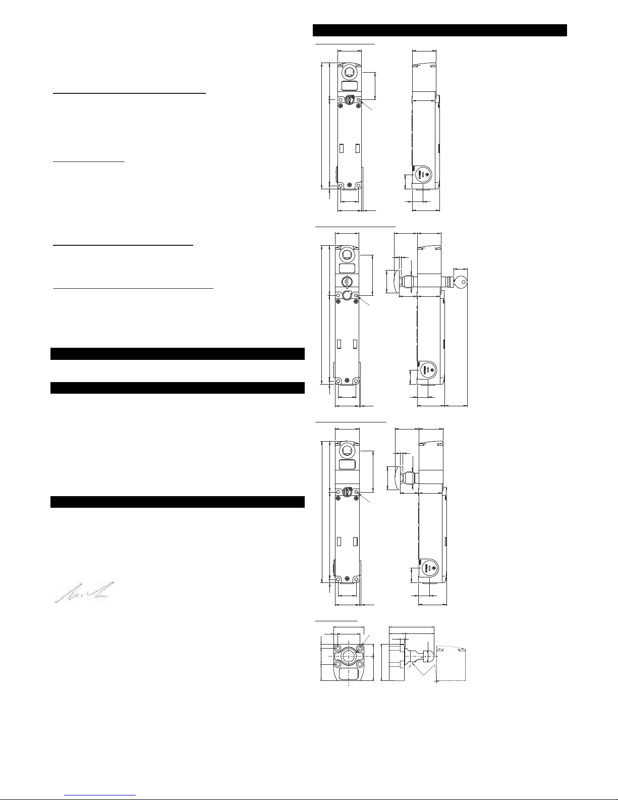
6 TECHNICAL DATA
6.1 Housing
Metal housing, with powder coating.
Three M20x1.5 threaded cable inlets
Protection degree: IP67 according to EN 60529
IP69K according to ISO 20653
with cable gland (or other equivalent connection system) having equal or higher protection degree
6.2 General data
SIL (SIL CL) level: up to SIL 3 according to EN 62061
Performance Level (PL): up to PL e according to EN ISO 13849-1
Safety category: up to 4 according to EN ISO 13849-1
Interlocking with lock, with non-contact, coded: type 4 according to
EN ISO 14119
Coding level according to EN ISO 14119: low level with SCA actuator
high level with UCA actuator
PFHd: 8.07 E-10
MTTFd (single channel): 1883 years
DC: High
Mission time: 20 years
Ambient temperature: from -20°C to +50°C
Storing temperature: from -40°C to +75°C
Maximum operation altitude: 2000 m
Time for starting the switching operation: 2 s
Maximum activation frequency with
actuator lock and release: 600 operation cycles*/hour
Mechanical life: 1 million operation cycles*
Maximum activation speed: 0.5 m/s
Minimum activation speed: 1 mm/s
Fitting position: any
Maximum force before breakage F1max: 9750 N according to ISO 14119
Maximum holding force FZh: 7500 N according to ISO 14119
Clearance of locked actuator: 4 mm
Extraction force of released actuator: 30 N
*(One cycle of operations is equivalent to two operations, one for closing and one for opening as
prescribed by the EN 60947-5-1 standard)
6.3 Electrical data
Rated operation voltage Ue: 24 Vdc ±10% SELV
Operation current at Ue voltage:
- minimum: 40 mA
- with electromagnet activated: 0.4 A
- with electromagnet activated and all outputs at maximum power: 1.2 A
Rated insulation voltage Ui: 32 Vdc
Thermal current Ith: 0.25 A
Rated impulse withstand voltage Uimp: 1.5 kV
External protection fuse: 1.5 A type F
Overvoltage category: III
Electrical life: 1 million operation cycles
Solenoid insertion ratio: 100% ED
Electromagnet consumption: 9 W
Pollution degree: 3 according to EN 60947-1
6.3.1 Electrical data for IS1/IS2/I3/I4/I5/EDM inputs
Rated operation voltage Ue: 24 Vdc
Rated absorbed current: 5 mA
6.3.2 Electrical data for OS1/OS2 safe outputs
Rated operation voltage Ue: 24 Vdc
Type of output: PNP type OSSD
Maximum current per output Ie: 0.25 A
Minimum current per output Ie: 0.5 mA
Category of use: DC13; Ue=24 Vdc, Ie=0.25 A
Short-circuit detection: Yes
Protection against overcurrent: Yes
Internal self-resetting protection fuse: 1.1 A
Electrical life: 1 million operation cycles
Time for deactivation impulses on safe outputs: <300 μs
Capacity admitted between output and output: <200 nF
Capacity admitted between output and earth: <200 nF
Length of connection cable, max. 50 m
Cable lengths and cross sections infl uence pulses to the safety outputs. The capacity
of the connection cables may not exceed the values listed above.