6
6 INSTRUCTIONS FOR PROPER USE
6.1 Installation
Attention: The installation must exclusively be carried out by qualified personnel.
The OS1 and OS2 safety outputs of the device must be connected to the safety circuit
of the machine. The O3 and O4 signal outputs are not safety outputs and cannot be
used individually in a safety circuit to determine the "protection closed" state.
- Do not stress the device with bending and torsion.
- Do not modify the device for any reason whatsoever.
- Do not exceed the tightening torques specified in the present operating
instructions.
- The device carries out a personnel protection function. Any inadequate installa-
tion or tampering can cause people serious injuries and even death as well as
property damage and financial losses.
- These devices must not be bypassed, removed, turned or disabled in any other
way.
- If the machine where the device is installed is used for a purpose other than the
intended use, the device may not provide efficient personnel protection.
- The safety category of the system (according to EN ISO 13849-1), including
the safety device, also depends on the external devices connected to it and
their type.
- Before installation, make sure the device is not damaged in any part.
- Before installation, ensure that the connection cables are not powered.
- Avoid excessive bending of connection cables in order to prevent any short cir-
cuits or power failures.
- Do not paint or varnish the device.
- Do not drill the device.
- Do not use the device as a support or rest for other structures, such as cable
ducts or sliding guides.
- Before commissioning, make sure that the entire machine (or system) complies
with all applicable standards and EMC directive requirements.
- The device fitting surface must always be smooth and clean.
- Should the installer be unable to fully understand the documents, the product
must not be installed and the necessary assistance may be requested from the
manufacturer (see section SUPPORT).
- Check for correct switching of the outputs and correct operation of the system
comprising the device and associated safety module before commissioning the
machine and in regular intervals.
- In proximity of the device do not carry out arc welding, plasma welding, or any
other process that may generate electromagnetic fields of intensity higher than
the limits prescribed by the standards, even when the device is off. Where weld-
ing operations are to be carried out in the proximity of the previously installed
device, it must first be moved away from the work area.
- When the device is installed on a mobile door frame and the actuator is installed
on a mobile door, check that the device isn't damaged by simultaneous opening
of the frame and the door.
- After installation, check for correct operation of the auxiliary release (if present)
and the escape release button.
- Always attach these operating instructions to the manual of the machine in which
the device is installed.
- These operating instructions must be kept available for consultation at any time
and for the whole period of use of the device.
6.2 Not to be used in the following areas
- An environment where continuous temperature changes cause condensation
inside the device.
- An environment where the application causes the device to be subject to strong
impact or vibration.
- An environment where explosive or flammable gases are present.
- An environment where the device may become coated with ice.
- An environment containing strongly aggressive chemicals, where the products
coming into contact with the device may impair its physical or functional integrity.
6.3 Mechanical limit stop
Attention: The door must always be provided with an independent mechanical
limit stop at the end position.
Do not use the device as mechanical limit stop for the door.
6.4 Maintenance and function tests
Attention: Do not disassemble or try to repair the device. In case of any malfunc-
tion or fault, replace the entire device.
Attention: In case of any damage or wear, the entire device with actuator must
be replaced. Correct operation cannot be guaranteed when the device is deformed
or damaged.
- The device installer is responsible for establishing the sequence of function tests
to which the installed device is to be subjected to before machine commissioning
and during maintenance intervals.
- The testing sequence can vary according to machine complexity and circuit
diagram, therefore the functional test sequence detailed below is to be consid-
ered as minimal and not exhaustive.
- Perform the following sequence of checks before the machine is commissioned
and at least once a year (or after a prolonged shutdown):
1. Lock the protective device and start the machine. It must be impossible for the
protective device to be opened.
2. Try to start the machine while the protective device is open. The machine must
not start.
3. Check correct actuator to device alignment. If the actuator insertion opening is
worn, replace the entire device and actuator assembly.
4. When the escape release button (if present) is pressed, the protective device must
open freely and the machine must not start. Each time the escape release button
is activated, the machine must stop and the safety door must open immediately.
The escape release button must slide freely and be tightly screwed in. The signs
placed inside the machine, indicating the function of the escape release button (if
fitted), must be intact, clean and clearly readable.
5. When the auxiliary release (if present) is activated, the protective device must
open freely and the machine must not start (for devices with mode 3, check that
the machine shows the expected behavior)
6. If the protective device is closed but not locked, it must not be possible for the
machine to start (not applicable in mode 2, for devices with mode 3, check that the
machine shows the expected behavior).
7. All external parts must be undamaged.
8. If the device is damaged, replace it completely.
9. The actuator must be securely locked to the safety door. Check that none of the
operating personnel's tools can be used to disconnect the actuator from the door.
10. The device has been created for applications in dangerous environment, therefore
its mission time is limited. 20 years after its production date, the device must be
totally replaced, even when still working. The production date is placed next to the
part number (see section MARKINGS).
6.5 Wiring
Attention: Check that the supply voltage is correct before powering the device.
- Keep the loading within the reference values of the respective electrical usage
categories.
- Only connect and disconnect the device when the power is off.
- Discharge static electricity before handling the product, by making contact with
a metal mass connected to earth. Any strong ESD could damage the device.
- Power the safety device and other connected components from one single
SELV-type source and in conformity with the relevant standards.
- Always connect the protection fuse (or equivalent device) in series with the
power supply for each device.
- During and after mounting, do not pull the electrical cables connected to the
device.
- At the end of the wiring, check that no contaminating element has been intro-
duced inside the device.
- Before closing the housing cover verify the correct positioning of the gaskets.
- Verify that the cables, wire-end sleeves, cable numbering systems and any other
parts do not obstruct the cover from closing correctly or if pressed between them
do not damage or compress internal parts.
- During and after mounting, do not pull the electrical cables connected to the
device. If traction is applied to the cables (not supported by an appropriate cable
gland), internal parts of the device may be damaged.
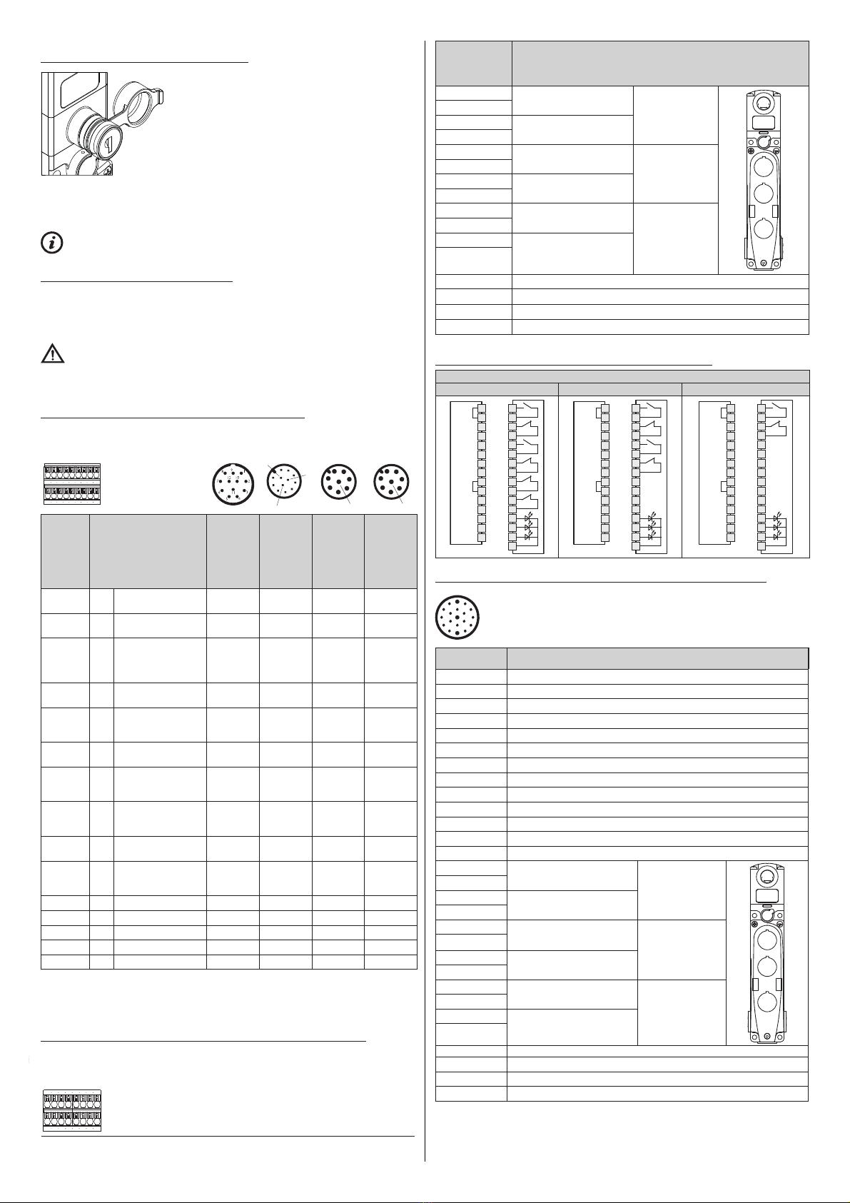
- The device contains two PUSH-IN spring-operated terminal strips for connecting
the following electrical leads.
The cross section of wires or leads with wire-end sleeves:
at least 0.34 mm2(AWG 22) and no more than 1.5 mm2(AWG 16).
The cross section of leads with welded-on wire-end sleeves:
at least 0.34 mm2(AWG 22) and no more than 0.75 mm2(AWG 18).
Stripping length of electrical leads: min. 8 mm - max. 12 mm.
6.6 Additional prescriptions for safety applications with personal protection
functions
Provided that all previous prerequisites are fulfilled, and the devices installed are
intended to ensure personnel protection, the following additional regulations are also
to be observed.
Device operation implies the knowledge and observation of the following stan-
dards: EN 60947-5-3, EN ISO 13849-1, EN 62061, EN 60204-1, EN ISO 14119,
EN ISO 12100.
6.7 Limitations of use
- By connecting the two electromagnet activation inputs IE1, IE2 on two distinct
channels to two OSSD safety outputs of a safety PLC or safety module, the
device can be used as a component with interlocking functions in a safety sys-
tem with safety category 4 /PL e according to EN ISO 13849-1 and safety integ-
rity level SIL CL 3 according to EN 62061.
- By connecting both electromagnet activation inputs IE1 and IE2 to the same
channel, or by connecting the I4 input only after having short-circuited the two
electromagnet activation inputs IE1 and IE2, the device can be used as a com-
ponent with locking functions in a safety system with safety category 2 / PL d
according to EN ISO 13849-1 and safety integrity level SIL CL 2 according to
EN 62061. Any fault on the single I4 activation line of the electromagnets can
cause the actuator to be released, and the safety outputs switched off.
- Use the device following the operating instructions, complying with its operation