Multi-Phase Surge Protective Devices with Integral
Disconnect Switch
Cat. Nos. 52120-7MS, 52277-7MS, 52120-7CS, 52277-7CS
For main distribution and branch circuit panels
WARNINGS AND CAUTIONS:
• TO AVOID FIRE, SHOCK, OR DEATH: TURN OFF POWER AT CIRCUIT BREAKER OR FUSE AND TEST THAT
THE POWER IS OFF BEFORE WIRING!
• IT IS RECOMMENDED THAT THE 52000 SPD PANEL PROTECTION SYSTEM BE INSTALLED BY
AN ELECTRICIAN.
WARNINGS AND CAUTIONS:
• TO BE INSTALLED AND/OR USED IN ACCORDANCE WITH APPROPRIATE ELECTRICAL CODES AND
REGULATIONS (INCLUDING NEC/CEC, AS APPLICABLE).
• USE THIS DEVICE WITH COPPER OR COPPER CLAD WIRE ONLY.
• OPERATE INDOORS BETWEEN 30-90% RELATIVE HUMIDITY.
INSTALLATION ENGLISH
PK-93014-10-00-0A
DESCRIPTION
FEATURES
TO INSTALL
The 52000 SPD Panel Protection System with Integral Disconnect Switch is a
high-performance Surge Protective Device designed for use on main distribution
and branch circuit panels.
• cULus Listed.
• Integral disconnect switch with lockout feature.
• Replaceable plug-in modules, which facilitate maintenance.
• Hybrid component suppression design.
• 7 Mode Protection.
• Diagnostic monitoring of each phase module.
• Audible and visual failure indicators.
• Provisions for operation with an optional Remote Supervisor Panel, allowing monitoring of
SPD status from distant locations.
• 50-60 Hz operation.
• ANSI/IEEE Location Category A, B & C.
• Optional surge counter with front panel LCD display.
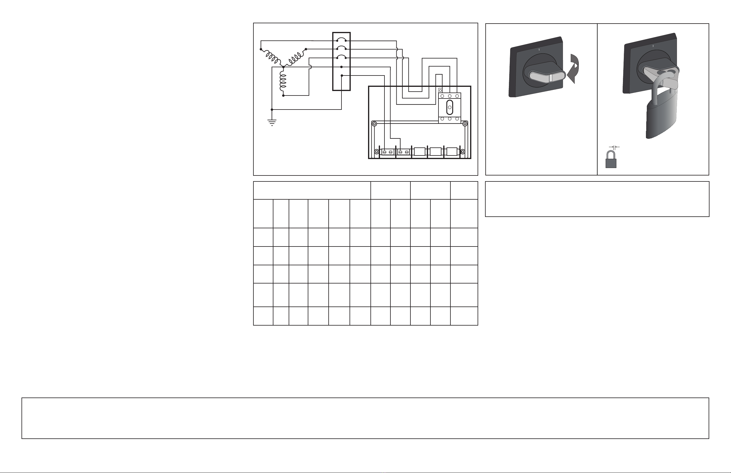
NOTE: The lockout feature of the disconnect switch will accommodate a
lock-shaft diameter of 0.20 in. - 0.31 in. , 5-8 mm (FIGURE 2).
1. Identify the device or load to be protected: The 52000 Panel should be located as close
as possible to the electrical panel serving the load to be protected in order to minimize
connection lead length resistance and inductance.
2. Identify the electrical system in use: This SPD panel is compatible with 3 Phase, 4 Wire
with Ground WYE configurations. The 52120-7MS and 52120-7CS series are compatible
with 120/208V AC WYE and the 52277-7MS and 52277-7CS are compatible with
277/480V AC WYE congurations (FIGURE 1).Matching SPD module and line voltages is
critical! Identify the system in use by measuring L-N and L-L voltages.
CAUTION: VOLTAGE MEASUREMENTS CAN BE DANGEROUS TO LIFE
AND/OR PROPERTY!
CONFIRM THAT THE MAXIMUM MEASURED VOLTAGES DO NOT EXCEED THE AC
RMS VOLTAGE RATING SPECIFIED ON THE 52000 REPLACEABLE MODULES, OR
DAMAGE MAY OCCUR TO THE MODULES.
3. Cutting Access Holes: Cut holes for conduit in panel using approved metal cutting tools.
Prevent any metallic filings from remaining inside the panel. If any metallic filings enter
panel, care must be exercised to remove them using a vacuum device or other
tools, as required.
Mount securely: Refer to the “Panel Mounting” Instruction Sheet enclosed.
Conduit Installation: Conduit should be installed with lock nut and bushing. Lock nut
should be adjusted so that bushing secures properly, and conduit and bushing extend as
little as possible into the enclosure.
4. Connections: NOTE: Maximum wire size is #3 AWG. The SPD Panel is connected
through dedicated circuit breakers at 30 amps. For maximum surge protection the SPD
Panel should be mounted as close as possible (no more than 18 inches) from the circuit
breaker panel. Use wire size #10 to #3 AWG stranded. In a variation of this connection,
the panel circuit breakers can also feed a load by connecting the SPD panel to the circuit
within an approved connection enclosure. In this case, the circuit breakers must be rated
for this load. This facilitates SPD disconnection for installation or maintenance without
interrupting power to the load. It should be noted that during installation or maintenance
of the 52000 SPD Panel, the circuit breakers which feed the 52000 must be opened,
therefore power to the load will be momentarily disconnected.
Phase A, B & C leads ONLY - With the line POWER OFF, connect Phase A, B and C leads
to the upper terminals on the disconnect switch (18 in.-lbs).
Neutral and Ground ONLY - Remove Terminal Block Cover and connect leads using the
largest stranded wire size possible (#10 to #3 AWG) as illustrated in FIGURE 1. Power
leads may be connected to L1, L2, and L3 without regard to phase A, B, or C.
Replace terminal block cover.
Screw terminal torque requirements: #10 AWG (35 in.-lbs.), #8 AWG (40 in.-lbs.),
#3-#6 AWG (45 in.-lbs.).
5. Conduit attachment: A 2-inch hole in the enclosure is recommended to be used for
In-Out conduit connection.
CAUTION: THE ENCLOSURE MUST BE PROPERLY GROUNDED BY USE OF #10 AWG
MINIMUM SIZE COPPER WIRE ROUTED TO THE “G” TERMINAL LUG.
6. Attaching the connection leads - SPD to power lines:
WARNING: TO AVOID FIRE, SHOCK OR DEATH: TURN OFF POWER AT CIRCUIT
BREAKER OR FUSE AND TEST THAT THE POWER IS OFF BEFORE WORKING
ON THE SPD PANEL, SUCH AS WHEN CHANGING FUSES AND INSERTING OR
REMOVING REPLACEABLE MODULES.
NOTE: Power to the modules is disconnected when the disconnect switch is set to
the OFF position.
The ground terminal within the SPD Panel is connected to the metal enclosure. For
isolated ground systems, the isolated ground wire should not be connected to the In-Out
ground terminals. However, as indicated in step 5, the enclosure must be grounded via a
ground conductor to the ground terminal. With the power OFF, connect phase leads to L1,
L2, and L3 as indicated in step 4. Connect the neutral, for WYE systems, to the neutral
terminal. Connect ground to ground terminal.
Avoid sharp bends: Lead wire insulation should not be cut or damaged except to expose
ends for connection.
7. Remote connection:
• Relay status circuit and contacts rated at 7 Amps. The voltage rating is 240VAC or
30VDC. Contacts accommodate 20-12 AWG wire secured to terminals using 3.5 in.-lbs.
of torque. Wiring must be rated 600 VAC, dressed and secured away from live parts
and protected from sharp edges and door entrapment. Hole must be cut in enclosure for
conduit connection. If surge protection fails, continuity will be between the “NO” and “C”
contacts.
NOTE: If surge suppression failure has occurred, a transient surge has exceeded the
rating of the module and it should be replaced immediately.
• A 7/8 inch hole cut on the hinged side of the enclosure is recommended for the Remote
Supervisor Panel connections. See Remote Supervisor Panel Instructions for its
connection method.
8. Battery Installation: A 9-Volt alkaline battery is included in the shipping carton. The
purpose of the 9-Volt battery is to power the diagnostic warning circuitry in the event of
a power failure or multiple fuse failures. Remove the battery holder from the diagnostic
assembly. Insert the 9-Volt battery (be sure to follow the polarity markings on the battery
compartment), and slide the battery holder back in.
9. Secure modules and replace terminal block cover: Be certain all SPD Modules are
tightly in place and remove any extra materials. Close and secure enclosure cover door
before applying power.
10. Activate the system by turning AC power and Disconnect Switch ON: The Green
Module Status lights should be illuminated and visible through the ports in the enclosure
door, and all other lights should be OFF. If problems are encountered that can not be
resolved using the Problem Isolation Procedure printed on the inside of the enclosure
door, contact Leviton Technical Support: 1-800-824-3005.
11. Diagnostic Test: Press and hold down the test button. The Red warning indicator should
blink, the audible tone signal should beep, the Yellow low battery light should illuminate,
and the Remote Supervisor Panel warning indicator, if wired in, will be activated. Release
the test button.
12. Surge Counter Test: If the 52000 Panel has a LCD surge counter on it’s front panel,
press it’s “Reset” switch, then the “Test” switch. The display should register surge counts
each time the “Test” switch is depressed. The “Reset” switch should be depressed
whenever the LCD display is at a maximum (the LCD unit’s red LED will be illuminated).
“Reset” may be depressed anytime to clear the display.
NOTE: If there is a surge event with an amplitude of 800Vpk (1.2/50 & 8/20 combination
wave) or higher, then the unit will record the number of surges and show the total number
on the counter display.
SERVICING INSTRUCTIONS
Leviton Series 52000 SPD Servicing Instruction Procedure: Carefully read these
instructions as well as the Module and Fuse Replacement Instruction Procedure before
attempting service.
CAUTION: BEFORE OPENING SPD ENCLOSURE COVER, POWER MUST BE TURNED
OFF. FIRE, SHOCK OR DEATH CAN RESULT FROM INCORRECT SERVICING. IT IS
RECOMMENDED THAT THE 52000 SPD PANEL PROTECTION SYSTEM BE SERVICED
BY AN ELECTRICIAN. FUSES AND MODULES CAN BE SERVICED AND REPLACED BY
TURNING DISCONNECT SWITCH OFF.
Diagnostic Indicator Functions: Table 1 lists the diagnostic functions of the 52000 series
panels.
Module Diagnostics: Each module contains a Green LED for each mode. When illuminated,
they indicate that the module is properly seated, power for that phase is present, and the
protection fuse for that mode is intact. Modules should be replaced as soon as possible, after
a failure is noted (unlit Green LED). Absence of illuminated LEDs indicates either a loss of
power or a blown fuse due to excessive transients, such as due to a direct lightning strike.
When this occurs, see the Module LED/Fuse Correspondence Chart (located on the inside
panel door) for the list of the Green LED indicators and their designated fuses.
Fault Indication: A flashing Red warning LED, in addition to an audible beep tone, indicates
loss of power to the modules. This can be due to the absence of main phase power, or a