DI-000-ZMDSW-00D
©2010LevitonMfg.
Co.,Inc.
ForTechnicalAssistanceCall:1-800-959-6004oremail:LMST[email protected](U.S.A.Only)LIMITED 2 YEAR WARRANTY AND EXCLUSIONS
Leviton warrants to the original consumer purchaser and not for the benet of anyone else that this product at the time of its sale by Leviton is free of defects in materials and workmanship under normal and proper use for two years from
the purchase date. Leviton’s only obligation is to correct such defects by repair or replacement, at its option, if within such two year period the product is returned prepaid, with proof of purchase date, and a description of the problem
to Leviton Manufacturing Co., Inc., Att: Quality Assurance Department, 20497 S.W. Teton Ave, Tualatin OR 97062. This warranty excludes and there is disclaimed liability for labor for removal of this product or reinstallation. This
warranty is void if this product is installed improperly or in an improper environment, overloaded, misused, opened, abused, or altered in any manner, or is not used under normal operating conditions or not in accordance with any
labels or instructions. There are no other or implied warranties of any kind, including merchantability and tness for a particular purpose, but if any implied warranty is required by the applicable jurisdiction, the duration of
any such implied warranty, including merchantability and tness for a particular purpose, is limited to two years. Leviton is not liable for incidental, indirect, special, or consequential damages, including without limitation, damage to,
or loss of use of, any equipment, lost sales or prots or delay or failure to perform this warranty obligation. The remedies provided herein are the exclusive remedies under this warranty, whether based on contract, tort or otherwise.
TESTING THE WIRING:
Toassureproblem-freestart-up,itisimportanttocheckthesystemwiring,priortohookingupanycontrolstations,forproperconnections,shortsandopens.
Thefollowingprocedureisrecommended:
Step1:Testthefollowingwirepairsforshortsateachstationlocation,usinganohmmeterorothercontinuitytester.
1-2Open
2-3Open
3-4Open
Step2:Repairanyshortcircuitsbeforecontinuing.
Step3:Installwirejumpers,onepairatatime(notsupplied)totheLume-Net®connectoroneitherendofthecablerunbetweenpins1-2,then2-3,then3-4.
Step4:Retesteachofthefollowingwirepairsateachconnector:
1-2Short
2-3Short
3-4Short
Step5:Makeanynecessaryrepairsandremovewirejumpersbeforecontinuing.
STATION ADDRESSING – GENERAL:
Everystationneedstobegivenauniqueaddressbetween1and127.IfastationaddressissettoZeroitwillnotparticipateon
thenetwork.TheswitchissettothebinaryrepresentationoftheIDnumber.Thebinary1’scolumnisleft-most(leverlabeled"1").
Theswitchleversarenumbered1-8,theserepresentthefollowing:
Lever=Value
1=1 2=2
3=4 4=8
5=16 6=32
7=64 8=Notused-MustbeOFF
Addthevalueofeachleverinthe"ON"positiontodeterminetheIDnumber(decimalform).
Forexample:
Tosettheaddressto39,thefollowingswitchesneedtobeinthe"ON"position:1,2,3,6=1+2+4+32=39
ASSIGNIING THE STATION:
Determinethestationsaddressandsetitonthebackoftheunit.Ifthereisonlyoneunitintheroomorspace
controllingthesameloads,proceedtotheInstallationStep.MultipleZ-MAXTMdigitalswitchescanbeslavedback
toaZ-MAXTMdigitalswitch,thusmimickinga3wayor4wayapplicationandonlyhavingtoprogramoneswitch
inputattherelaypanel.Inthiscase,followthesesteps:
Tosettheremoteidenticationnumber,andslaveittoamasterZ-MAXDigitalSwitch:
1. Withthestationunplugged,settheremoteslavestation’sDIPswitchestotheaddressofthemasterstation
thatitistobeslavedwith.
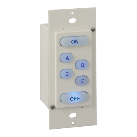
2. Withthestationunplugged,pressandholdtheUPPERmostLEFTbutton.This"InitButton"mustbe
continuouslyheldduringthenextfewsteps.
3. Whileholdingthebuttondown,powerupthestationbypluggingitbackin.
4. TheGreenfrontpanelLED'sremaindark(OFF),whiletheRedLEDonthebackturnsON.TheRedLED
remainsONwhiletheunitwaitsfor10seconds.
5 ThestationwillindicatethattheIDhasbeensaved/recordedbytheGreenfrontpanelLED'sblinkingtwice
andthebackRedLEDturningOFF,thenON,thenOFFagain.
6. Takeyourngeroffofthe"InitButton".
7. NowunplugtheunittoendtheSlaveNodeIDcongurationprogramming.
8. Withthestationunplugged,settheDIPswitchestothedesiredIDnumberforthisparticularremotestation
(everystationonthenetworkmusthaveitsownuniquestationnumberbetween1-127).
9. Powerupthestationbypluggingitbackin,anditshouldbereadytooperatenormally.Whenthestationrst
powersupunderoperatingconditions,alloftheGreenLED'sashonmomentarilyandthengooff;andthe
backRedLEDashesrapidlyuntiltheLuma-Net®networkbecomesstable/operationalatwhichpointtheback
RedLEDashesON/OFFbrieyaboutoncepersecond...sortofaheartbeat/normaloperationindication.
10. Ifyou’vemadeanerrorinprogrammingthestation’sownIDortheSlaveID,thestationwillasherrorcodes
onalloftheLED's(bothfrontpanelandback).ThefollowingErrorCodesareobservable.Thepatternisblinked
andthenrepeatedafterapause.
a.1blinkofallLED's=StationNetIDiszeroortoohigh
b.2blinksofallLED's=1STSlaveIDiszeroortoohigh
c.3blinksofallLED's=BothStationNetIDandSlaveIDarethesame
11. ToreprogramthestationbacktoaMaster,unplugtheconnector,setthedipswitchtothedesirednetworkID
andfollowsteps2-7.
INSTALLATION:
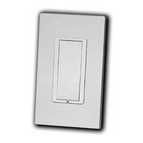
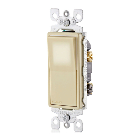
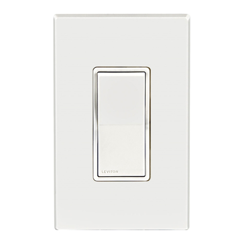
Securelymounttheentrystationusingthescrewsprovided.Ifyouareusingascrewlesssnaponplate,removethe
centertabsofthestrapasshowninFig.1.
NOTE:ForCat.Nos.ZMDSW-S1W,-S2W,-S3W,-S4Wand-S5W,a35mmorpreferred47mmdeep2-tabbackboxisrequired
.RefertoFig.2.
PROGRAMMING/OPERATION:
AllprogrammingoftheZ-MAXdigitalswitchesaredoneattherelaycabinet.PleaserefertoLIT-ZMAXN-000fortheremainderofthesetupandprogramming.
O
F
F
1 + 2 + 4 + 8 + 16 + 32 + 64 + 128
Net ID
(Line indicates the silkscreen under the dipswitch)
1 2 3 4 5 6 7 8
O N
Remove the center tab
from top and bottom prior
to installation of Snap-on plate
Snap-on plate
Drain/Shield - Insulated & tied together
(Ground at one point only - probably an end)
Phoenix/Luma-Net®Connector
Install termination
jumper if last station on
Wiring for runs shorter than 1,000 ft.
56
1
234
REM+
REM -
COM
TERM
LOCK
+V
1
2
3
4
5
6
Dimmer or
Relay Cabinet
Equipped
with
Luma-Net®
Termination Jumper Locations
Terminate Luma-Net®
Ground Shield
3" x 3" back box Mounting configuration
for Cat. Nos. ZMDSW-S1W,
-S2W, -S3W, -S4W, -S5W
Snap-on plate
Use 35mm or preferred
47mm deep 2-tab back box
FIG. 1
FIG. 2
