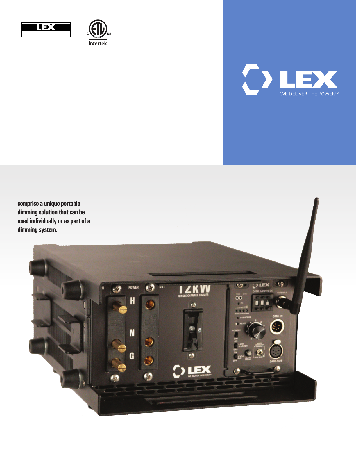
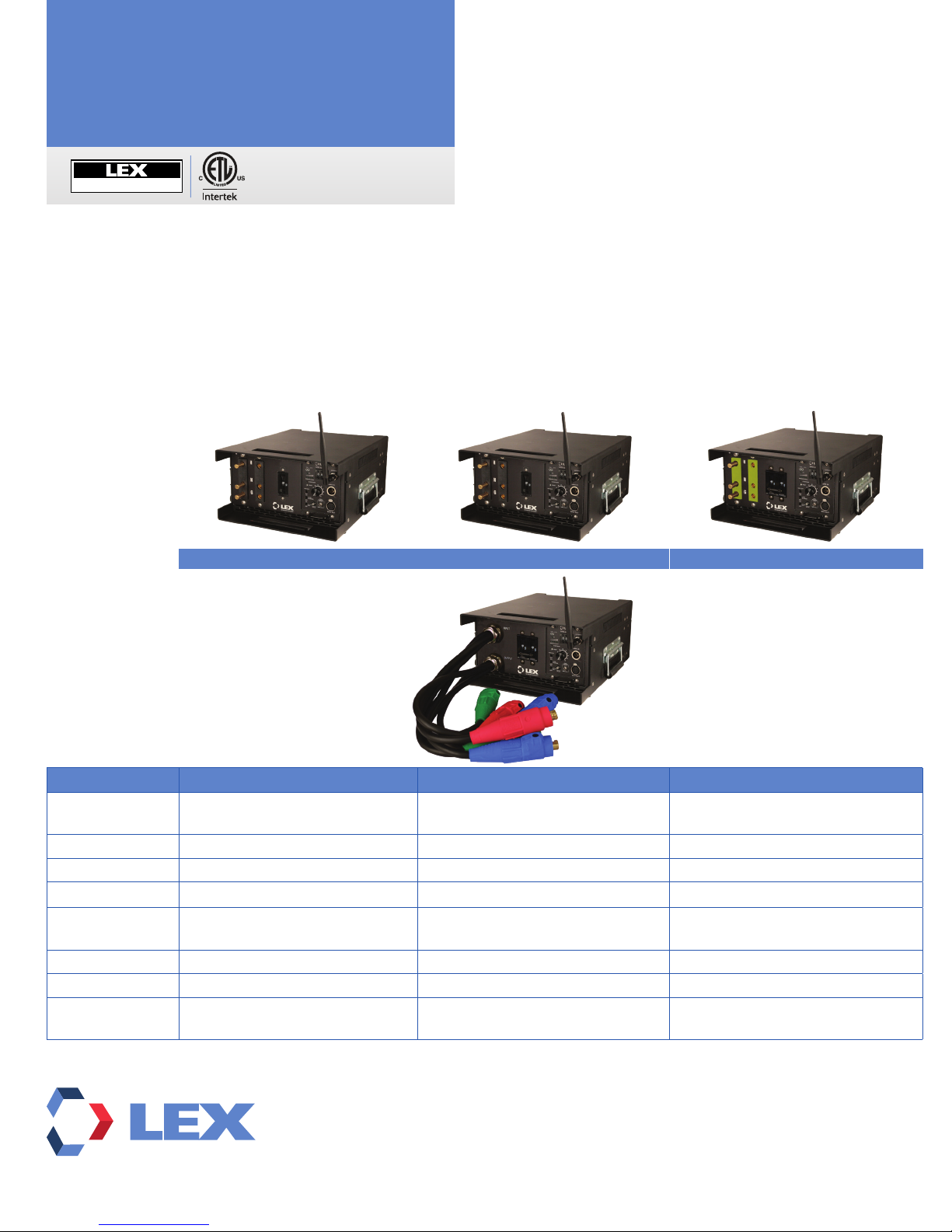
Portable Single Dimmers
Maintenance
TheLexProductsPortableSingleDimmersaredesignedtobelowmaintenance.However,severalprecautionarystepswillprolongthe
life of the electronic components.
• Wheneverpossible,limittheunit’sexposuretohighambienttemperatures.
• Take care not to drop the device and always protect the controls and connectors from damage.
• Do not allow liquid of any kind to enter the unit.
• Allscrewsandconnectionsshouldbecheckedandtightened,ifnecessaryonaregularbasis,especiallyinrentalandlocation
applications.
• Iftheunitaccumulatesdust,disconnectitfrompowerandcleanusingcompressedair.
• Always disconnect dimmer from power before performing any maintenance operation.
Troubleshooting
If the portable dimmer does not operate as expected:
ȽCheck the power source and check all cables and connectors.
ȽEnsure the circuit breaker is on.
ȽConrmthatthecontrolledloadoperatesfromaconstantpowersupply.
ȽConrmthatanyremoteconsoleissendingvalidDMX512-Adata.
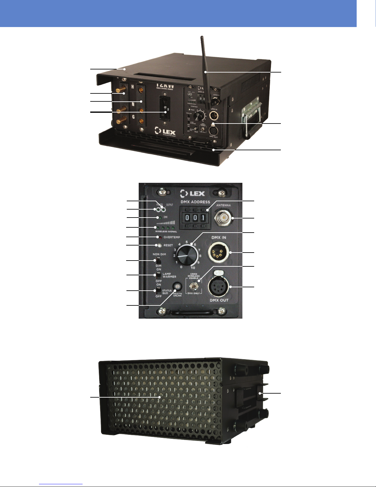
Control indicators to not illuminate:
ȽConrmthatpowerispresentattheunit.
Rotary dial does not raise and lower the lighting level:
ȽCheck the power source.
ȽMake sure the dimmer is in DIM mode (Toggle DIM/NON-DIM selector switch to the DIM position).
Unit does not respond to remote DMX512-A input:
ȽCheck all control cabling and check that DMX LED is illuminated to indicate presence of control signal.
ȽMake sure that the Manual rotary dial is set at ‘-0’ (slider is all the way counter clockwise of its run).
Connected load switches on and off instead of dimming:
ȽConrmthattheDIM/NON-DIMselectorswitchisintheDIMposition.
The dimmer does not respond to the user controls:
ȽCheck all control cabling and check that DMX LED is illuminated to indicate presence of control signal.
ȽIfoperatinginManualmode,spintherotarydialthefullrangeofrotationrepeatedlytoclearpossibledirt,dustordebris.
ȽEnsuretheOVERTEMPLEDisnotilluminated.Iflit,movetheunittoacoolerlocation.
ȽIftheabovesuggestionsareunsuccessful,resettheelectronicsbypressingtheResetbuttononthecontrolpanel.
Connected load is ghosting and will not shut off:
ȽThe Lamp Warmer selector switch pre-heat level has been set and is maintaining a level of 5%. Set to the Lamp Warmer
selector switch to the OFF (down) position.
ȽEnsure the Manual rotary dial is set at ‘-0’ and the DMX512-A signal is set to zero.
Load is stuck on and does not dim or switch off:
ȽCheck to see if the NON-DIM mode is activated and the relay has been turned on manually.
ȽIftheloadremainson,thepowerdevicemayhavefailed.ContactTechnicalServicesat1.855.LEX.1002
Technical Support
The staff at Lex Products is willing and available to help in any way possible. If you have questions or need technical advice or
suggestionsregardingthisproduct,pleasecontactLexat1.855.LEX.1002ore-mailLexat
[email protected].Businesshours
areMondaythroughFriday,8:30am–5:00pmETandPT.