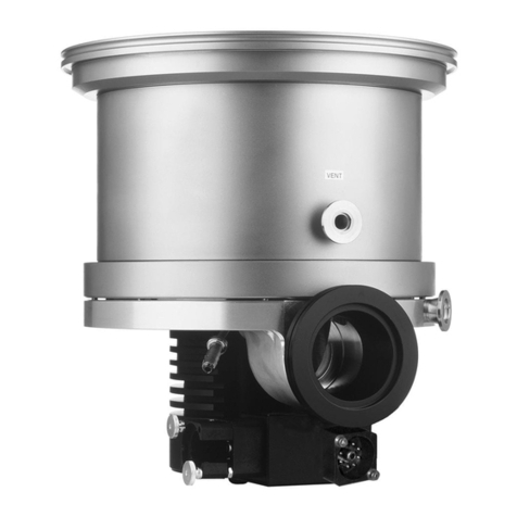
LEYBOLD RUVAC WS 251 User manual
Other LEYBOLD Water Pump manuals

LEYBOLD
LEYBOLD SOGEVAC SV1200 User manual

LEYBOLD
LEYBOLD SOGEVAC SV45 FP User manual

LEYBOLD
LEYBOLD SOGEVAC SV10B User manual
LEYBOLD
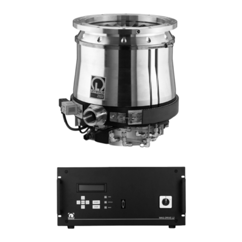
LEYBOLD MAG W 1600 C User manual

LEYBOLD
LEYBOLD 312 31T User manual

LEYBOLD
LEYBOLD TURBOVAC TW 250 S User manual
LEYBOLD
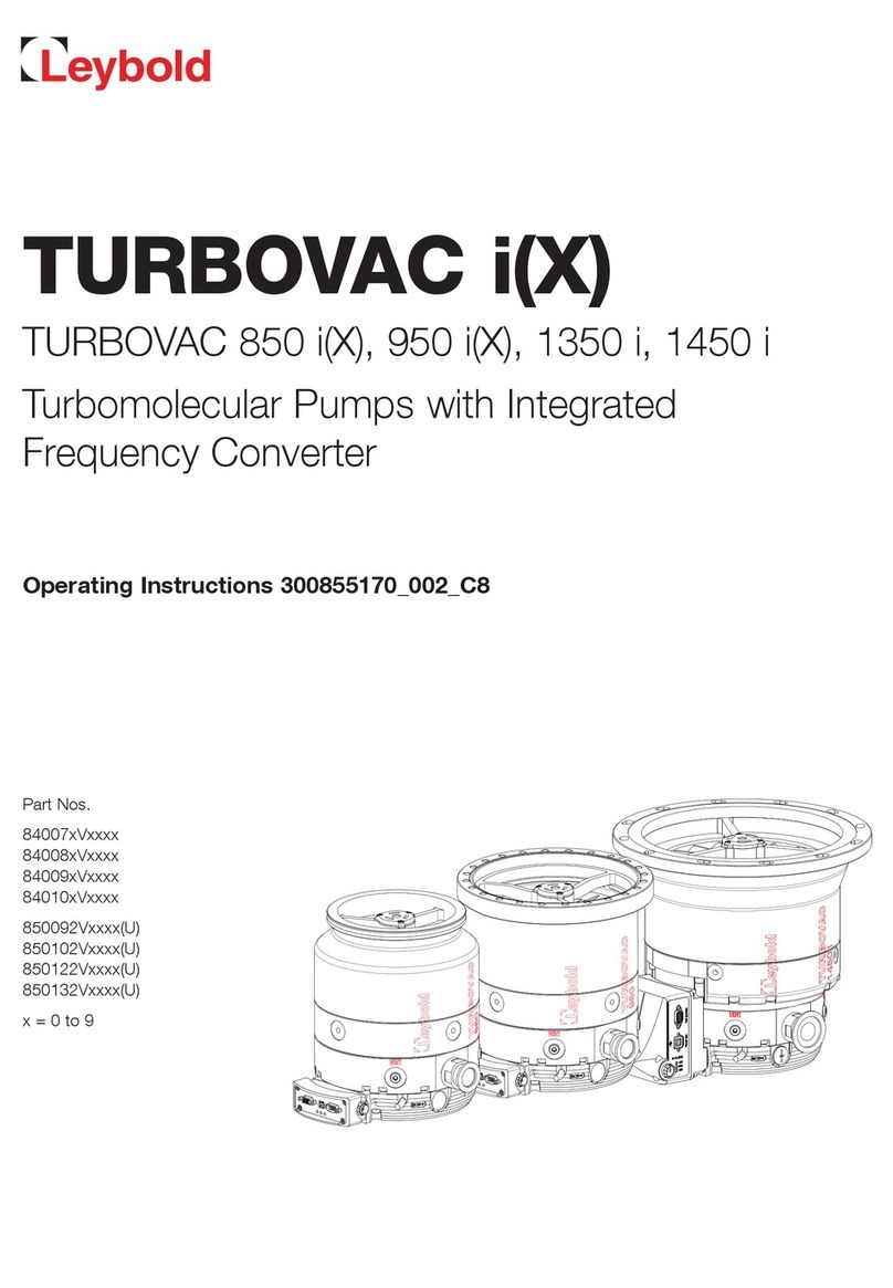
LEYBOLD TURBOVAC i(X) User manual
LEYBOLD
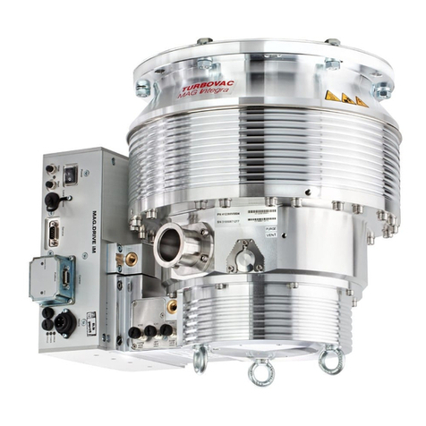
LEYBOLD MAG Series User manual

LEYBOLD
LEYBOLD TURBOVAC 340 M User manual

LEYBOLD
LEYBOLD SOGEVAC SV300 FP User manual
LEYBOLD
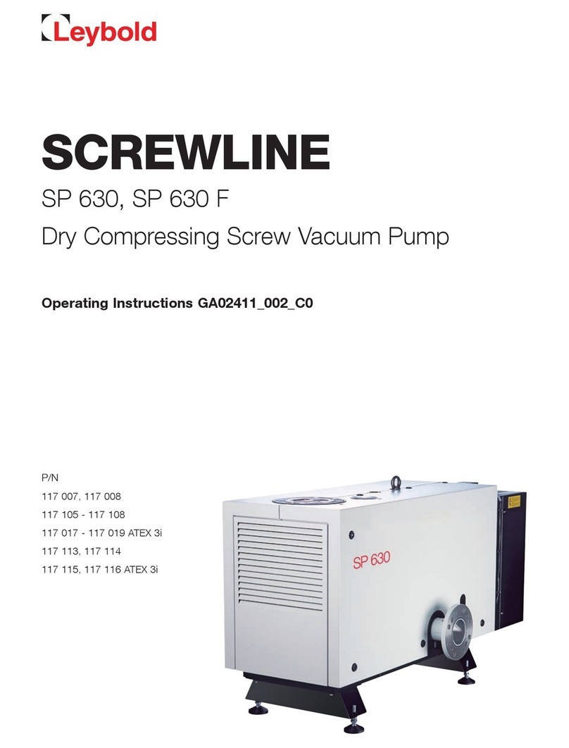
LEYBOLD SCREWLINE SP 630 F User manual

LEYBOLD
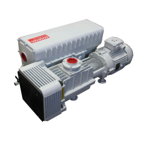
LEYBOLD SOGEVAC SV40 B User manual
LEYBOLD
LEYBOLD SOGEVAC SV300 B User manual

LEYBOLD
LEYBOLD TURBOVAC 50 User manual
LEYBOLD
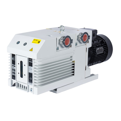
LEYBOLD TRIVAC B User manual

LEYBOLD
LEYBOLD SOGEVAC SV65 B User manual

LEYBOLD
LEYBOLD Trivac L User manual
LEYBOLD
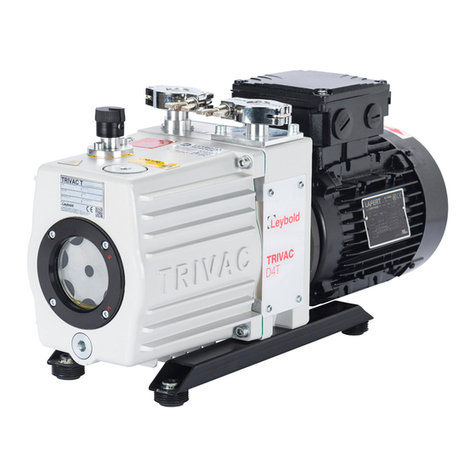
LEYBOLD TRIVAC T Series User manual

LEYBOLD
LEYBOLD SOGEVAC SV25 B User manual

LEYBOLD
LEYBOLD TRIVAC E2 User manual
Popular Water Pump manuals by other brands

Watershed Innovations
Watershed Innovations HYDRAPUMP SMART FLEX Instructional manual

Graco
Graco Modu-Flo AL-5M instructions

Messner
Messner MultiSystem MPF 3000 operating instructions

Xylem
Xylem Bell & Gossett WEHT0311M Installation, operation and maintenance instructions

WilTec
WilTec 50739 Operation manual

Franklin Electric
Franklin Electric Little Giant 555702 HRK-360S instruction sheet

Ingersoll-Rand
Ingersoll-Rand PD02P Series Operator's manual

VS
VS ZJ Series Operating instruction

Flotec
Flotec FPZS50RP owner's manual

SKF
SKF Lincoln FlowMaster II User and maintenance instructions

Xylem
Xylem Lowara LSB Series Installation, operation and maintenance instructions

Water
Water Duro Pumps DCJ500 Operating & installation instructions

Action
Action P490 Operating instructions & parts manual

Flo King
Flo King Permacore Reusable Carbon Bag Disassembly. & Cleaning Instructions

ARO
ARO ARO PD15P-X Operator's manual

Pumptec
Pumptec 112V Series Operating instructions and parts manual

Virax
Virax 262070 user manual

Neptun
Neptun NPHW 5500 operating instructions

