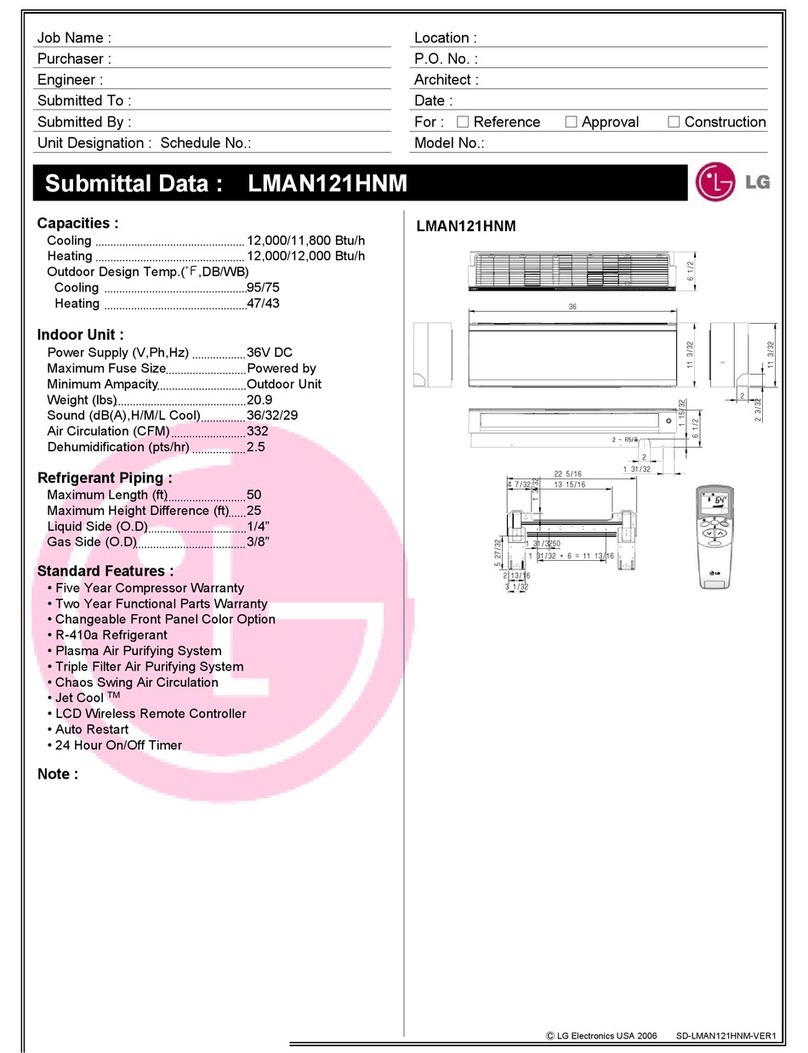
LG ABNW366KSA1 User manual

LG
Ceiling Duct Type
Air Conditioner
SERVICE MANUAL
LG
CAUTION
website http://www.lgservice.com
• BEFORE SERVICING THE UNIT, READ THE SAFETY
PRECAUTIONS IN THIS MANUAL.
• ONLY FOR AUTHORIZED SERVICE PERSONNEL.
MODELS: ABNW366KSA1 ABUW366KSA1
ABNW426KSA1 ABUW426KSA1
ABNW486KSA1 ABUW486KSA1
ABNW606LTA1 ABUW606LTA1
ABNW366KSA3 ABUW366KSA3
ABNW426KSA3 ABUW426KSA3

2Ceiling Duct type Air Conditioner
Ceiling Duct type Air Conditioner Service Manual
TABLE OF CONTENTS
Safety Precautions ...................................................................................................................3
Model Number Nomenclature..................................................................................................8
Product Specifications (cooling & Heating)...........................................................................9
Dimensions .............................................................................................................................11
Refrigeration Cycle Diagram .................................................................................................15
Wiring Diagram.......................................................................................................................17
Electronic control device ......................................................................................................21
Functions ................................................................................................................................22
Operation Details....................................................................................................................24
Installation of Indoor, Outdoor Unit......................................................................................27
Connecting Pipes to the Outdoor Unit .................................................................................38
Checking the Drainage...........................................................................................................38
Connecting Cables between Indoor Unit and Outdoor Unit...............................................39
Air Purging of the Connecting Pipes and the Indoor Unit..................................................42
Group Control .........................................................................................................................43
Two Thermistor system .........................................................................................................43
Cycle Troubleshooting Guide................................................................................................44
Exploded View and Replacement Parts List ........................................................................63

Safety Precautions
Service Manual 3
Safety Precautions
To prevent injury to the user or other people and property damage, the following instructions must
be followed.
■Incorrect operation due to ignoring instruction will cause harm or damage. The seriousness is
classified by the following indications.
■Meanings of symbols used in this manual are as shown below.
This symbol indicates the possibility of death or serious injury.
This symbol indicates the possibility of injury or damage.
■Installation
Be sure not to do.
Be sure to follow the instruction.
Do not use a defective or underrat-
ed circuit breaker. Use this appli-
ance on a dedicated circuit.
• There is risk of fire or electric shock.
For electrical work, contact the
dealer, seller, a qualified electri-
cian, or an Authorized Service Cen-
ter.
• Do not disassemble or repair the
product. There is risk of fire or elec-
tric shock.
Always ground the product.
• There is risk of fire or electric shock.
Install the panel and the cover of
control box securely.
• There is risk of fire or electric shock.
Always install a dedicated circuit
and breaker.
• Improper wiring or installation may
cause fire or electric shock
Use the correctly rated breaker or
fuse.
• There is risk of fire or electric shock.

Safety Precautions
4Ceiling Duct type Air Conditioner
■Operational
Do not modify or extend the power
cable.
• There is risk of fire or electric shock.
Do not install, remove, or re-install
the unit by yourself (customer).
• There is risk of fire, electric shock,
explosion, or injury.
Be cautious when unpacking and
installing the product.
• Sharp edges could cause injury. Be
especially careful of the case edges
and the fins on the condenser and
evaporator.
For installation, always con-
tact the dealer or an Autho-
rized Service Center.
• There is risk of fire, electric shock,
explosion, or injury.
Do not install the product on a
defective installation stand.
• It may cause injury, accident, or
damage to the product.
Be sure the installation area
does not deteriorate with age.
• If the base collapses, the air condi-
tioner could fall with it, causing
property damage, product failure,
and personal injury.
Do not let the air conditioner
run for a long time when the
humidity is very high and a
door or a window is left open.
• Moisture may condense and wet or
damage furniture.
Take care to ensure that power
cable could not be pulled out or
damaged during operation.
• There is risk of fire or electric
shock.
Do not place anything on the
power cable.
• There is risk of fire or electric
shock.
Do not plug or unplug the power
supply plug during operation.
• There is risk of fire or electric shock.
Do not touch(operate) the product
with wet hands.
• There is risk of fire or electrical shock.
Do not place a heater or other
appliances near the power cable.
• There is risk of fire and electric shock.

Safety Precautions
Service Manual 5
Do not allow water to run into elec-
tric parts.
• It may cause There is risk of fire, fail-
ure of the product, or electric shock.
Do not store or use flammable gas or
combustibles near the product.
• There is risk of fire or failure of product.
Do not use the product in a tightly
closed space for a long time.
• Oxygen deficiency could occur.
Gasolin
When flammable gas leaks,
turn off the gas and open a win-
dow for ventilation before turn
the product on.
• Do not use the telephone or turn
switches on or off.
There is risk of explosion or fire
If strange sounds, or small or
smoke comes from product. Turn
the breaker off or disconnect the
power supply cable.
• There is risk of electric shock or
fire.
Stop operation and close the window
in storm or hurricane. If possible,
remove the product from the window
before the hurricane arrives.
• There is risk of property damage,
failure of product, or electric shock.
Do not open the inlet grill of the prod-
uct during operation.
(Do not touch the electrostatic filter, if
the unit is so equipped.)
• There is risk of physical injury, electric
shock, or product failure.
When the product is soaked (flood-
ed or submerged), contact an
Authorized Service Center.
• There is risk of fire or electric shock.
Be cautious that water could not
enter the product.
• There is risk of fire, electric shock, or
product damage.
Ventilate the product from time to time when operating
it together with a stove, etc.
• There is risk of fire or electric shock.
Turn the main power off when cleaning or maintaining
the product.
• There is risk of electric shock.

Safety Precautions
6Ceiling Duct type Air Conditioner
When the product is not be used for a long time, dis-
connect the power supply plug or turn off the
breaker.
• There is risk of product damage or failure, or unintended
operation.
Take care to ensure that nobody could step on or fall
onto the outdoor unit.
• This could result in personal injury and product damage.
■Installation
Always check for gas (refrigerant) leak-
age after installation or repair of prod-
uct.
• Low refrigerant levels may cause fail-
ure of product.
Install the drain hose to ensure
that water is drained away proper-
ly.
• A bad connection may cause water
leakage.
Keep level even when installing the
product.
• To avoid vibration or water leakage.
90°
Do not install the product where the
noise or hot air from the outdoor unit
could damage the neighborhoods.
•It may cause a problem for your
neighbors.
Use two or more people to lift
and transport the product.
•Avoid personal injury.
Do not install the product
where it will be exposed to sea
wind (salt spray) directly.
•It may cause corrosion on the
product. Corrosion, particularly on
the condenser and evaporator fins,
could cause product malfunction or
inefficient operation.
■Operational
Do not expose the skin directly to cool air for long peri-
ods of time. (Don't sit in the draft.)
•This could harm to your health.
Do not use the product for special purposes, such as pre-
serving foods, works of art, etc. It is a consumer air condi-
tioner, not a precision refrigeration system.
•There is risk of
damage or
loss of property.

Safety Precautions
Service Manual 7
Do not block the inlet or outlet of
air flow.
•It may cause product failure.
Use a soft cloth to clean. Do not
use harsh detergents, solvents,
etc.
•There is risk of fire, electric shock, or
damage to the plastic parts of the prod-
uct.
Do not touch the metal parts of the
product when removing the air filter.
They are very sharp!
•There is risk of personal injury.
Wax
Thinner
Do not step on or put anyting on
the product. (outdoor units)
•There is risk of personal injury and fail-
ure of product.
Always insert the filter securely. Clean the
filter every two weeks or more often if
necessary.
•A dirty filter reduces the efficiency of
the air conditioner and could cause
product malfunction or damage.
Do not insert hands or other objects through
the air inlet or outlet while the product is
operated.
•There are sharp and moving parts that
could cause personal injury.
Do not drink the water drained
from the product.
•It is not sanitary and could cause seri-
ous health issues.
Use a firm stool or ladder when
cleaning or maintaining the prod-
uct.
•Be careful and avoid personal injury.
Replace the all batteries in the remote
control with new ones of the same type.
Do not mix old and new batteries or dif-
ferent types of batteries.
•There is risk of fire or explosion
Do not recharge or disassemble the batteries. Do not
dispose of batteries in a fire.
•They may burn or explode.
If the liquid from the batteries gets onto your skin or
clothes, wash it well with clean water. Do not use the
remote if the batteries have leaked.
•The chemicals in batteries could cause burns or other health
hazards.

Model Number Nomenclature
8Ceiling Duct type Air Conditioner
Model Number Nomenclature
12
Code Type Code of Model Meaning
1 Producing Center/ A~Z
L: ChangWon R22, A: ChangWon R410A, C: ChangWon R407C
Refrigerant
2 Type of Air conditioner A~Z B: Ceiling Duct Type Air conditioner
3 Cooling/Heating A~Z
C: C/O, H: H/P, X: C/O + E/H, Z: H/P + E/H, W: Inverter + H/P
4,5 Capacity(Btu/h) 1~9 Cooling/Heating Capacity
Ex. "48" ➔48,000Btu/h
6 Electric Range 1~9 Electric Standard [V/Hz/Phase]
1 : 115/60/1 2 : 220/60/1 3 : 208-230/60/1
5 : 200-220/50/1 6 : 220-240/50/1 7 : 100/50(60)/1
8 : 380-415/50/3 9 : 380/60/3 A : 220/50/3
B : 208-230/60/3 C : 575/60/3 D : 440-460/60/3
E : 265/60/1 F : 200/50-60/1
7 Chassis A~Z Name of tool of unit
8 LG/OEM Brand A~Z L: LG Brand M: 1st OEM Brand
G: 2nd LG Brand N: 2nd OEM Brand
9 Function A~Z
10 Serial No. 0~9
-
Basic A
Low Ambient B
Plasma Filter C
Plasma Filter + Drain Pump D
E
Low Ambient + Drain Pump F
Low Static Motor G
Plasma Filter + Low Ambient H
Plasma Filter + Low Ambient + Drain Pump J
K
L
M
N
Drain Pump P
Q
R
345678910

Product Specifications (cooling & Heating)
Service Manual 9
1, 220-240, 50 1, 220-240, 50 1, 220-240, 50
8,568(34,000) 7,747(30,743) 10,080(40,000)
9,964 9,010 11,723
4,100 3,870 4,700
9,324(37,000) 8,410(33,370) 12,096(48,000)
10,844 9,780 14,067
3,500 3,450 4,400
17.5 17.5 20
15 18 19.5
533/467/383 533/467/383 767/667/583
533/467/383 533/467/383 767/667/583
2,830 2,830 3,500
22.6 22.6 22.6
3*5.5 3*5.5 3*8.5
4*1.25 4*1.25 4*1.25
L.C.D Wired L.C.D Wired L.C.D Wired
L.E.V L.E.V L.E.V
Ye s Ye s Ye s
24 Hours On/Off 24 Hours On/Off 24 Hours On/Off
Ye s Ye s Ye s
Ye s Ye s Ye s
Ye s Ye s Ye s
Optional Optional Optional
Ye s Ye s Ye s
Optional Optional Optional
Ye s Ye s Ye s
Ye s Ye s Ye s
Optional Optional Optional
Ye s Ye s Ye s
Ye s Ye s Ye s
3/8(9.52) 3/8(9.52) 3/8(9.52)
5/8(15.88) 5/8(15.88) 3/4(19.05)
1040*350*560 1040*350*560 1040*350*560
870*1060*320 870*1060*320 900*1165*370
37 37 37
80 80 105
Power Source Ø, V, Hz
Cooling Capacity kcal/h(BTU/h)
W
Input W
Heating Capacity kcal/h(BTU/h)
W
Input W
Rated Load Amp. Cooling A
Heating A
Air Volumn Cooling(H/M/L) L/S
Heating(H/M/L)
Refrigerant(R410A) g
Drain Hose In. Dia mm
Main Cable No. X mm2
Connecting Cable
Remote Control Type
Refigerant Control Type
Fuction Soft Dry
Timer
Self Diagnosis
Deice Operation
Hot Start
Zone Control(Optional)
Central Control(Optional)
Group Control(Optional wiring)
Radio Frequency Control(Optional)
Weekly Programning
Thermistor
Drain Pump(Optional)
Auto changeover(Auto Operation: CL)
Stand-by Consumption 0
Connecting Pipe Liquid Inch
Gas (mm)
Dimension Indoor mm
Outdoor (W x H x D)
Net Indoor Kg
Weight Outdoor
Model
AB-W366KSA1 AB-W366KSA3 AB-W426KSA1
Product Specifications (cooling & Heating)

Product Specifications (cooling & Heating)
10 Ceiling Duct type Air Conditioner
1, 220-240, 50 1, 220-240, 50 1, 220-240, 50
9,106(36,135) 11,592(46,000) 13,840(55,000)
10,590 13,481 16,100
4,590 5,200 6,500
10,920(43,334) 12,852(51,000) 15,100(60,000)
12,700 14,946 17,600
4,400 4,700 5,800
20 23 28
19.5 20.5 26
767/667/583 850/817/767 1083/967/850
767/667/583 850/817/767 1083/967/850
3500 3700 5800
22.6 22.6 22.6
3*8.5 3*8.5 3*8.5
4*1.25 4*1.25 4*1.25
L.C.D Wired L.C.D Wired L.C.D Wired
L.E.V L.E.V L.E.V
Ye s Ye s Ye s
24 Hours On/Off 24 Hours On/Off 24 Hours On/Off
Ye s Ye s Ye s
Ye s Ye s Ye s
Ye s Ye s Ye s
Optional Optional Optional
Ye s Ye s Ye s
Optional Optional Optional
Ye s Ye s Ye s
Ye s Ye s Ye s
Optional Optional Optional
Ye s Ye s Ye s
Ye s Ye s Ye s
3/8(9.52) 3/8(9.52) 3/8(9.52)
3/4(19.05) 3/4(19.05) 3/4(19.05)
1040*350*560 1040*350*560 1120*400*580
900*1165*370 900*1165*370 750*1517*650
37 40 51
105 105 120
Power Source Ø, V, Hz
Cooling Capacity kcal/h(BTU/h)
W
Input W
Heating Capacity kcal/h(BTU/h)
W
Input W
Rated Load Amp. Cooling A
Heating A
Air Volumn Cooling(H/M/L) L/S
Heating(H/M/L)
Refrigerant(R410A) g
Drain Hose In. Dia mm
Main Cable No. X mm2
Connecting Cable
Remote Control Type
Refigerant Control Type
Fuction Soft Dry
Timer
Self Diagnosis
Deice Operation
Hot Start
Zone Control(Optional)
Central Control(Optional)
Group Control(Optional wiring)
Radio Frequency Control(Optional)
Weekly Programning
Thermistor
Drain Pump(Optional)
Auto changeover(Auto Operation: CL)
Stand-by Consumption 0
Connecting Pipe Liquid Inch
Gas (mm)
Dimension Indoor mm
Outdoor (W x H x D)
Net Indoor Kg
Weight Outdoor
Model
AB-W426KSA3 AB-W486KSA1 AB-W606LTA1

Service Manual 11
Dimensions
"A" "B" "C" "D" "E" "F" "G" "J" "K" "P" "X" "Y"
MODEL NO
1040 350 560 259 300 282 868 335 234 948 972 514
(Unit:mm)
LIQUID LINE
3/8" FLARE
CONN. TYPE
MODEL
SUCTION LINE
5/8" FLARE
ABNW366KSA1
ABNW366KSA3
LIQUID
LINE
SUCTION
LINE
"G"
22 "E"
60
294
23
"P"
75
22
"X"
171
163
"J"
"J" "K"
"A"
37
281 "B" "D"
"Y"
"C"
"F"
22
79
78
"A" "B" "C" "D" "E" "F" "G" "J" "K" "L" "M" "N" "P" "S" "T" "V" "W" "X" "Y"
MODEL NO
ABNW426KSA1
ABNW426KSA3
ABNW486KSA1
ABNW606LTA1
1040
1120
1120
350
400
400
560
580
580
282
305
305
712
712
712
282
327
327
868
935
935
131
171
171
250
234
234
210
239
239
170
183
183
161
165
165
934
1014
1014
37
57
57
60
69
69
22
22
22
79
84
84
972
052
1052
514
533
533
(Unit:mm)
"D" "F"
LIQUID LINE
CONN. TYPE
MODEL SUCTION LINE
3/8" FLARE 3/4" FLARE
"X" "Y" 23
23
"a"
103
77
"C"
"G"
"E"
"b"
26
"c"
100
103 26 100
"W" "V"
22 97
"J" "K" "L" "K"
"M"
"N"
"B"
"T"
294
"A"
"S"
281
ABNW426KSA1
ABNW426KSA3
ABNW486KSA1
ABNW606LTA1
"P"
"b"
"c"
"a"
ABNW366KSA1
ABNW366KSA3
Dimensions
Indoor

12 Ceiling Duct type Air Conditioner
Dimensions
ABUW366KSA1 / ABUW366KSA3
76.5
4-holes for anchor bolts
320
(Unit: mm)
64
160160 550
1060
360
340
320
1030
870
4
2
3
1
Number Name Descripition
1 Liquid side service valve(mm) Ø9.52
2 Gas side service valve(mm) Ø15.88
3 Air discharge grill
4 Control Cover
Outdoor Unit

Service Manual 13
Dimensions
ABUW426KSA1 / ABUW426KSA3 / ABUW486KSA1 / ABUW486KSA1
L6L7 L8 L9
L4
H
L11
L10
L5
W
D
L1
L2
L3
Gas side
3-way valve
Control cover
(Unit:mm)
Liquid side
3-way valve
4-hole for anchor bolts
W mm 900
H mm 1,165
D mm 370
L1 mm 460
L2 mm 45
L3 mm 410
L4 mm 1,135
L5 mm 30
L6 mm 550
L7 mm 175
L8 mm 175
L9 mm 112
L10 mm 120
L11 mm 83
mm Ø9.52
mm Ø19.05
ABUW426KSA1 / ABUW426KSA3 /
ABUW486KSA1 / ABUW486KSA1
Model
Dimensions

14 Ceiling Duct type Air Conditioner
Dimensions
ABUW606LTA1
Air
inlet
Air
inlet
Air outlet
Service Panel
(Unit : mm)
Knockout hole
(For the control wiring,
the power supply,
refrigerant connecting
pipe)
Knockout hole
(For the control wiring, the power supply,
refrigerant connecting pipe)
153
15
690
40
144428 100
220
1512
670
730
153
806
500(bolt hole)
700(bolt hole)

Service Manual 15
Refrigeration Cycle Diagram
Drier
ThermistorThermistor
Thermistor
L.E.V.
Constant
Compressor
Low Pressure
S/W
Inverter
Compressor
Heat
Exchanger
Check
Valve
Check
Valve
Reversing
Valve
Oil
Seperator
Fan
Heat
Exchanger
INDOOR UNIT
Thermistor
OUTDOOR UNIT
Fan
Fan
Refrigerant Flow
Cooling
Heating
Field gas piping
Ø15.88mm
Field liquid piping
Ø9.52mm
Solenoid Valve
Accumulator
Solenoid Valve
AB-W366KSA1 / AB-W366KSA3
Drier L.E.V.
Check
Valve
Check
Valve
Oil
Seperator
Low Pressure
S/W
Receiver
Solenoid Valve
Constant
Compressor Inverter
Compressor
Accumulator
Heat
Exchanger
Reversing
Valve
ThermistorThermistor
Thermistor
Fan
Fan
Fan
Heat
Exchanger
INDOOR UNIT
Thermistor
OUTDOOR UNIT
Refrigerant Flow
Cooling
Heating
Field gas piping
Ø19.05mm
Field liquid piping
Ø9.52mm
AB-W426KSA1 / AB-W426KSA3 / AB-W486KSA1 / AB-W486KSA1
Refrigeration Cycle Diagram

16 Ceiling Duct type Air Conditioner
Refrigeration Cycle Diagram
Low Pressure S/W
Thermistor
Receiver
Drier
Check
Valve
Check
Valve
Solenoid Valve
L.E.V.
Accumulator
Heat
Exchanger
Inverter
Compressor
Constant
Compressor 1
Constant
Compressor 2
Oil
Seperator
OUTDOOR UNIT
Check
Valve
Thermistor
Thermistor
Thermistor
Reversing
Valve
Fan
Thermistor
Thermistor
Fan
Heat
Exchanger
INDOOR UNIT
Thermistor
Refrigerant Flow
Cooling
Heating
Field gas piping
Ø19.05mm
Field liquid piping
Ø9.52mm
AB-W606LTA1

Service Manual 17
Wiring Diagram
RF-REMOTE
CONTROLLER
FAN
MOTOR
DRAIN
PUMP
CN-DPUMP
CN-MOTOR
CN-FLOAT
FLOAT SWITCH
ZONE
CONTROLLER
OPTION
CENTRAL CONTROL
TELE CONTROL
DRY CONTACT
PIPE-IN
SENSOR
PIPE-OUT
SENSOR
ROOM
SENSOR
ROMOTE
CONTR
-OLLER
A/CL
UNIT
3854A20419F
CN-ZONE
CN-AIRC CN-ROOM CN-PIPE2 CN-PIPE1CN-REMO
CN-ZONE
TO
INDOOR
UNIT
1(L) 2(N) 3 4 5
FUSE
BR
BL
RD
GN/YL
CONNECTOR NUMBER LOCATION
CN-POWER AC POWER SUPPLY
CN-MOTOR FAN MOTOR OUTPUT
CN-D/PUMP DRAIN PUMP OUTPUT
CN-DISP RF-REMOTE CONTROL
CN-FLOAT FLOAT SWITCH INUT
CN-ZONE ZONE CONTROL OUTPUT
CN-CC CENTRAL CONTROL OUTPUT
CONNECTOR NUMBER LOCATION
CN-PIPE1 PIPE SENSOR
CN-PIPE2 DISCHAGE PIPE SENSOR
CN-REMO REMOTE CONTROL
CN-ROOM ROOM SENSOR
CN-AIRC AIR CLEAN
CN-PTC PTC HEATER
Wiring Diagram
Indoor Unit

18 Ceiling Duct type Air Conditioner
Wiring Diagram
Model No.: ABUW366KSA1 / ABUW366KSA3
CN-COM
MAIN
PCB
INVERTER
COMPRESSOR
RD BL YL
RD BL YL
UVW
WH WH
REACTOR
CN-COIL2CN-COIL1
OR
OR
BL
BL
BK
BK
BR
BR
YL
YL
CN-FAN(A)
CN-FAN(B)
FAN(A)
FAN(B)
CN-4WAY
4WV 4WAY VALVE
CN-HEATER
CN-PRESS
CN-OIL/S
CRANKCASE
HEATER
SV
LOW PRESS
SWITCH
OIL SEPERATOR
RY-C/COMP
GND-1 GND-2
BL
BR
RD
CONSTANT
COMPRESSOR
C
R
S
BL
BR
BR
BR
BK
BR
BL
GN/YL
BL
LN
POWER
SUPPLY
TO INDOOR UNIT
LEV
CN-LEV1
CN-TH2 CN-TH1 CN-TH3 CN-TH4
(DISP-I/SUG) (DISP-C)
(AIR/PIPE)
(H/SINK)
CN-CENTRAL
CN-JIG-PC
CN-WRITER
3854A20354T
OPTION
3(L) 4(N) 5
1(L) 2(N)
Notes:
BL
RD
YL
BLUE
RED
YELLOW
BK
OR
GN/YL
BLACK
ORANGE
GREEN/YELLOW
BR
WH
BROWN
WHITE
FIELD WIRING
Outdoor Unit

Service Manual 19
Wiring Diagram
Model No.: ABUW426KSA1 / ABUW426KSA3 / ABUW486KSA1 / ABUW486KSA1
MAIN
PCB
INV-COMP
RD BL YL
RD
U
CN-LEV1
CN-CENTRAL
CN-JIG-PC
CN-OIL/S
CN-PRESS
CN-HEATER
CN-4WAY
FAN
(A)
FAN
(B)
CN-FAN(B)
CN-COIL1 CN-COIL2
CN-FAN(A)
LEV
CN-COM
GND-2 GND-1
CN-WRITER
VW
TH2
LN
1(L)
CONS-COMP
OIL SEPERATOR(INV)
LOW PRESSURE
SWITCH
OPTION
CRANKCASE
HEATER
4WAY VALVE
4WV
SV
Power Supply
To Indoor Unit
3854A20354P
2(N) 1(L) 2(N) 3(A) 3(B)
(AIR/PIPE)
(H/SINK)
(SUC/DISP_I) (DISP-C)
TH1 TH3 TH4
BL WH WH
OR
BL
BK
BR
YL
OR
BL
BK
BR
YL
REACTOR
BL
BR
BL
BR
BR
BR
BR
BR
R
SC
BR
BL
BL BL
RELAY
3
4
CN-POWER
RY-
COMP
RY-
S/CAP
BL
RD
RD
T/B
BR
GN/YL
GN/YL
BR
BK
BK BK
NOISE FILTER
FUSE
250V,20A
YL
3
4
Notes:
BL
RD
YL
BLUE
RED
YELLOW
BK
OR
GN/YL
BLACK
ORANGE
GREEN/YELLOW
BR
WH
BROWN
WHITE
FIELD WIRING

20 Ceiling Duct type Air Conditioner
Wiring Diagram
Model No.: ABUW606LTA1
MAIN PCB ASSY
THERMISTER
INV-COMP(A)
RD BL YL
RD
U
CN-LEV1
CN-CENTRAL
CN-JIG-PC
CN-OIL/S
CN-PRESS
CN-HEATER2
CN-C/FAN
CN-4WAY
CN-C/COMP2
FM(A)
CN-COIL1 CN-COIL2
CN-FAN(A)
LEV
CN-COM
GND-2 GND-1
CN-WRITER
VW
TH2
LN
1(L)
COMP
(B)
OIL
SEPERATOR
LOW PRESSURE
SWITCH
COOLING FAN
OPTION
CRANKCASE
HEATER_2
4WAY
VALVE
POWER
RELAY SOFT
START
4WV
SV
FM
Power Supply
1Ø, 220-240V, 50Hz
TO INDOOR UNIT
P/NO.3854A20354X
NOTE
2(N) 1(L) 2(N) 3(A) 3(B)
FM
INV
TH
FAN MOTOR
INVERTER
THERMISTOR
CS
CR
RY
BL:BLUE
BK:BLACK
BR:BROWN
OR:ORANGE
RD:RED
WH:WHITE
YL:YELLOW
GN/YL:GREEN/YELLOW
CAPACITOR FOR STARTING
CAPACITOR FOR RUNNING
RELAY
SV
CONS-
T/B
SOLENOID VALVE
CONSTANT TYPE
TERMINAL BLOCK
(AIR/PIPE)
(H/SINK)
(SUC/DISP_I) (DISP-C)
TH1 TH3 TH4
BL WH WH
OR
BL
BK
BR
YL
REACTOR
BL BL
BL
BL
BR
BL
BR
WH
BR BR
RD RD
BL
BL
BL 4
3
4
3
BR
RY-C/COMP
T/B
T/B
BR
BR
BK
GN/YL
GN/YL
BR
BK BK
NOISE FILTER
FUSE
250V,20A
YL
CN-HEATER
OPTION
CRANKCASE
HEATER
CONS-COMP
CN-POWER
CR2 CS
RD
CR1
COMP
(C)
CONS-COMP
Notes:
BL
RD
YL
BLUE
RED
YELLOW
BK
OR
GN/YL
BLACK
ORANGE
GREEN/YELLOW
BR
WH
BROWN
WHITE
FIELD WIRING
This manual suits for next models
11
Table of contents
Other LG Air Conditioner manuals

LG
LG ARNU073BGA4 User manual

LG
LG SN18SIV User manual

LG
LG S242NC User manual

LG
LG ARNU183S5L2 User manual

LG
LG HSN24IST User manual

LG
LG Therma V AHBW A0 Series User manual

LG
LG AR-DR12-05A User manual

LG
LG LG-BKE 9300 D User manual

LG
LG multi V system indoor unit (2 series User manual

LG
LG ARNU09GVEA2 User manual
Popular Air Conditioner manuals by other brands

Daikin
Daikin R32 Split Series installation manual

Toshiba
Toshiba RAS-18SKV-E Series Service manual

Rotenso
Rotenso MIRAI W user manual

Honeywell
Honeywell HL10 Series user manual

Honeywell
Honeywell CL30XC owner's manual

Olimpia splendid
Olimpia splendid maeStro Pro Instructions for installation, use and maintenance