- 5 -
Copyright ©2007 LG Electronics. Inc. All right reserved.
Only for training and service purposes LGE Internal Use Only
Product Specifications (Cooling & Heating)
Power Source Ø, V, Hz
Cooling Capacity kcal/h(BTU/h)
W
Input W
Heating Capacity kcal/h(BTU/h)
W
Input W
Rated Load Amp. Cooling A
Heating A
Air Volumn Cooling(H/M/L) CMM(m3/min)
Heating(H/M/L)
Refrigerant(R-22) g
Drain Hose In. Dia mm
Main Cable No. X mm2
Connecting Cable
Remote Control Type
Refrigerant Control Type
Function Soft Dry
Timer
Self Diagnosis
Deice Operation
Hot Start
Zone Control(Optional)
Central Control(Optional)
Group Control(Optional wiring)
Radio Frequency Control(Optional)
Weekly Programming
Thermistor
Drain Pump(Optional)
Auto changeover(Auto Operation: CL)
Stand-by Consumption 0
Connecting Pipe Liquid Inch
Gas (mm)
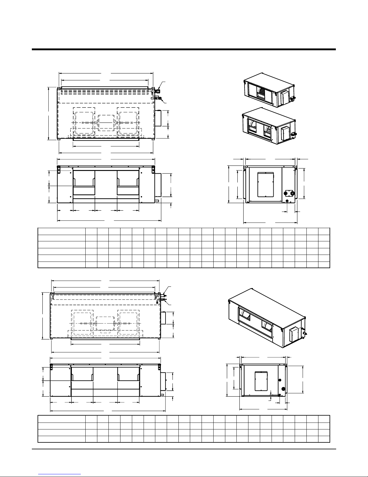
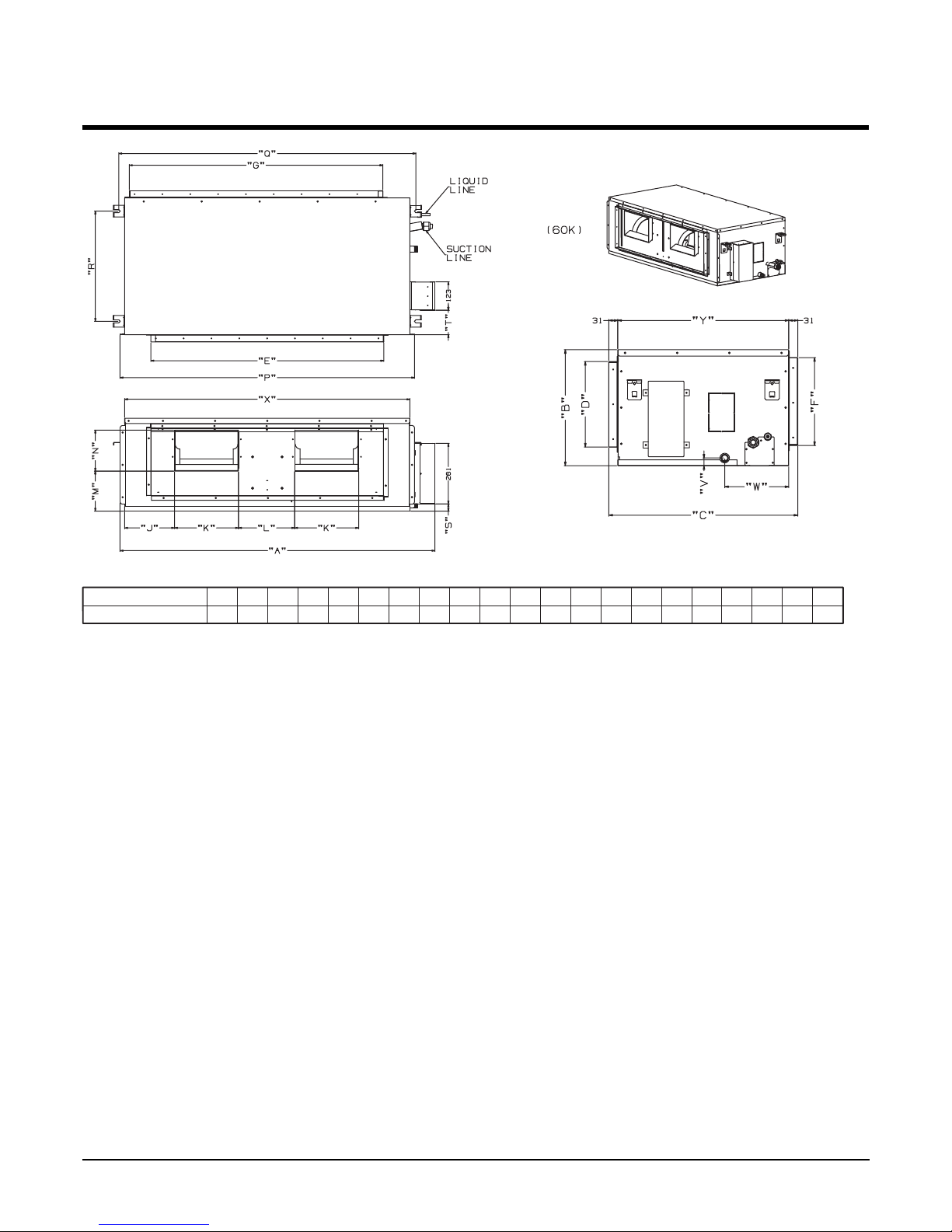
Dimension Indoor mm
Outdoor (W x H x D)
Net Indoor Kg
Weight Outdoor
Model
LB-S3061BL LB-K3660BL LB-K4260BL LB-K4880BL
1, 220-240, 50 1, 220-240, 50 1, 220-240, 50 3, 380-415, 50
7,307(2,900) 9,072(36,000) 10,584(42,000) 12,096(48,000)
8,500 10,551 12,309 14,067
3,200 3,600 5,100 4,900
8,064(32,000) 9,072(36,000) 11,314(45,500) 12,096(48,000)
9,378 10,551 13,190 14,067
3,000 3,400 4,700 4,400
14 16 22.5 8
13.5 14 21 7.3
30/26/22 35/32/28 46/38/32 49/47/44
30/26/22 35/32/28 46/38/32 49/47/44
2,020 2,240 3,600 3,351
22.6 22.6 22.6 22.6
3*3.5 3*5.5 3*8.5 4*3.5
5*1.25 5*1.25 5*1.25 5*1.25
L.C.D Wired L.C.D Wired L.C.D Wired L.C.D Wired
Orifice/Capillary Orifice/Capillary Orifice/Capillary Orifice/Capillary
Ye s Ye s Ye s Ye s
24 Hours On/Off 24 Hours On/Off 24 Hours On/Off 24 Hours On/Off
Ye s Ye s Ye s Ye s
Ye s Ye s Ye s Ye s
Ye s Ye s Ye s Ye s
Optional Optional Optional Optional
Optional Optional Optional Optional
Ye s Ye s Ye s Ye s
Optional Optional Optional Optional
Ye s Ye s Ye s Ye s
Ye s Ye s Ye s Ye s
Optional Optional Optional Optional
Ye s Ye s Ye s Ye s
Ye s Ye s Ye s Ye s
3/8(9.52) 3/8(9.52) 3/8(9.52) 3/8(9.52)
5/8(15.88) 5/8(15.88) 3/4(19.05) 3/4(19.05)
890*350*560 1,030*350*435 1,030*350*435 1,030*350*435
870*800*320 870*800*320 900*1,220*370 900*1,220*370
32 37 37 40
72 72 90 92


 User manual")


 null")