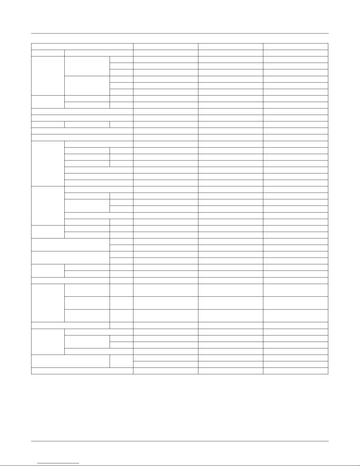
Specification
Copyright ©2014 LG Electronics. Inc. All right reserved.
Only for training and service purposes LGE Internal Use Only
- 5 -
HP
810 12 14
Model Name Combination Unit
ARUN080LSS0 ARUN100LSS0 ARUN120LSS0 ARUV140LSS0
Capacity
1)
(Rated)
Cooling
kW
22.4 28.0 33.6 38.0
kcal/h
19,300 24,100 28,900 32,700
Btu/h
76,400 95,900 114,700 129,700
Heating
kW
24.5 30.6 36.7 -
kcal/h
21,100 26,300 31,600 -
Btu/h
83,600 104,400 125,200 -
Input
(Rated)
1)
Cooling kW
6.27 8.70 10.50 11.88
Heating kW
6.28 7.56 9.66 -
EER
3.57 3.22 3.20 3.20
COP
3.90 4.05 3.80 -
Power Factor 6)
Rated -
0.93 0.93 0.93 0.93
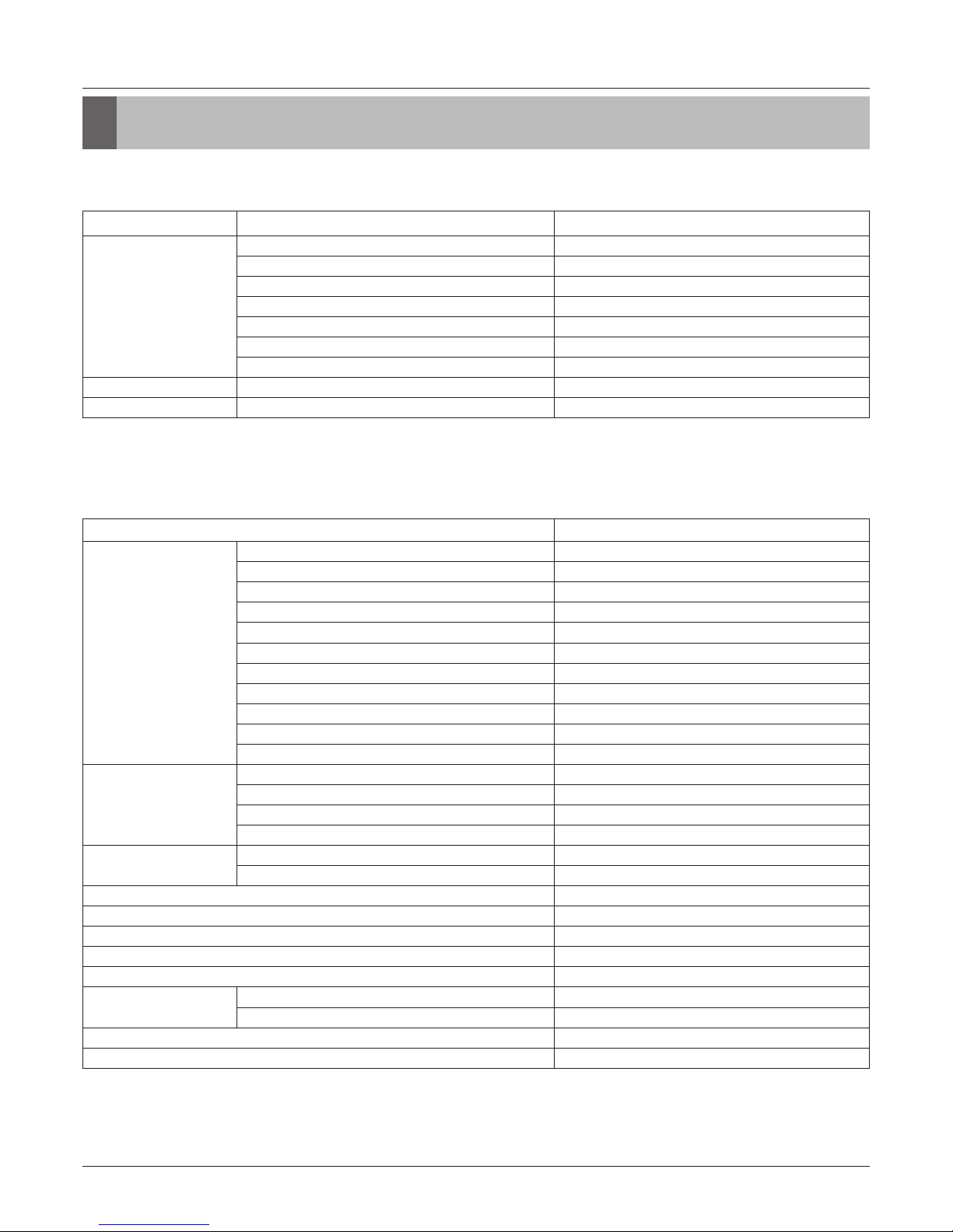
Casing Color
Warm Gray Warm Gray Warm Gray Warm Gray
Heat Exchanger
Gold fin Gold fin Gold fin Gold fin
Compressor
Type
Hermetically Sealed Scroll Hermetically Sealed Scroll Hermetically Sealed Scroll Hermetically Sealed Scroll
Piston Displacement
cm3/rev
43.8 62.1 62.1 62.1
Number of Revolution
rev/min
3,600 3,600 3,600 3,600
Motor Output
W
4,200 5,300 5,300 5,300
Starting Method
Direct On Line Direct On Line Direct On Line Direct On Line
Oil Type
FVC68D(PVE) FVC68D(PVE) FVC68D(PVE) FVC68D(PVE)
Oil Charge
2,400 2,600 3,400 3,400
Fan
Type
Propeller fan Propeller fan Propeller fan Propeller fan
Motor Output x Number
W
124 x 2 250 x 2 250 x 2 250 x 2
Air Flow
Rate(High)
m3/min
140 190 190 190
ft3/min
4,944 6,710 6,710 6,710
Drive
DC INVERTER DC INVERTER DC INVERTER DC INVERTER
Discharge
Side / Top
Side Side Side Side
Piping
Connections
Liquid mm(inch)
Ø 9.52(3/8) Ø 9.52(3/8) Ø 12.7(1/2) Ø 12.7(1/2)
Gas mm(inch)
Ø 19.05(3/4) Ø 22.2(7/8) Ø 28.58(1 1/8) Ø 28.58(1 1/8)
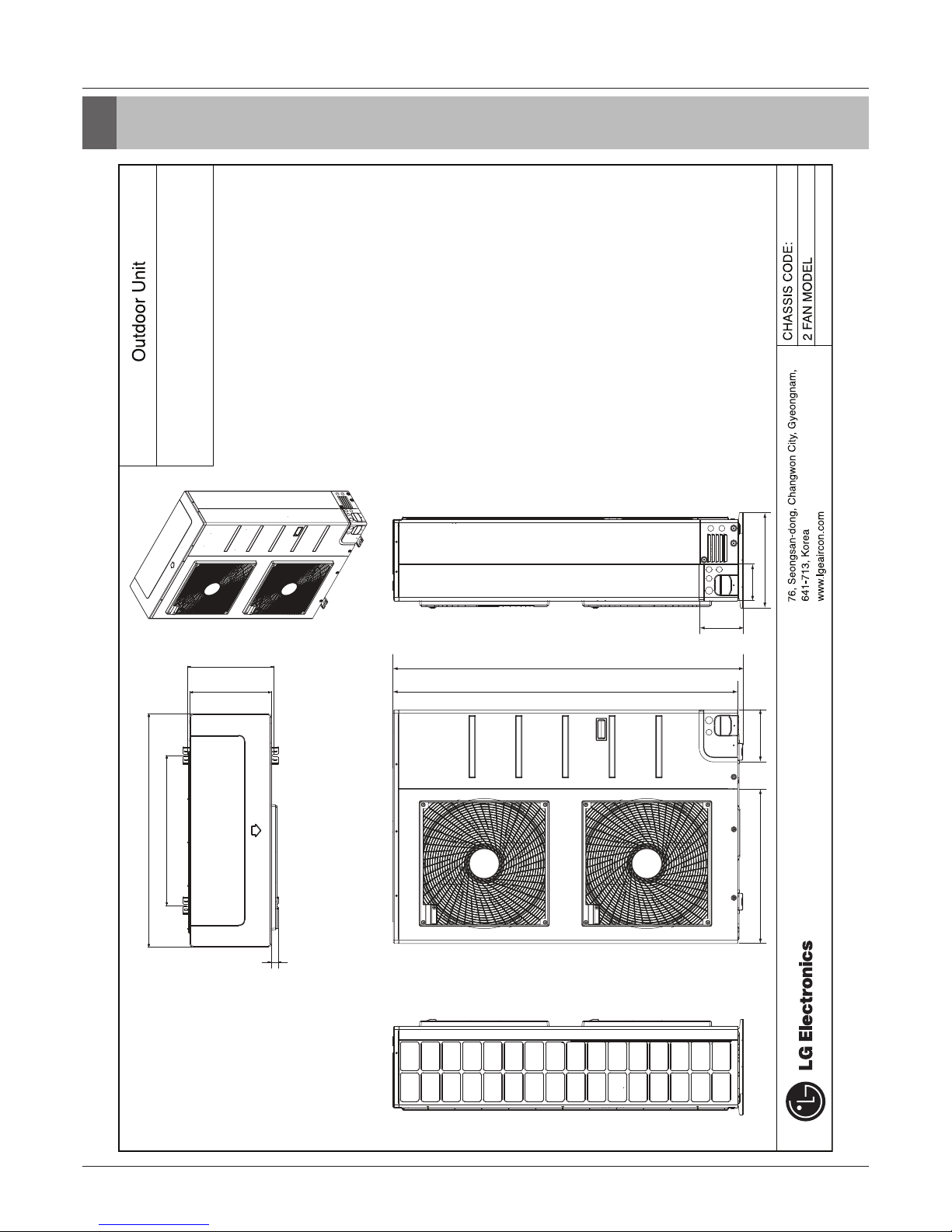
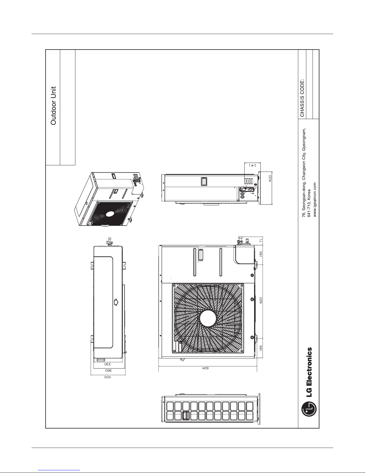
Dimensions(W x H x D) mm
950 × 1,380 × 330 1,090 × 1,625 × 380 1,090 x 1,625 x 380 1,090 x 1,625 x 380
inch
37-13/32 × 54-11/32 × 13 42-29/32 × 63-31/32 × 14-31/32 42-29/32 × 63-31/32 × 14-31/32
42-29/32 × 63-31/32 × 14-31/32
Net Weight kg
115 144 157 157
lbs
254 317 346 346
Sound Pressure
Level
Cooling dB(A)
57 58 60 61
Heating dB(A)
57 58 60 -
Sound Power Level dB(A)
69 70 71 74
Protection
Devices
High pressure
protection -
High pressure sensor /
High pressure switch
High pressure sensor /
High pressure switch
High pressure sensor /
High pressure switch
High pressure sensor /
High pressure switch
Comperssor/
Fan -
Over-heat protection /
Fan driver overload protector
Over-heat protection /
Fan driver overload protector
Over-heat protection /
Fan driver overload protector
Over-heat protection /
Fan driver overload protector
Inverter -
Over-heat protection /
Over-current protection
Over-heat protection /
Over-current protection
Over-heat protection /
Over-current protection
Over-heat protection /
Over-current protection
Communication Cable
No.xmm
2
(VCTF-SB)
2C x 1.0 ~ 1.5 2C x 1.0 ~ 1.5 2C x 1.0 ~ 1.5 2C x 1.0 ~ 1.5
Refrigerant
Refrigerant name
R410A R410A R410A R410A
Precharged
Amount
kg
3.5 4.5 6.0 6.0
lbs
7.7 9.9 13.2 13.2
Control
Electronic Expansion Valve Electronic Expansion Valve Electronic Expansion Valve Electronic Expansion Valve
Power Supply V, Ø, Hz
380-415 , 3 , 50 380-415 , 3 , 50 380-415 , 3 , 50 380-415, 3, 50
380 , 3 , 60 380 , 3 , 60 380 , 3 , 60 380, 3, 60
Number of maxmum connectable indoor units 2)
13 16 20 23
Notes:
1. Eurovent Test Condition : Maximum 4 Indoor units are connected (Indoor unit type
is only Ceiling Concealed Duct)
- Refer to EUROVENT certification regulation for more detail test conditions.
- Performances of Combination units are sum of Independent unit(Outdoor Units).
2. Performances are based on the following conditions :
- Cooling Temperature : Indoor 27°C(80.6°F) DB / 19°C(66.2°F) WB
Outdoor 35°C(95°F) DB / 24°C(75.2°F) WB
- Heating Temperature : Indoor 20°C(68°F) DB / 15°C(59°F) WB
Outdoor 7°C(44.6°F) DB / 6°C(42.8°F) WB
- Piping Length : Interconnected Pipe Length = 7.5m
- Difference Limit of Elevation (Outdoor ~ Indoor Unit) is Zero.
3. The maximum combination ratio is 160%.
4. Wiring cable size must comply with the applicable local and national codes.
5.
Due to our policy of innovation some specifications may be changed without notification.
6. Sound Level Values are measured at Anechoic chamber. Therefore, these values
can be increased owing to ambient conditions during operation.
7. Power factor could vary less than ±1% according to the operating conditions.
8. This product contains Fluorinated greenhouse gases.


 null")