LG LWHD2400HR User manual

Window-TypeAir
websit:e http:Hwww.lg_r_ice,
eomail http:://www.lge se_wice. .btml
MODELS, MODEL OS: LWHD24,_HR, LWHD18,_HR
order to=prevent
for any damages
titjoner.

FOR YOUR RECORDS
Write the mode_ and serial numbers here:
Model #
_rial #
You can find them on a _abel on the side of each un_
Dea_er's, Name
Da_e Purchased
I8[ap_e yeu_ re_ip[ to [his page i_ th,e eve_t yc_ ne_ ill
to price _te of purchase or for warranty issue,
READ THIS MANUAL
Inside you wil! find many _lp_ul hints oi_ how to use and
maintain your air conditio,_r pro_dy, Just a little pre_Jentive
care on your _t can _ y_ a great deal oi time and
me,hey _er the life of your air cond_ioner
Youll find many ans_s _o,common problems in the chart
of t_¢_b_ho_ing tips. if you review our chart el
Troubleshooting Tips first you may not _edl to call for
se_me at all,
•Coa4act the author_ service t_h_ician for repair
or maintenance of this _ni_.
•Coa4ac_ the install_ for installation of _his u_it.
•The air conditioner is _o_ lin_ended for use by young
children or invalies withou_ supervisio_
•Young children shou|_ be s_rvis_ to e_s.ure that
tlhey _o not piny with the air conditioner:
•Whe_ the power cord is _o be replaced, rep|acement
work shah be _rformed by authorized personnel only
usi#g o_ly g_uine r_lacement parts.
•|nstallatlon work mus_ be performed in _corda#ce
with the National Eie_ri.e Code [by qu_ilfi_ and
authorized pe_so_ne| o_y.
2 Room Air Conditioner

Sa_ Precautions
To prevent iniury to the user or other people and property damage, the bHiowing instructions
must be followed,
[] incorrect operation due to ignoring instruction will _us.e harm or damage. The seriousness.
is cliassifi_ by the following indications.
This sym_l indicates the possibiU_y of death or serious iniury.
This _mbo_ indic_es the po_ibili_ of injury or _ma_ to properties, only.
i Meanings of symbols us_ in this manual are as, shown below:
B,e sure not to do,
Be sure to follow the instruction,
[] Installation
,, _herwi_, _ may _u_ a fire
or eledricat sh_k,
*It may _u_ failure and
ele_ric s.ho_.
* 01therein, it may ca_ a fire
electric_ sh_k,
•Sharp edges may cau_
injuq/.
*It will _u_ electric _ or fire
due to heat generation.
• It may _u_ _p!osion or fire
Own,er_ Manual 3

!I Operation
• ]'here ='sdanger of fire or electric
shock_
• it may cau_ fire and electric
shock_
• _erwi_ it may _u_ fire and
e_tric shock a_i_nt.
• An oxygen _o.rt.age may occur,
• it will cause electric sho_ or fire
due to heat _neration
*It wiBcause failure of ma_ine or
ele#_ic sh_k_
°Otherwi_, it may electrical
shock and failure.
°Otherwise, it may cau_ a fire
or electrica_ shock,
•The appearance o_the air
condffioner may deteriorate,
change color, or deve_o.psurfa_
f_aws._
° Since the fan rotates at high
_,_d! during operation, it may
cause injury. ,.
° Prevent accident:a[ startup and
the poi_ibil_y Ofiniury:
4 Room Air Conditioner

Sa_ Precautions
• Hwill cause e_ectricshock or fire
due to heat generation,
°ff may _use eledric sh_ and
_mage
• litwill cau_ elledfic shock or fire.,
•Oth,ep,_i_, it:m_/cau_
explosion, and a fire,
•It will _ui_ e]ectric shock.
* _ey are sharp and may cause
injury,
IIn allation
• O_erwi_, it may cause dispute w_h the
neigh_rs. °O_herwi_, it may cause vibration or water
[leakage.
Own,er_ Manual 5

[] Operation
•ff my cause inju_. ,, it my cause produ_ _ai_ure. •The appearance of Me air
conditioner may,deteriorate,
change col.or,.ordevelop _rface
•lit may cau_ an injury through
dropping of the unit or fa!lling
down.,
°'_tmay cause injury.
• Operai_ionwithou_ lifters wiB
_use failure
•Other##i_ it may do harm to
your health.
° It conlains con_inmer4s and will
make you sick.
• O_henNise, ff may cause
personal injury:
6 Room Air Conditioner

BeforeOperation
1. Contact an installation specialist for installation.
2. Plug in the power plug properly:
3. Use a dedicated circuit.
4. Do not use an extension cord.
5. Do not s_rtistop operation by plugging/unplugging the _wer cord.
6. If the _rd!plug is damaged, replace it with only an authorized replacement
part.
1i. Being exposed to dir_t airflow for an extended period of time could be
hazardous to your health, Do not expose _cupants, pets, or plants to direct
airfllow for extended periods of time.
2i. Due to the _ssibilib,, of oxygen deficiency, ventilate the r_m when used
together with stoves or other heating devices,
3 Do not use this air conditioner for nonospecified special purples (e,g,
preserving precision devices, foed, pets, plants, and art objects). Such u_ge
could damage the items,
1. Do not touch the metal _rts of the unit when removing the fiiter. Injuries can
occur when handling sharp metal edges.
2. Do not use water to clean inside the air conditioner. Exposure to water can
destroy the insulation, leading to possible electric shock.
3i. When cleaning the unit, first make sure that the _wer and breaker are turned
off. The fan rotates at a very high speed during operation. There is a
_ssiibility of injury if the unit's _wer is;a_identally triggered on while
cleaning inner parts of the unit,
For repair and maintenance, contact your authorized service dealer.
Own,er_ Manual 7

introduction
This symbol alerts you to the risk of electric shock:,.
This, symbol alerts you to hazards that could cause harm to,
the air cond_ione, r.
This symbol indicates sp_ial notes.
This, appliance sho,uld _ in,stalledin accordance w_ththe National Electric C_e.
Air Di_harge
ElectricH,eate
BasePan
PowerCord
Cor_tro[Board
Evaporato_
8 Room Air Conditioner

E!_hficat Safety
! !5V~ 230V~
J
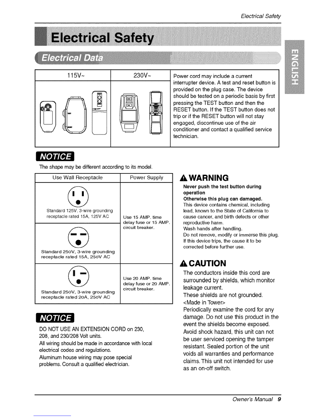
Power cord may include a current
interrupter device. A test and reset bu_on is
provided on the piug case. The dievi_
should Ibereded on a periodic basis b,yfirst
pressing the, TEST b_on and then the
RESET button, If the TEST button does not
trip or if the RESET button will not stay
engage& discontinue use of the .air
conditioner and contact a qualified service
technician.
The sha_ _y_ dif@rent _rdi_ to, its moW.
U_ Wall Receptacle Power Supply
S'_R_rd 125V, 3ow#e groundi_
receptacle rat_ 15A, 125V AC
S1:an_rd 250V, 3owire grounding
re_pt_acl!e rated 15A, 250V AC
S_ndard 250V, 3owire grounding
receptaic_e rated 20A, 250V AC
U_ 15 AMP, time
delay [u_ or 15 AMP,,
circuit breaker°
U_, _ AMP, time
de_ay fuse or :20,AMP.
circuit breaker,
DO NOT USE AN EXTENS[,ON CORD on 2_,
_8, and 230/208 Volt unRs.
AI__fing should be ma_ in _ordan_ _th I_]
e[_ri_l codes _di regulatior_,
Aluminum h_e _ring may pose s_ia[
problem& _nsu_t a q_lified ele_rician_
AWARNING
_ver push the t,e_ burton ,during
_hetwlse this plug can damaged,
Th_ d_i_ c_inrs chemi_3,L including
lead, kn_n to.the State d California to
cau_ car_er, and birth d_ts or oth_
reproductive harm.
Wash hands a_er handlhg
Do not [e.rn_e, modify _ immerse, th_ _ug.
if th_ d_k:e trips, the cau_ i_to be
corrected _fore further use.
CAUTION
The conductors inside this cord are
sur#ounded by shields, whiclh monitor
leakage currenL
These shields a_e not g[ounded,
<Made in Tower>
Periodically' examine _e cord for any
damage, Do not u_ _is product in the
event the shields, become expose.
Avoid sh_k hazard, this unit: can not
user servic_ opening the _m_r
resistant. Sealed _rflon dthe. unit
voids all warranties and! performance
c_aims, This unit not intended for use
as an on-off s_¢itch.
Own,er_ Manual 9

(PLEASE READ CAREFULLY)
FOR THE USER'S PERSONAL, SAFET'K THIS
APPLIANCE MUST" BE PROPERLY GROUNDED
The,_#er cord _ _is appliance is _uip_ w_h a
threo-prong (gr®nding} #ug,, U_ this, with a standard
thr_osl,ot (grinding} wall _er ouUet to minimize t_
h_a_d of el[ectdc sh_k. The c_lomer should have the
waft _eceptac_ and circuit choked by aqualifi_
electrician to ma_ sure the r_eptac_e is pr_dy
DO NOT CUT OR REMOVE THE THIRD (GROUND)
PRONG FROM THE P_ER PLUG.
A, SI_AT_ONS WHEN'_HE APPLIANCE Wl LL BE
DISCONNECTED OCCASIONALLY:
Because _ iPotentia_safety hazards, we strongilly
discourage the use of an adapt_ _ug_ H_ever, ff you
wish to u_ an adapter, a TEMPORARY CONNECT|ON
may _ made. Use UL4[sted adapter; availab_ frem
most ]_al hardware stores°
....[he large s]o_ in the a_pter must b_ a]kjn_ with the
large slot in the re_ptacle to assure a proper _larity
conn,ect[®.
:Attachir@_e adapte_gm,und termlnallto _e wa|!
receptacle_v_ isc_ do_ notgroundthe appliance
unless thecovetsc_ is _1, and not Insu|ated,and
_e waJ_receptacle isgroundedthroughthe house
wiring.Thecustom_ shou_ h_e the circuitchoked
aqua|_fi_ ele_ic_an to make sum_e recep_|e
is properPyg_oun_.
Di_o,nn_t '|he _er _rd from the a_,p_er,using ,one
hand _ each. Ot_m_i_, the a_pte_ ground t_mir_]
m_ht break. DO NOT USE _e ap#iance with a broken
adapter p_ugi.
_, SITUATIIONSWHEN'THE APPLIANCE WILL BE
DISCONNECTED, OFTEN.
C_ not use an ad@ter pl_ in thee, situations.
Unplugging the power oo_d frequ_tly can _ead to an
eventua_ breakage of the ground terminal The waB
power outlet should _ replaced by a thr_-sbt
(grounding) o_let in_l_ead.
USE OF' E_ENS|ON CORDS
Because _ _t_tia[ sat_y hazards, we strongly
discou/rage the use of an e×t_sion cord. H@_._er, if
yeu wish to use an extension cord, u_ a CSA
certified_JU[iisted 3-wire (grou_in,g) extensbn cord
rat_J at i5A, 125V,
10 Room Aft Co_,ditioner

tns_ltation
1/4 Bubbi!e
INSIDE
FOAM .......
CO,OLEiD,
_,,. OUTSiDE FENCE
IN'EAT
RADIATION
8
1,,To avoid vibration and no,i_, make sure the unit isinstaUed _curely and firmly.
2, In_alll the unit where the _nlight _es not shine dkectlly on the unit.
If the unit re,_ives direct sunlight, build an awning to shade Me cabinet.
3, _ere should be no ob_acle, like a fen_, wi_in 20" which might restd_ heat radiation from the con_n_r,
4,,To prevent reducing performance, inaall the unit _ that louvers of the cabinet are not Noc_ed.
5, Install the unit a little obliquely outward not _ avoid leaking Me condoned water into the room (,a_ut 1/2"
or 1/4 bubble with level).
6. InstalliMe unit with its bottom potion _~60" abo_ the fl_r level.
7,,_ufl the foam between _e top dthe unit and the wall to prevent air and insectsfrom getting into the room.
8,,The power _rd mu_ be connecCedto an inde_n_nt circuit. The green wire must be ground_.
9. Connect the drain tube to the base pan ho_ in the rear si_ if you need to drain (consult a _aler,),
Plastic hose or _uivalent may _ connected toithe drain tube.
The grille is designed to,dean the fi_er both upward and downward.
(a) (b)
A. Before attaching the front grilte to the cabin_, if _u want to puff out the fitter upward;
1. Open the inlet gdlle slightly (a).
2,,Turn insideout the front grille (a).
3. Disassemble the in_t grille from the fro,_ gnlle w_th_parating the hinged part by inserting a straight type
_rew-driver tip (b),
4. Then, rolate the inlet grille 180 degrees ,andinsert the hooks into bottom holes dthe front grille.
5,,Inert the filter and attach the front grille to the cabinet.
Boff you want to puff ,out the fitter downward;
The grille is akeady designed that w_j.
Owner_ Manual 1i

installation
All sup_ding pads should be _cured to,firm wood, masonry,
or metal
1. This unit is d_igned for installation in standard do,ubiUehung
windows with actua! o_ning widths from 29'°to 4!"
The top and bottom window _shes must open _#icienfly to
all_ adear veM_a! opening of 18" from the _ttom of the
up,per _sh to the win_w st_L
2 TInestool offer (height between the stoo! and sill),must be
I,e_ than 1 1/4,",,
iF_m strip F_mopE
(Adhesive-Backed)
Type B (h Type,C(5} Ty_ O (2)
gCarriage Bolt (2) Lock Nut (4)
12 Room Aft Conditioner

installation
SCREWDRIVER(+, -), RULER, KN|FE, HAMMER, PENCIL, LEVEL
PREPARATION OF CHASSIS
1. Remove the _rews whiich _asten the cabinet at
both _des ,andat the back,
2. Slide the unit out from the cabiinet by grippingl
the base pan handle and p,uBingb_ard while
bracing the cabinet.
3. C_ the window sash _a] to the proper length,,
Peel off the backing and ,attach the FoamoPE to
the un_rside of the window sash.
Shipping screws
Fig. 1
4..Remove the backing from Foam-PE with 3.holes
and attach itto.the _ttom o_the Top retainer
bar.
5. Attach the Top retainer bar on the top of the
cabinet w_ 3 screws (Type A)
6. In_rt the Frame guides into,the bottom of the
cabineL
7. Inert the Frame Curtain into the Top retainer bar
and Frame guides.
8. Fasten the curtains to the,unit wi_h 10 screws
(Type A) at _th sides.
Top telainer bar
Foam-PE
....Fop relaiBer bar
Screw
(Type A) Screw(Ty_ A)
Owner_ Manual 13

Installation
1. Open the window; Mark a line on the center of
the window stool be_een the _de window stop
moldings.
L_sely a_ach the sill bracket to the support
bracket using the carriage _t and the Ioicknut:,
2. Attach, the silll bracket to the window sil_using
thie_ews (Type B)..
Carefulty place the cabinet on the window stool
and align the _nter mark on the bottom front
with the center line marked window st_L
3 Using Me M-_rew and the lock nut, attach the
support bracket to the ,cabinettrack hole, Use
the first track ho.leafter the sBfbracket on Me
outer ed_ of the window aB.Tighten the
carriage bo._and the _k nut..Be sure Me
cabinet slants ou_ard,
Do not drill a hole in the _ttom pare The unff is.
designed to o_rate with approxirr_tely 1/2" o_
water in bottom pan..
4 Purl the bottom window sash down behind the,
Top relainer bar until they meet.
1, Do not pul! the window _sh down so flgNly
that the movement o_ Frame curtain is
restricted.. A_ach the _binet to the window
slool by driving the screws !_jpe B) through
the cabinet into window st_L
2..The cabinet _,ou_d I_ iinsta_d witih a very
s_ighttilt downward t_ard Me outside.
I Sill _ I
Bra Supped
,_._/ _I_J'----II III Bracket
(M-oScrew) [J,!'"
Cabinet_.
Track hole
Machi#e_rew(Typ÷D}
bck nut
sill
and bracket
Window_sh
Nretainer bar
Frame curtain
Foam PE
track
FrontAngle
14 Room Aft Co_,ditioner

installation
5, Puff each Frame curtain fulil'yto,each window _sh
track, and pull the bottom window sash _wn _hind
the Top retainer bar untJ_it meets,
6. Attach each Frame cumin the window _sh by
using screws,(Type C,) (See iFig.1O)
7, SEidethe unit into the cabinef,(See Fig 1!)
CAUTION
Forsecurity purpose, reinstall screws(Type A) at
_binet_s sides.
& C_ the Foam-strip to the proper _ength.andinsert
between the upper win_w sash and the lower
win,d{_w_sh,(See Fig 12)
& Attach the Window locking bracket with a screw
(Type C,) (See Fig, 13)
10, Attach _e 'front grille to the _binet by in_rting _e
ta_. on the griil[einto the tabs on the front of the
_binet_ Push the grille in until it snaps into
place_(See Fig,14)
11. Lift the inletgrille and secure itwffha screw (Type
A) through _e front grille°(See Fig. 14)
I2. Window in_aHati,onof room air conditioner is now
completed, See ELECTRICAL DATAfor attaching
powercord to ele_rica[ outlet.
14
15
Owner_ Manual 1_

Operating instructions
The remote contro! and con_ol panel will look #ke one of the following pictures,
1. POWER BUTTON
To _rn he air conditioner ON_pushthe button_Toturn the air _nditioner OFF,pu_ he button again_
This b_on takes prior_ overany otherbutton.
2. OPERATION MODE SELECTION BUTTON
Ever_ime you push this huron, it wil_toggle COOL, FAN and HEAT.
3, ON/OFFTiMER BU_ON
Ever_ime you push his button, timer is set as follows.(1Hour -> 2Hours _ 3Hours _ 4Hours -> 5Hours
-> 6Hours e 7Hours 4, 8Hours _ 9Hours -> lOHours _ 11Hours -> 12Hours -> Cancel)
4. FAN SPEED SELECTOR
Ever_ime you[pushh_ bu_on, it _ set as fol!o_, (Hi[ F2 ] e Low[ _:_ ] e Hi[ F2 ]' ")
5, ROOM TEMPERATURE SETTING BUTTON
This button can automatically control the tem_rature of the room. The temperature can be set within a
range of _::'F to 86_'F _ 1:'E
6. AUTO SWING
This button can automatically control the air flow direction.
7. ENERGY SAVER
_e _n _ops when the _mpre_r stops coo_ing,
&pproximately every 3 _nutes the _n_wilf turn on and ch_k the roomair to _te_ne ifcooling is need.
8, REMOCON SIGNAL RECEIVER
A slight heat odor may come _om the unit when fir_ switching to HEAT after the cooling
season is over This odor, caused by fine dust particles on the heater, wil! disappear quickly,
_d after an electrical _wer failure, the unit wi!!begin to run at its last _tting,
16 Room Air Condfioner

OperatingInstructions
When the air ,conditioner has been _ffotmed i_ c,_,lin,goper_ion and iisturned off or set to the fan
position,wait _ _east3minutes before resetting to tlhecoo_ingo_ration again,
1, Remove the _ver from the back of the remote
controller:
2, inert _vo batteries
• _ sure that the (+),and (o) directions are
c_rre_.
° _ sure that both ba_eri_, are new_
3, Re-attach the c_er,
• I_ not u_ rechargeabUe batter[_,
Such batleries differ from standard
dP/ce_ls in shape, d[men_ons, and
performance,
° Remove the batteries from the
remo_econtroller if the air
_nditioner is not going to be u_d
for an extended ]engCtho_time.
Owner_ Manual 17

OperatingInstructions
De ventilation _evermust be in the CLOSE position in order to.maintain the b_t cooling conditions,
When fresh air is n_essary in the r_m, set Me ventilation iever to the OPEN pos_ion.
The damper is opened and room air _ drawn oiuL
Before u_ng the ventilation feature,
posffio.nthe i_er, as shown. First, pull _wn
part _ to horizon_l line with part ,::i_:_
Part:
The diredio.n of air can be contro,lled wherever you
want to cool by adiusting the horizontal louver and the
vertical louver.
* HORIZO_AL AIR-DIRECTION CONTROL
To control horizontal direction of air flow, set to the
ON position the air-swing swish and the air flow will
b,e swept horizontally by the aulomatic air-swing
if you want _ stop Me air flow kom moving, _h off
the air swing s:witch at Me dedred position .of the
va he,
*VERTICAL AIR-DIRECTION CONTROL
The vertical air direction is adjusted by movingi the
horizontal _ouver.
18 Room Air Conditioner

Ope,ratingInstructions
The air conditioner employs a proper drain method whereby the condens_ 'water (moisture removed from the
air) is,drained to the ou_ide,
In very humid weather, (and for reverse cycle models in the rever_ mode) exce_,ive condensate water
removed from the air may cause _me water to co_lect To remove this excess,water you can instil the drain
pan as detai_d _]ow,
1,Take Me drain pan which is _o_ted in the air discharge
2. Remove the hol,erubber from the ba_-pan (for some m_els),.
CABINET
\
3, ]nsta!llthe drain pan to the right corner of the cabinet with 4 (or 2)
4,,Connect the drain ho_ o_3/5' insi_ diameter to the outlet I_a_di
at the bottom o_the drain pan You can purchase the drain hose or
tubing locally to satiny your part,cular needs. (Drain hose isnot
supplied),.
DRAIN
PAN
DRAIN i'°{OSE
A drain hole is,providedat the rear dthe air cond_[o,ner unit
Select a drain method according to Me fo,]lowing.,
1, Remove the hole rubber from the base-pan (for _me models)
2, Conne_ a drain ho_ of 9,/16°'ins_e diameter to Me drain pipe as
_own in Fig,.1.,
3, Or co,nn_ a p,[peelbow d9/16" [nsi_ diameter _othe drain pipe,
then connect a drain hose of 9/16" inside diame_r to the pi_
elbow as shown in Fig_2,
Own,er_ Manual 19

Maintenance and Service
TURN THE AIR CONDITIONER OFF AND REMOVE THE PLUG FROM THE POWER O'UTL_,
he air filltershould be checked at le_ twice a morr_hto see _ cleaning is ne_ssary, Trapped particles iinthe
filter will build up and bl!ockthe airflow, _is reduces the _oling _paci_ and also cauls, an accumulation of
fro,_ on the c_ling coils,,
1.Open the inlletgrille upward by pulling out the bottom of the inlet grille.(a)
In another c,ase_you _n open the inUet,gri_edownward by puUingout the top of the inlet grill!e,(b)
2,.Remove the air filter from the front gdlle assemNy by pulling the air filter upior _wn sligihtly.
3_Wash _e filter using lukewarm water below 40°C (1!O,4°F),(c)
4, Gent_'yshake the exce_ water kom the filter completely, Repla_ the filter_
(a) (b) ,(c)
Mark A of in_etgrille means opening direclJon
t. Pulll_wn front griile from _e ,cabinettop,
2 Push front grille's tips,toward the cabinet in order
_0i _a_t 'front grille's ta_, into
the cabinet,,
3,._n the inlet gril_e.
4 Tighten the screw through the front grille into the
plate of the evaporator or ba_ pan.
5,.Close,inlet gri_e_
20 Room Air Co_,ditioner
Other manuals for LWHD2400HR
1
This manual suits for next models
1
Table of contents
Other LG Air Conditioner manuals
Popular Air Conditioner manuals by other brands

Trane
Trane DC-UC-WEB01 owner's guide

Panasonic
Panasonic CS-YS9TKV operating instructions

Bard
Bard THE WALL-MOUNT WA3S3-A installation instructions

DEVOLA
DEVOLA DVCO60P user manual

Mitsubishi Electric
Mitsubishi Electric City Multi Series Technical & service manual

Frigidaire
Frigidaire FAA063P7A16 Use & care manual