LG CHASSIS PV-71A User manual

SERVICE MANUAL
LG CHASSIS PV-71A
MODEL

1
Is there about 6V
at pin 9 of P804?
YES
Is there about 11V
at '+' terminal
of C856?
YES
Is there about 6.1V
at pin 9 of IC801?
YES
Is there voltage at
pin 9 of T801?
YES
NO POWER : NO STAND-BY
Replace the Fuse
Check the 6V Line
of MAIN 1 BOARD
Check if the
Fuse is O.K.?
YES
NO
Check/Replace
D801, D802, 803, 804, R801, C807.
NO
Check/Replace
D806, Q801, R807, ZD801, C814,
IC801.
NO
¡Check/Replace FR851, D852,
C856, Q860, Q861, Q862,
ZD860, ZD861, R874.
¡Check the pin 11 of P804 :
'LOW"
NO
Check/Replace
R863, IC857, D858, R877, C875
NO
TROUBLE SHOOTING

2
Is there about 115V
at '+' terminal of C865?
YES
Is there about
6V at pin 9 of P804?
YES
NO POWER : NO MONITOR ON
Go to NO POWER (NO ST-BY)
BLOCK
Go to NO RASTER BLOCK
Check T701, Q781 and go to
NO RASTER BLOCK
Check the
NO POWER(NO ST-BY)
BLOCK
YES
NO
Check the pin 10 of P804 ; "HIGH"
NO
¡Check/Replace D851, L851,
C860, IC851.
¡Check the pin 10 of P804 :
'HIGH"
NO

3
Is there about
6.3VAC at HEATER of CPT
SOCKET?
YES
Does the waveform
appear at the collector
of Q781?
YES
Does the square
waveform appear at pin 1 of
P805?
YES
Is there about 8V
at pin 6 of P805?
YES
NO RASTER
Go to NO POWER BLOCK
Go to NO PICTURE BLOCK
Is there about 115V
at pin 3 of T701?
YES
NO
¡Check/Replace F852, D850,
C857, R899, IC853, C863.
¡Check the 8V LINE of VCD
BOARD
NO
¡Check the H-OUT LINE of VCD
BOARD.
¡Check/Replace IC501 of VCD
BOARD.
NO
Check/Replace Q782, T781, R783,
R787, Q781.
NO
Check/Replace T701, 5PIN
CONNECTOR, FR2901, FR2902
(14" : FR1901)
NO

4
Is there about
44V at pin 6 of IC701?
YES
Is there about
15V at pin 3 of
IC701?
YES
V. Deflection ERROR
Check the vertical part of VCD
BOARD
Check/Replace IC701
Does the V-A, V-B
signal appear at pin 4, 7
of P805?
YES
NO
Check/Replace FR702, D702, C704,
L731
Check;/Replace FR701, D701, C708,
L732, C734.
NO
Is there about
200V at pin 1 of P2901B?
(14" : P1901B)
YES
NO PICTURE
Check the CVBS line of VCD BOARD
(Refer to VCD BLOCK DIAGRAM)
¡Check/Replace IC2901.
(14" : IC1901)
¡Check screen voltage
Does the RGB signal
appear at pin 3, 5, 7 of
P2902? (14" : P1902)
YES
NO
Check/Replace FR704, D703, C702,
T701, 5PIN CONNECTOR, L2901,
R2924 (14" : L1901, R1924)
NO
NO

5
Does the sound
signal appear at pin 4
of IC601?
YES
Does the sound
signal appear at pin 9
of P805?
YES
NO SOUND
Check/Replace FR854, D855, IC601.
Check/Replace speaker,
speaker connector.
Is there about
25V at pin 5
of IC601?
YES
NO
Check the Audio source line of
VCD BOARD
¡Check the voltage at collector of
Q601.
¡Check/Replace IC601, external
components of IC601.
NO
NO

2-2
EXPLODED VIEW
102
913
170 150 153 511
103
112
520
501
603
604
640
650
660
601
602
620
630
610
A20
A00
P851
400 20"
400
943
943
14"
350
330
340 320
315
310
360
300
,,,,,,,,,,,,,,,,,
,,,,,,,,,,,,,,,,,
,,,,,,,,,,,,,,,,,
,,,,,,,,,,,,,,,,,
,,,,,,,,,,,,,,,,,
,,,,,,,,,,,,,,,,,
,,,,,,,,,,,,,,,,,
,,,,,,,,,,,,,,,,,
,,,,,,,,,,,,,,,,,
,,,,,,,,,,,,,,,,,
,,,,,,,,,,,,,,,,,
,,,,,,,,,,,,,,,,,
,,,,,,,,,,,,,,,,,
,,,,,,,,,,,,,,,,,
,,,,,,,,,,,,,,,,,
,,,,,,,,,,,,,,,,,
,,,,,,,,,,,,,,,,,
,,,,,,,,,,,,,,,,,
,,,,,,,,,,,,,,,,,
,,,,,,,,,,,,,,,,,
,,,,,,,,,,,,,,,,,
,,,,,,,,,,,,,,,,,
,,,,,,,,,,,,,,,,,
,,,,,,,,,,,,,,,,,
,,,,,,,,,,,,,,,,,
,,,,,,,,,,,,,,,,,
,,,,,,,,,,,,,,,,,
,,,,,,,,,,,,,,,,,
120
14"
350
120
330
340 320
315
310
360
300
20"

2-3
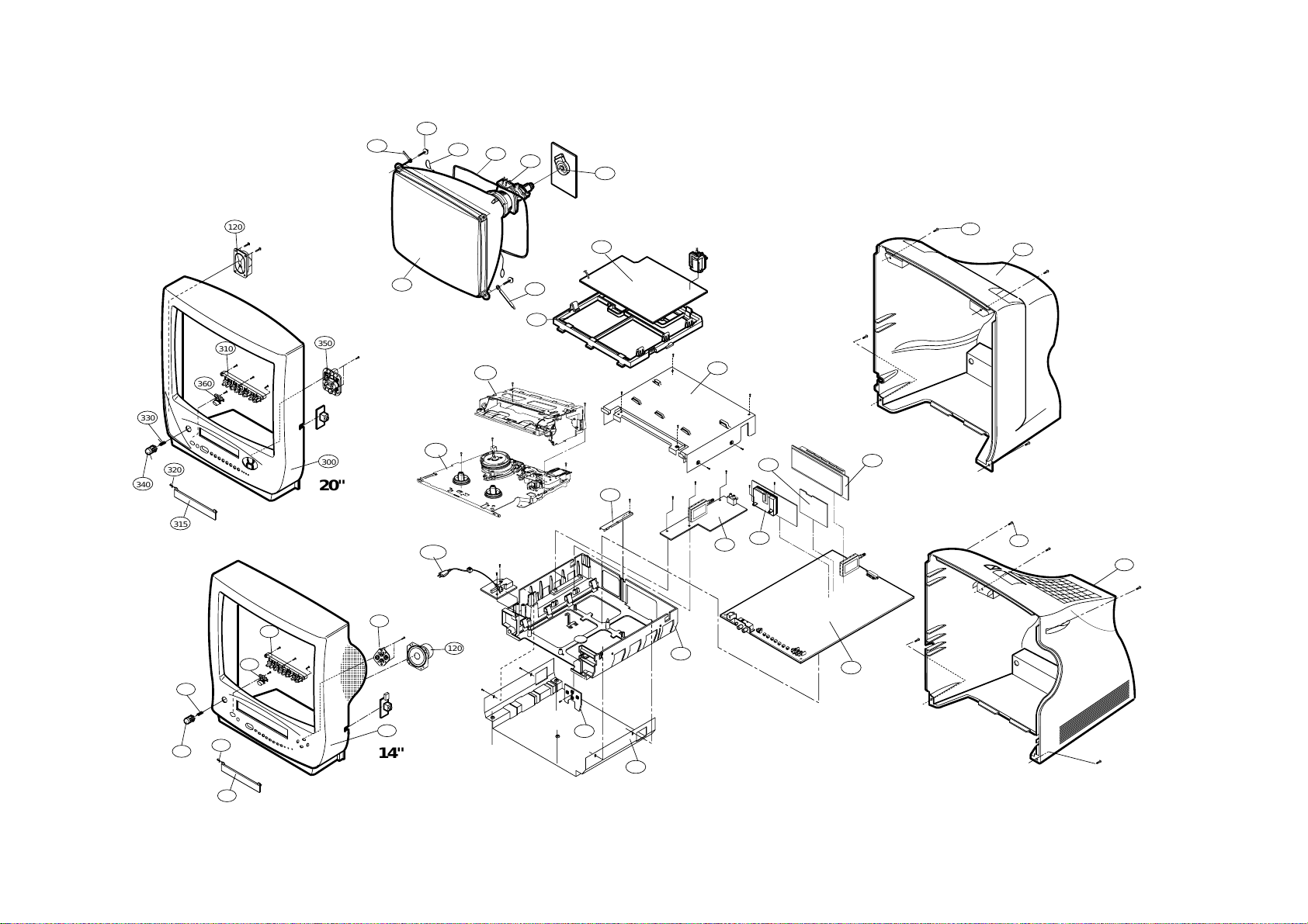
EXPLODED VIEW PART LIST The components identified by shading and
mark are critical for safety.
Replace only with part number specified.
LOCA. NO PART NO DESCRIPTIONS
102 341-721E HOLDER,D-COIL(FOR SAFA,L=65)
103 341-721F HOLDER,D-COIL(FOR SAFA,L=130)
112 2055-V1221B CPT A48QAD220X 03N7ND(+0.4) 20"
2055-V0744D CPT A34KPU02XX 31N7ND(+0.4) 14"
120 120-C93G SPEAKER,GENERAL C091P06K1459 8OHM 5/ 20"
120-101B SPEAKER,C080P17-54PK14 14"
150 150-D02M COIL,DEGAUSSING,CU 20" 60T 15OHM
150-D02B COIL,DEGAUSSING,CU 14" 42T 5.7OHM
153 153-276A DY DCAM1-20PLAA 20"
153-113V DY DCAD2-14SNAB 14"
170 170-851B LEAD SET ASSY,CPT EARTH(L=640) 20"
170-851A LEAD SET ASSY,CPT EARTH(L=460) 14"
300 3091V00057E CABINET ASSY,KI-20U72X KPLKU,LG (SILVER)
3091V00064A CABINET ASSY,KI-14U71
315 315-740H DOOR,FOR TVCR
310 5020V00118A BUTTON,CONTROL 20"
5020V00137A BUTTON,CONTROL 14"
320 4970V00001A SPRING,CST DOOR(2880)
330 320-075B SPRING,KNOB 20"
320-075R SPRING,COIL 14"
340 5020V00116A BUTTON,POWER MAIN 20"
5020V00135A BUTTON,POWER MAIN 14"
350 5020V00119A BUTTON,CH/VOL 20"
5020V00138A BUTTON,CH/VOL 14"
360 5020V00117A BUTTON,POWER SUB 20"
5020V00136A BUTTON,POWER SUB 14"
400 3809V00043E BACK COVER ASSY,KI-20U72 KPLKU
3809V00043F BACK COVER ASSY,KI-20U71 KPLKU
3809V00076E BACK COVER ASSY,KI-14U71 KPLKU
501 4810V00012A BRACKET,SMPS(27DECK)
511 6620VBC001A SOCKET,CPT 29.1 PHI SINGLE(PCS629-03A) 20"
381-100F SOCKET,CPT 022.5 S/LESS(PCS625-11) 14"
520 6871VDM027A PWB ASSY,MAIN2 PV-71A 20INCH(SMPS/CPT)
6871VDM027E PWB ASSY,MAIN2 PV-71A 20INCH(SMPS/DEF)
6871VDM027F PWB ASSY,MAIN2 PV-71A 14INCH
601 4810V00062B BRACKET,MAIN 1 ASSY SUS SPUUPRTER
602 4814V00016A SHIELD,BOTTOM
603 4814V00015A SHIELD,TOP 20"
4814V00015D SHIELD,VCR ASSY SBHG1-A 14"
604 4980V00014A SUPPORTER,YC,VCD PCB
610 6871VMM065B PWB ASSY,MAIN1, PV71A(I/I,2T,W/TXT)
6871VMM065N PWB ASSY,MAIN1, PV71A(I/I,1T,W/O TXT)
6871VMM065M PWB ASSY,MAIN1, PV71A(I/I,1T,W/TXT)
620 6871VSM094B PWB ASSY,Y/C PV71A,(W/O SECAM), M/I
630 6871VSM121B PWB ASSY,EXTRA SUB PV71A ETC (2T,B/G,I/
6871VSM121C PWB ASSY,A/V PV71A (1T,B/G,I/I)
640 6871VSM095C PWB ASSY,VCD PV71A 20" (I/I,TXT),M/I
6871VSM095F PWB ASSY,VCD PV71A 20" (I/I,W/O TXT)
6871VSM203G PWB ASSY,VCD PV71A 14" (I/I,W/O TXT)
6871VSM203A PWB ASSY,VCD/TXT 14"
650 6871VSM122B PWB ASSY,PV71A, TUNER2(I/I) ,M/I
660 6871VSM070A PWB ASSY,KEY BOARD MV-64A
913 332-057B SCREW ASSY,HEXAGON HEAD 20"
332-057A SCREW ASSY,HEXAGON HEAD 14"
943 1PPF0403116 SCREW,PAN HEAD D4 L16
A00 145-001H DECK ASSY,TV27A20P183B(6731RTV005B)
A20 146-001B HOUSING ASSY,D27S(VIDEO (219-023A))
P851 174-225E CORD ASSY,POWER UK,224A
" 174-225K CORD ASSY,POWER UK L4=100

3-5
ADJUSTMENT INSTRUCTIONS
Notes;
(Adjustments must be performed by the following procedures)
1. It is recommended that an isolation transformer be used
when servicing this chassis to prevent electric shock and
damage to test equipment.
2. The ac line voltage must be maintained at 230 vac, +- 10%,
50/60 hz.
3. Prior to making any adjustments, the receiver must be
operated for 10 minutes.
1. DECK ADJUSTMENT
1. Deck Transit System Adjustment
1-1. Necessary Instruments
1)TAPE for SP (4HD), Normal (2HD)
2)Oscilloscope
3)10:1 Probes 2EA
4)Adjustment Driver
(P2, P3, X-distance (NUT), Audio (NUT) control)
5)RMS Meter (Audio Level Meter)
1-2.Preliminary Steps
1)
Connect CH 1 of the oscilloscope to J439 (H/SW) on the
main PCB. Trigger on this channel.
2)Connect CH 2 of the oscilloscope to J218 (RF) on the main
PCB. Monitor this waveform when preceding with step 4.
3)Play an alignment tape.
4)When the "auto Trk" caption appears on screen, press the
TRK up (+) button on the RCU to initialize the manual
tracking feature.
5) If manual tracking differs from auto tracking, precede with
steps 1-3 (RF Linearity) and 1-4 (X-Distance Adj.).
1-3. RF linearity check and adjustment
1)Adjust P2 & P3 so that the RF ENVELOPE waveform is
maximum and stabilized .
2)Check if the ENVELOPE waveform is at its maximum size
by pressing TRK UP(+) and DOWN(-) button one step.
1-4. X-Distance Adjustment
1)Turn the Cone Screw of the DECK left or right so that the
RF waveform is maximum.
2)Check if the RF waveform satisfies the linearity by
pressing TRK UP(+) and DOWN(-) button one step.
CAUTION:If the RF waveform becomes maximum with
the Cone Screw more than 2 turns, its out of adjustment.
(2 turns; 720)
1-5. Audio Level Check and Adjustment
1)Connect "+" terminal of RMS Meter (Audio Level Meter)
to J233 on MAIN PCB AUDIO OUT and "-" terminal to
GND, respectively.
2)Play the 1khz and 7khz segments on the alignment tape
and confirm if the spec is meet in item #3. If not adjust
the azimuth screw to meet this spec.
3)Audio Level Spec: 1KHz ; 0.5 +_0.1Vrms
6KHz ; 1K +_1.5dB
2. CIRCUIT ADJUSTMENT
1. PG Adjustment
1-1. Necessary Instruments
1)Alignment tape SP
2)Oscilloscope
3)10 : 1 Probe
1-2.Adjustment
1)PLAY exclusive use of SP tape. (2HD: NORMAL TAPE)
2)Connect CH 1 of the Oscilloscope to J439 (H/SW) on the
MAIN PCB and VOL/DIV to 1V Range and Trigger the
Oscilloscope.
3)Connect CH 2 of the oscilloscope to J454 (Video Out) on
the main PCB and set the VOL/DIV to 500mV Range.
4)Set TIME/DIV of oscilloscope to 50us Range.
5) Adjust VR01 so that V-sync Falling Edge of Video signal
become 412usec+_20usec.
DRUM
P2
FE HEAD
P1
ARM
TENSION
P0
SUPPLY
REEL TAKE-UP
REEL
PINCH
ROLLER
TAPE
CAPSTAN
T/UP
ARM
P4
A/C
HEAD
P3 X-DISTANCE
ADJUST SCREW
AZIMUTH
SCREW CONE POINT
SCREW
A/C HEAD
HEIGHT ADJUST NUT
<Adjust Parts Location>
P2 POST ADJUST
P2
P3
P3 POST ADJUST
<Adjustment waveform>
Adjust waveform
<Adjustment Waveform>

3-6
2. Normal REC Bias Level Adjustment
2-1. Necessary Instruments
1) Blank tape for Recording
2)RMS Meter
2-2. Adjustment
1) Set the TV/VCR to A/V input mode.
2)Insert a tape and press REC button.
3)Connect RMS Meter's (+), (-) to R401 on MAIN PCB.
4)Adjust VR401 so that the RMS Meter's indicator become
within 2.6mV+_0.05mV.
3. Focus Voltage Adjustment
1)Receive the cross hatch pattern.
2)Press the PICTURE button to set the Standard ON
condition.
3)Adjust Focus control knob so that the focus of center &
circumference to be best.
4. Screen Adjustment
1)Press TV/AV button and select AV mode.
2)Adjust SCREEN control until the retrace line is visible and
return until the retrace line is invisible.
*HHHHoooowwwwttttooooggggeeeettttiiiinnnnttttooooSSSSVVVVCCCCmmmmooooddddeeeewwwwhhhheeeennnnyyyyoooouuuuddddoooonnnn''''tttthhhhaaaavvvveeeeSSSSVVVVCCCC
RRRReeeemmmmooootttteeeeCCCCoooonnnnttttrrrroooolllllllleeeerrrr....
PPPPuuuusssshhhhtttthhhheeee""""OOOOKKKK""""KKKKeeeeyyyyoooonnnntttthhhheeeeuuuusssseeeerrrr''''ssssRRRReeeemmmmooootttteeeeCCCCoooonnnnttttrrrroooolllllllleeeerrrraaaannnnddddllllooooccccaaaallll
""""OOOOKKKK""""bbbbuuuuttttttttoooonnnnaaaatttttttthhhheeeessssaaaammmmeeeettttiiiimmmmeeee....
5. VCO Adjustment
1)Select channel 0.
2) Input PAL Digital pattern (175.25MHz).
3)Press SVC Key on the Service Remote Controller to get
into SVC mode and press PR +/- Key to select VCO.
4)Press VOL +/- Key until OK is displayed on the screen.
6. LCO Adjustment
1)Select channel 99.
2) Input SECAM-L' pattern (55.75MHz).
3)Press SVC Key on the Service Remote Controller to get
into SVC mode and Press PR +/- Key to select LCO.
4)Press VOL +/- Key until OK is displayed on the screen.
7. RF AGC Adjustment
1)Input PAL DIGITAL PATTERN.
2)Connect DMM to AGC(J232) test point on the Main PCB.
3)Press SVC Key on the Service Remote Controller to get
into SVC mode and press PR +/- Key to select AGC.
4) Press VOL +/- Key until DMM reads the data on the table
below.
NNNNooootttteeee::::When adjusting 2 TUNER Model, select BOOSTER OFF
from MENU.
8. White Balance Adjustment
1)Input a signal which lower half is black and upper half is
white.
2) Set the picture at standard on.
3)Press SVC Key on the Service Remote Controller to get
into Service mode.
4)Press PR +/- Key to select BG, RG.
Press VOL +/- Key until X=281+_3, Y=288+_3.
*GG is fixed data at 32 so, do not adjust GG data.
9. Deflection Data Adjustment
1)Input PAL Digital Pattern.
2)Press SVC Key on the Service Remote Controller and
select LINE SERVICE 2 mode.
3)Press PR +/- Key to select an adjustment mode.
4) Press VOL +/- Key to adjust data.
5) Vertical SLOPE adjustment
a) Select V-SLP mode with PR +/- Key.
b) Press VOL +/- Key until the horizontal center line of
the large circle coincides with Blanking Line.
6) Vertical amplitude adjustment
a) Select V-AMP mode with PR +/- Key.
b) Press VOL +/- Key until the upper and lower end of the
large circle reach 5 mm inside from the effective area
of CPT.
7) Vertical Shift Adjustment
a) Select V-SFT mode with PR +/- Key.
b) Press VOL +/- Key until the horizontal center coincides
with the vertical sign slot mark of CPT.
8) Horizontal Shift Adjustment
a) Select H-SFT mode with PR +/- Key.
b) Press VOL +/- Key until the vertical center coincides
with the horizontal sign slot mark of CPT.
9) Vertical S-Correction Adjustment
a) Select S-COL mode with PR +/- Key.
b) Press VOL +/- Key until the grid of Cross Hatch
Pattern is even all over the screen.
Adjust Period
<Adjust Waveform>
* CAUTION:Set the trigger mode of Oscilloscope to DC.
MODEL
2 TUNER
Electric fields strength
AGC Voltage
Electric fields strength
AGC Voltage
70dBu 1dBu
5.5 0.1Vdc
65dBu 1dBu
5.6 0.1Vdc
1 TUNER
KL/KB/KI

3-2
PURITY & CONVERGENCE ADJUSTMENT
Caution:
Convergence and Purity have been factory aligned. Do not
attempt to tamper with these alignments.
However, the effects of adjacent receiver components, or
replacement of picture tube or deflection yoke may require the
need to readjust purity any convergence.
* Purity Adjustment
This procedure DOES NOT apply to bonded yoke and picture
tube assemblies.
The instrument should be at room temperature (60 degrees F or
above) for six (6) hours and be operating at low beam current
(dark background) for approximately 20 to 30 minutes before
performing purity adjustments.
CAUTION:Do not remove any trim magnets that may be
attached to the bell of the picture tube.
1. Remove the AC power and disconnect the internal
degaussing coil.
2. Remove the yoke from the neck of the picture tube.
3. If the yoke has the tape version beam bender, remove it and
replace it with a adjustable type beam bender (follow the
instructions provided with the new beam bender)
4. Replace the yoke on the picture tube neck, temporarily
remove the three (3) rubber wedges from the bell of the
picture tube and then slide the yoke completely forward.
5.Reconnect the internal degaussing coil.
6. Position the beam bender locking rings at the 9 o'clock
position and the other three pairs of tabs (2,4 and 6 pole
magnets) at the 12 o'clock position.
7. Perform the following steps, in the order given, to prepare the
receiver for the purity adjustment procedure.
a. Face the receiver in the "magnetic north" direction.
b. Externally degauss the receiver screen with the television
power turned off.
c. Turn the television on for approximately 10 seconds to
perform internal degaussing and then turn the TV off.
d. Unplug the internal degaussing coil. This allows the
thermistor to cool down while you are performing the purity
adjustment. DO NOT MOVE THE RECEIVER FROM ITS
"MAGNETIC NORTH" POSITION.
e. Turn the receiver on and obtain a red raster by increasing
the red bias control (CW) and decreasing the bias controls
for the remaining two colors (CCW).
f. Attach two round magnets on the picture tube screen at 3
o'clock and 9 o'clock positions, approximately one (1) inch
from the edge of the mask (use double-sided tape).
DEFLECTION YOKE
PURITY &CONVERGENCE
MAGNET ASSEMBLY
RUBBER
WEDGES
GLASS CLOTH TAPE
,,,,
,,,,
,,,,,
,,,,
,,,,
,,
,,
,,,
,,,
,,
,,,,,
,,,,,
,,,,,
,,,,,,
,,,,,
,,,,,
,,,,,
,,,,,
,,
PURITY MAGNET
6-POLE
4-POLE
4-POLE
MAGNET
CONVERGENCE MAGNET ASSEMBLY
6-POLE
MAGNES PURITY MAGNET(2-POLE)
X-AXIS YOKE
POSITIONING
(L/R PURITY)
6-POLE
MAGNETS
CONVERGENCE MAGNET ASSEMBLY

3-3
8. Referring to above, perform the following two steps:
a. Adjust the yoke Z-axis to obtain equal blue circles.
b. Adjust the appropriate beam bender tabs to obtain correct
purity (four equal circles).
9. After correct purity is set, tighten the yoke clamp screw and
remove the two screen magnets.
10.Remove the AC power and rotate the receiver 180 degrees
(facing "magnetic south").
11. Reconnect the internal degaussing coil.
12. Turn the receiver on for 10 seconds (make sure the receiver
came on) to perform internal degaussing, and then turn the
receiver off.
13. Unplug the internal degaussing coil.
14. Turn on the receiver and check the purity by holding one (1)
round magnet at the 3 o'clock and a second round magnet at
9 o'clock position. If purity is not satisfactory, repeat steps 8
through 14.
15. Turn off the receiver and reconnect the internal degaussing
coil.
* Convergence Adjustment
Caution:This procedure DOES NOT apply to bonded yoke and
picture tube assemblies.
Do not use screen magnets during this adjustment
procedure. Use of screen magnets will cause an
incorrect display.
1. Remove AC power and disconnect the internal degaussing
coil.
2. Apply AC Power and set the brightness to the Picture Reset
condition. Set the Color control to minimum.
3. Apply 8V to the pin.
4. Adjust the Red, Green and Blue Bias controls to get a dim
white line.
5. Remove the AC power and 8V from the pin.
6. Reconnect the internal degaussing coil and apply AC power.
7. Turn the receiver on for 10 seconds to perform internal
degaussing and then turn the receiver off again.
8. Unplug the internal degaussing-coil.
9. Turn on the receiver, connect a signal generator to the VHF
antenna terminal and apply a crosshatch signal.
Caution:During the convergence adjustment procedure, be
very careful not to disturb the purity adjustment tabs
are accidentally move, purity should be confirmed
before proceeding with the convergence adjustments.
Note:
Make sure the focus is set correctly on this instrument
before proceeding with the following adjustment.
10. Converge the red and blue vertical lines to the green vertical
line at the center of the screen by performing the following
steps (below TABLE).
a. Carefully rotate both tabs of the 4-pole ring magnet
simultaneously in opposite directions from the 12 o'clock
position to converge the red and blue vertical lines.
b. Carefully rotate both tabs of the 6-pole ring magnet
simultaneously in opposite directions form the 12 o'clock
position to converge the red and blue (now purple)
vertical lines with the green vertical line.
11. Converge the red and blue horizontal with the green line at
the center of the screen by performing the following steps.
(below TABLE)
a. Carefully rotate both tabs of the 4-pole ring magnet
simultaneously in the same direction (keep the spacing
between the two tabs the same) to converge the red and
blue horizontal lines.
b. Carefully rotate both tabs of the 6-pole ring magnet
simultaneously in same direction (keep the spacing
between the two tabs the same) to converge the red and
blue (now purple) horizontal lines with the green
horizontal line.
c. Secure the tabs previsouly adjusted by locking them in
place with the locking tabs on the beam bender.
MAGNETS
RED RED
1.ADJUST YOKE Z-AXIS FIRST
TO GET EQUAL BLUE
COLOR CIRCLES
2 .ADJUST BEAM BENDER 2 POLE
MAGNET TO GET FOUR EQUAL
COLOR CIRCLES

3-4
RING
PAIRS
4
POLE
ROTATION DIRECTION
OF BOTH TABS
OPPOSITE
SAME
OPPOSITE
SAME
MOVEMENT OF RED
AND BLUE BEAMS
B B
RR OR
OR
B R B R
OR
B
R
B
R
B R OR BR
6
POLE
12. While watching the 6 o'clock positions on the screen, rock the
front of the yoke in a vertical (up/down) direction to converge
the red and blue vertical lines. (Fig upper left)
13. Temporarily place a rubber wedge at the 12 o'clock position
to hold the vertical position or the yoke.
14.
Check the 3 o'clock and 9 o'clock areas to confirm that the red
and blue horizontal lines are converged.
If the lines are not converged, slightly offset the vertical tilt of the
yoke (move the rubber wedge if necessary) to equally balance the
convergence error of the horizontal lines at 3 o'clock and 9 o'clock
and the vertical lines at 6 o'clock and 12 o'clock.
15. Place a 1.5 inch piece of glass tape over the rubber foot at
the rear of the 12 o'clock wedge.
16. While watching the 6 o'clock and 12 o'clock areas of the
screen, rock the front of the yoke in the horizontal (left to
right) motion to converge the red and blue horizontal lines.
(Fig. upper right)
17. Temporarily place a rubber wedge at the 5 o'clock and 7
o'clock positions to hold the horizontal position of the yoke.
18. Check the 3 o'clock and 9 o'clock areas to confirm that the
red and blue vertical lines are converged. If the lines are not
converged, slightly offset the horizontal tilt of the yoke (move
the temporary rubber wedges if necessary) to equally
balance the convergence error of the horizontal lines at 6
o'clock and 12 o'clock and the vertical lines at 3 o'clock and 9
o'clock.
19. Using a round magnet confirm purity at the center, right and
left sides and corners. See Purity Adjustment Procedure.
20. Reconfirm convergence and apply a 1.5 inch piece of glass
tape over the rubber foot at the rear of the 5 o'clock and the 7
o'clock wedges.
RED
BLUE
RED BLUE
BLUE
RED
GREEN
GREEN
BLUE RED
GREEN
GREEN
ADJUSTMENT
VIEWING
AREA
UP/DOWN ROCKING OF THE YOKE
CAUSES OPPOSITE ROTATION OF RED
AND BLUE RASTERS
ADJUSTMENT
VIEWING
AREA RED
RED
GREEN
TV
SCREEN
LEET/RIGHT ROCKING OF THE YOKE
CAUSES OPPOSITE SIZE CHANGE OF
THE RED AND BLUE RASTERS
UP/DOWN ROCKING OF THE YOKE
CAUSES OPPOSITE ROTATION OF RED
AND BLUE RASTERS
LEFT/RIGHT ROCKING OF THE YOKE
CAUSES OPPOSITE SIZE CHANGE OF THE
RED AND BLUE RASTERS

4-1
FRONT LOADING MECHANISM DISASSEMBLY
¡¡
‹
Front Loading Mechanism Assembly, Parts Location
¡¡
ÿ
Component list below will be discribed as
if the top and bottom covers, front panel
and deck mechanism assembly have
already been removed.
1. Guide Cassette
2. Bracket Assembly Side (R)
3. Top Plate
4. Holder Assembly Cassette
5. Arm Assembly F/L
6. Plate Reflector
7. Opener Door
8. Plate Ground(R)
9. Plate Ground(L)
6. Plate Reflector
3. Top Plate
8. Plate Ground (R)
9. Plate Ground (L)
6. Plate
Reflector
1. Guide Cassette
4. Holder
Assembly
Cassette
2. Bracket Assembly
Side(R)
7. Opener Door
5. Arm Assembly F/L

1.Front Loading Mechanism Assembly
(Fig. A-1)
1)Remove the Top and Bottom Covers and Front Panel.
2) Remove two screws(A).
3)Lift up the Front Loading Mechanism Assembly in the
direction of arrow(B).
When disassembling and reassembling:
a.Give special attention to removal and to reassembly
because two tabs(L), (R) are engaged.
2. Guide Cassette (Fig. A-2)
1)Push tab(R) of the Cassette Guide and disengage with
Bracket Side(R) and push tab(L) of the cassette Guide
which is engaged with Bracket Side(L) and remove it in
the direction of arrow (B).
3. Bracket Assembly Side (R)
(Fig. A-3)
1)Push the tabs(L), (R) of Bracket Assembly Side(R) to
disengage with the Top Plate and remove it in the
direction of arrow(A).
4.Bracket Side(L)/Top Plate (Fig. A-4)
1)Remove the screw(B).
2)Remove the plate Ground(L), in the direction of
arrow(A).
3)Push the locking tab(L1) and then remove the Bracket
Side(L) in the direction of arrow(B).
4)The Top Plate can be removed by Separating the
Bracket Side(L).
4-2
FRONT LOADING MECHANISM DISASSEMBLY
Fig. A-1 Front Loading Mechanism
Fig. A-2 Guide Cassette
Fig. A-3 Bracket Assembly Side(R)
(A)
(C)
(B)
(B)
Hook(L)
Plate Ground(L)
Top Plate
Fig. A-4 Bracket Side(L)/Top Plate
Cassette Guide
(A)
(L)
(B)
(R)
(L)
(B)
(R)
(B)
Plate Ground
Bracket Assembly
Side(R)
Top Plate
(L)
(A)
(A)
(R)
NOTE
Brackdt Side(L)
(L1)

5.Holder Assembly Cassette (Fig. A-5)
1)Separate the Bracket Assembly Side(R).
2)Push the two lever tabs(L), (R) down and separate the
Holder Assembly Cassette and the Arm Assembly F/L
from the Top Plate.
6.Arm Assembly F/L (Fig. A-6)
1) Remove by pulling the Arm F/L(R) from the Bracket
Holder(R) Boss in the direction of arrow(A).
2)Separate the Arm Assembly F/L from Cassette Holder
Boss in the direction of arrow(B).
When disassembling and reassembling:
a. Be sure to remove the Arm F/L(R) first. If not the Arm
Assembly F/L can be damaged.
7.Spring Stopper (Fig. A-7)
1)Remove the Spring Stopper which is connected to the
tabs(A), (B) of the Lever Stopper(R) and the Bracket
Holder(R).
8.Plate Reflector (Fig. A-8)
1)Detach the Plate Reflector(L) from the Bracket Side(L)
by using a knife.
2)Detach the Plate Reflector(R) from the Bracket
Assembly Side(R) by using a knife.
4-3
Fig. A-8 Plate Reflector
Fig. A-6 Arm Assembly F/L
(B)
Arm Assembly F/L
(A)
NOTE
FRONT LOADING MECHANISM DISASSEMBLY
Plate Reflector
(L), (R)
Bracket Side(L)
Bracket
Assembly Side(R)
Spring Stopper
Lever Stopper(R)
Bracket Holder(R)
Fig. A-7
Spring Stopper
(B)
(A)
Fig. A-5 Holder Assembly Cassette
Holder
Assembly Cassette

4-4
TOP VIEW
BOTTOM VIEW
DECK MECHANISM DISASSEMBLY
*
‹
Deck Mechanism Parts Location
Auto Head Cleaner Assembly
Drum Brush
Drum Assembly
Holder
Assembly Pinch
Arm Assembly T/up
Take-up Reel
Assembly (T27)
Base Assembly
P2/P3
Tension Arm
Assembly
Supply Reel
Assembly (S27)
A/C Head Assembly
Bracket Assembly
L/D Motor
Gear Pinch Cam
TAB Lever
Plate Up
Capstan Motor
Assembly
Mode Switch
Slider Plate Bracket Cam
Clutch Assembly
S27
Arm Assembly
Idler
Gear Pulley
H1 Lever
Gear H2/H1
Clutch Assembly
T27
FE Head

1.Auto Head Cleaner Assembly (Fig. B-1)
(Optional Item)
1)Push the tab(A) of Auto Head Cleaner and remove the
Cleaner Arm Assembly.
When disassembling and reassembling:
a. Do not allow fingers or tools to touch the outside of the
Drum.
b. Be careful not to get any foreign substance on the
Roller.
2.Drum and Base Assembly (Fig. B-2)
1)Remove the Auto Head Cleaner Assembly. (option)
2)Remove three screws(A) and separate the Drum
Assembly, Drum Base and the Drum Brush from the
Deck Mechanism Assembly.
3) Remove three screws(B) on the back side and remove
the Drum Assembly from the Drum Base.
When disassembling and reassembling:
a. Do not touch the video tips with fingers or tools.
Give special attention to disassembling and
reassembling of Auto Head Cleaner Assembly.
b. After assembling, adjust the tape transport system and
Servo PG.
3.Drum Sub Assembly and Motor
Assembly (Fig. B-3-1)
1)Remove the Drum Base from the Deck Mechanism
Assembly.
2)Separate the Drum Assembly from the Drum Base.
3)Remove two screws(A) and then remove the rotor.
4)Remove three screws(B) and then remove the stator.
When disassembling and reassembling:
a. Do not touch the video tips with fingers or tools.
Fig. B
-2 Drum and Base Assembly
Fig. B
-1 Auto head cleaner Assembly
Cleaner Arm Assembly
(A)
Drum
Assembly
Drum
Base
(A)
(A)
7(A)
(B)
NOTES:
NOTES:
NOTE
DECK MECHANISM DISASSEMBLY
Drum
Brush
4-5
Fig. B
-3-1 Drum Sub and Motor Assembly
Drum
Sub Assembly
Motor
Assembly
stator
rotor
(B)
(A)

4-6
4.A/C (Audio/Control) Head Assembly
(Fig. B-4)
1)Unplug the A/C connector from the Loading Motor
P.C.B.
2)Remove two screws(A) and remove the A/C Head
Assembly from the Deck Mechanism Assembly.
When disassembling and reassembling:
a. When assembling, the 3mm hole of the Base A/C
should coincide to 3mm hole in the Chassis.
b. Do not touch the A/C Head Tips with fingers or tools.
c. After reinstalling the Audio Control Head Assembly,
adjust the Tilt, Azimuth and Height of A/C Head.
5.FE (Full Erase) Head Assembly (Fig. B-5)
(Optional Item)
1)Push two tabs(A) and remove the FE Head.
When disassembling and reassembling:
a. Be careful not to get any foreign substance on the FE
Head.
Fig. B-4 A/C Head Assembly
Fig. B-5 FE Head Assembly
(A)
NOTES:
NOTE
(A)
DECK MECHANISM DISASSEMBLY

4-7
6.Plate Up/Supply Main Brake/Take up Main
Brake/Body Prism Led Assembly (Fig. B-6)
1)Plate Up
a. Remove three screws(A) and remove the Plate Up.
2)Supply Main Brake
a. Remove the Spring MB.
b. Lift up the Supply Main Brake.
3)Take-Up Main Brake
a. Lift up the Take-Up Main Brake.
4)Body Prism Led
a. Remove the Body Prism Led.
7.Tension Arm/Lever Assembly Tension
(Fig. B-7)
1)Remove the Spring Tension.
2)Push the tab(A) of the Base Tension on the back cover
of the Deck Mechanism Assembly outward and remove
the Tension Arm Assembly.
3)Push the tab(B) on the back side of the Holder Band(A)
and remove the Tension Arm Assembly.
4)Push two tabs(C) on the bottom side of the Lever
Tension and Lift up the Lever Assembly Tension.
When disassembling and reassembling:
a. (D) is engaged to the cam groove of the Gear Cam L/D
and two tabs(C) are engaged in the chassis. (care must
be taken not to damage the two tabs when
disassembling and reassembling)
b. When disassembling, turn to the counterclockwise and
lift up so that grease which may be on (D) is not
transfered to the Reel Brake Drum.
c. When assembling, the 2.5mm hole of the Lever
Assembly Tension should be aligned with the 2.5mm
hole in the chassis.
d. After reassembling, adjust the Tension.
8. TAB Lever (Fig. B-8)
(Optional Item)
1)Remove the Lever Ass'y Tension.
2)Remove the Spring TAB.
3)Push the tab(A) on the bottom side of TAB Lever and
remove the TAB Lever.
Fig. B-6 Plate up/SMB/TMB/BPL
Fig. B-7 Tension Arm/Lever Assembly Tension
Fig. B-8 TAB Lever
(A)
(A)
(A)
TMB
Spring
MB
SMB Body
Prism Led
Plate Up
Spring TAB
TAB Lever
(A)
NOTES:
(C)
(C)
(D)
Spring Tension
Tension shaft
Chassis
Hole (2.5mm)
(A)
Lever Ass'y Tension
Holder Band (A)
Holder Band (C)
Holder Band (B)
(B)
Tension Arm
DECK MECHANISM DISASSEMBLY
Table of contents
Other LG Cell Phone manuals