LG 22XE1J User manual

2
ENGLISH
TABLE OF CONTENTS
BASIC ..........................................3
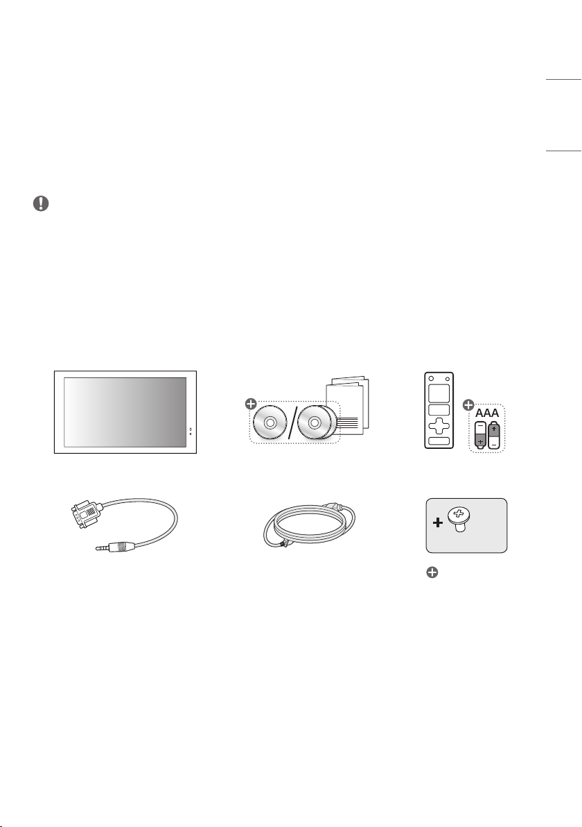
-Checking the Accessories....................................... 3
-Checking the Product Components.................. 4
GETTING READY ........................4
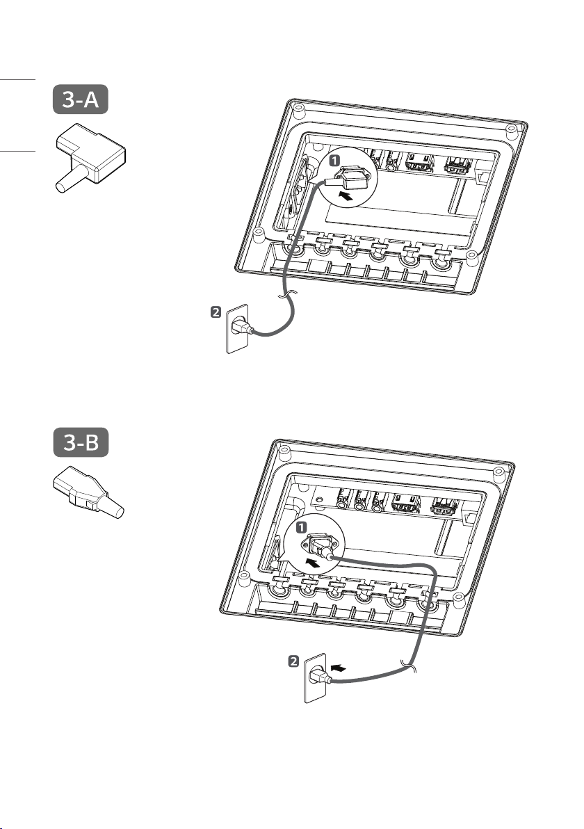
-Connecting the Cables............................................. 4
CHECKING BEFORE
INSTALLATION ........................ 10
-Installation Orientation.........................................10
-Installation Location............................................... 12
-Wall Mount Holder..................................................14
-Safety and Precaution Guide
for Installation ........................................................... 15
INSTALLING THE
PRODUCT................................. 16
-Installation Conditions.......................................... 16
-Precautions When Designing a Case ............ 17
PRECAUTIONS FOR USE......... 25
-Dust................................................................................. 25
-Afterimage................................................................... 25
PRODUCT
SPECIFICATIONS..................... 27
LICENCE................................... 30

3
ENGLISH
WARNING - This equipment is compliant with Class A of CISPR 32. In a residential environment this equipment may
cause radio interference.
BASIC
NOTE
• The accessories provided with your product may vary depending on the model or region.
• Product specifications or contents in this manual may be changed without prior notice due to upgrade of product
functions.
• SuperSign Software & Manual
-Visit
http://partner.lge.com
to download the latest SuperSign software and manual.
Checking the Accessories
X 10
(M3 x L5.5)
Depending on country

4
ENGLISH
Checking the Product Components
The illustrations may differ depending on the model.
Ambient Light Sensor / Infrared Receiver
Power
Indicator
• Ambient Light Sensor: Adjusts the screen brightness by measuring the amount of light.
• Infrared Receiver: The part that receives the signal from the remote control.
• Power Indicator: Lights up red when the screen is turned on normally. The light turns orange when in sleep mode.
GETTING READY
Connecting the Cables

5
ENGLISH
Power Cord Insertion
(Angle)
Power Cord Insertion
(Straight)
Remove the square rubbers before connecting the cables.
-7:insertpowercord(Angle)
-: insert power cord (Straight)
CAUTION
• Do not remove the square rubbers when the cables are not connected.
• If the square rubbers are not inserted without a cable, water may enter the product and cause malfunction, which is
not covered by the warranty.

6
ENGLISH
Power Cord Insertion
(Angle)
Power Cord Insertion
(Straight)

7
ENGLISH
Power Cord Insertion
(Angle)
Power Cord Insertion
(Straight)

8
ENGLISH

9
ENGLISH

10
ENGLISH
CHECKING BEFORE INSTALLATION
We are not responsible for product damage caused by failure to follow the guide.
Installation Orientation
Using Vertically
Wheninstallingvertically,rotatethemonitor90degreesclockwisewhilefacingthefrontofthescreen.
Tilt Angle
You can install the product by tilting it horizontally or vertically.
Youcantilttheproductupto15degreesforinstallation,whiletheproductshouldbespacedatleast40mmapart
from the wall.
40mm
15˚

11
ENGLISH
Ceiling, Floor Orientation
CAUTION
• Do not hang the product on the ceiling or lay it on the floor.

12
ENGLISH
Installation Location
We are not responsible for product damage caused by failure to follow the guide.
Outdoor
Installing on a Wall
• When installing the product on a wall, install a partition to separate the air from the inlet and outlet. Otherwise, the
product may malfunction, which is not covered by the warranty.
• Install a partition between the wall and the product to prevent the inlet and outlet air from mixing.
B
B
B
B
A
A:40mmormore
Installing on a Recessed Wall
Do not install the product on a recessed wall. When installing on a recessed wall, heat may cause damage to the panel
and parts, in which case it is not covered by the warranty.

13
ENGLISH
Installation of the Cased Product
• Wheninstallingaseparatecaseoutsidetheproductandinstallingitnearawall,aminimumdistanceof100mmor
more is required.
• Do not block the ventilation openings or place objects near them.
A
A:100mmormore
Installation Area
• Do not allow foreign substances such as snow to accumulate on the inlet and outlet of the product.
• The warranty will not cover any damage caused by using the product in an excessively dusty environment.

14
ENGLISH
Wall Mount Holder
To install the monitor on a wall, attach a wall mount holder (optional) to the back of the monitor.
Take caution, and ensure that the wall mount holder (optional) is securely fixed to the monitor and to the wall.
The VESA dimensions of the wall mount by model are as follows.
A
B
Model VESA Dimensions
(AxB) (mm) Standard Dimensions Length (Maximum)
(mm) Quantity
22XE1J 100x100 M4 8.5 4
CAUTION
• Disconnect the power cord first, and then move or install the monitor. Otherwise, it may result in electric shock.
• If the monitor is installed on a ceiling or inclined wall, it may fall and result in injury.
• Damage to the monitor by tightening the screws too tightly may void your warranty.
• Use screws and wall mount plates conforming to VESA standards. Breakage or personal injury due to use or misuse
of inappropriate components is not covered by the warranty of this product.
NOTE
• Using screws longer than the indicated depth may damage the inside of the product. Be sure to use the proper length.
• For more information on installation, please refer to the user manual for the wall mount.

15
ENGLISH
Safety and Precaution Guide for Installation
When Exposed to Direct Sunlight
• While powered off, make sure the device is not exposed to direct sunlight for a prolonged period.
-Protect the display with cloth or a box when storing the device after it has been powered off.
-This can prevent faults such as black spots, creases, and yellowing.
• After connecting the power, activate the [Screen Off & Backlight On (Outdoor)] feature.
-Turning the screen off can help prevent black spots, creases, yellowing, condensation, and malfunctions due to
moisture.
-For the [Screen Off & Backlight On (Outdoor)] feature, please refer to the User Guide on our homepage.
-At sub-zero temperatures, the display will be able to turn on after the internal temperature rises.
CAUTION

16
ENGLISH
INSTALLING THE PRODUCT
Installation Conditions
Inlet and Outlet Direction
• For cooling, the inlet uses a fan to draw in air and exhaust hot air to the outlet.
Air Outlet
Air Inlet
Definitions of Inlet and Outlet Terminology
Aperture Area
Aperture Size
• Aperture Size: The size of the rectangular area of the inlet
and outlet
• Aperture Area: The sum of the aperture area excluding the
grate from the aperture size
• Aperture Ratio:ApertureArea/ApertureSizex100(%)
NOTE
• Do not block the air vent of the product or place any obstacles nearby.

17
ENGLISH
Precautions When Designing a Case
• Separate the inlet and outlet with a partition.
• Place an item such as a sponge pad between the partition and the product to completely block airflow.
• Place the air vent of the case close to the air vent of the product so that the air circulates well in the product.

18
ENGLISH
Precautions on Partition Designing When Installing the Media Player
• When installing a media player as an external component, ensure it is separated from the product.
NOTE
• When applying a partition between the media player and the product, there should be no gaps other than cables.
• A media player, which is sold separately, may result in product defects by increasing the temperature inside the
product due to additional heat.
-Such defects are not covered by the warranty.
• If the partition is not applied, air from the air vent may re-enter the product through the inlet.
-In this case, the heat dissipation performance of the product may be reduced, which is not covered by the warranty.

19
ENGLISH
Inlet and Outlet Design
• Inallcases,theapertureratioofthecasemustbeatleast50%.
For Stand-Alone Installation
• Make sure to separate the inlet and outlet to prevent the air around one from entering the other.
When Drilling the Inlet and Outlet on the Back of the Case
Partition
• Aperture Size
Air Inlet 35,000mm2 or more
Air Outlet 105,000mm2 or more
Minimum Separation Distance:
60mm
125 +
mm
Product
Case

20
ENGLISH
When Drilling the Inlet and Outlet on the Side of the Case
Partition
• Aperture Size
Air Inlet 144,000mm2 or more
Air Outlet 210,000mm2 or more
Minimum Separation Distance:
200mm
265 +
mm
Product
Case
Other manuals for 22XE1J
1
Table of contents
Other LG Digital Signage manuals