LG TH900 User manual

3-2
ONE POINT REPAIR GUIDE
1. NO POWER
If the unit doesn’t work by no power problem, repair the set according to the following guide.
1-1. FUSE/ THERMISTOR/ BRIDGE DIODE
1-1-1. Solution
Please check and replace F901, TH901 or TH903, BD901 on SMPS board.
1-1-2. How to troubleshoot (Countermeasure)
1) Check if the fuse F901 is open or short-circuit.
2) Check if the NTC thermistor TH900 or TH903 is normal or open.
3) Check if the bridge diode BD901 is short-circuit by over current with a digital multi-meter.
1-1-3. Service hint (Any picture/ Remark)
< F901 >
If F901 is not short-circuit,
replace it with a same
specifications one.
< BD901 >
If BD901 is short-circuit,
replace it with a new one.
<TH901 or TH903 >
If TH901 or TH903 is open,
replace it with a new one.
jomi

3-3
ONE POINT REPAIR GUIDE
NO POWER
If the unit doesn’t work by no PVDD problem, repair the set according to the following guide.
1-2. FUSE/ FET
1-2-1. Solution
Please check and replace F901, Q901 on SMPS board.
1-2-2. How to troubleshoot (Countermeasure)
1) Check if the fuse F901 is open or short-circuit.
2) Check the anode-cathod voltage of D951 with a digital multi-meter, it is normally 0.2 ~ 0.3 V.
If it doesn’t have any voltage, it’s destroyed. Replace it with a new one.
1-2-3. Service hint (Any picture/ Remark)
< SMPS circuit >
jomi

3-4
ONE POINT REPAIR GUIDE
2. NO BOOTING WHEN POWER ON THE SET
The set doesn’t work when press the power button on the top board or the remote control.
2-1. IC501
2-1-1. Solution
Replace IC501 on MAIN board.
2-1-2. How to troubleshoot (Countermeasure)
1) Check the +12 VA (CN202) and 3.3VA (IC503) in standby mode.
If there is no 12 VA, check the SMPS and if doesn’t appear 3.3 VA, check IC503.
2) Check +12 VA, +5.1 VA, 3.3 VA, DVCC_5V and DVCC_3.3V when power on the set.
-
If the set doesn’t work regardless of what the KEY1 changes high to low while pressing the power button.
X500 and X501 work normally but, if you can not power on the set, replace the IC501 with a new one
on the main board.
2-1-3. Service hint (Any picture/ Remark)
< MAIN board top view >
< MAIN board bottom view >
X500
X500
(24 MHz)
(24 MHz)
X501
X501
(32.768 kHz)
(32.768 kHz)
KEY1
KEY1
(R518)
(R518)
PWR_CTRL
PWR_CTRL
R559
R559
jomi
3-5
ONE POINT REPAIR GUIDE
3. VFD IS NOT DISPLAYED WHEN POWER ON THE SET
When power on the set, any icons or characters on VFD are not displayed.
3-1. VFD (VFD301)
3-1-1. Solution
Please check and replace VFD301 on TOP FRONT board.
3-1-2. How to troubleshoot (Countermeasure)
1) Check if VFD_12V, DVCC_3.3V and VCC_5V are output from SMPS to VFD via the main board.
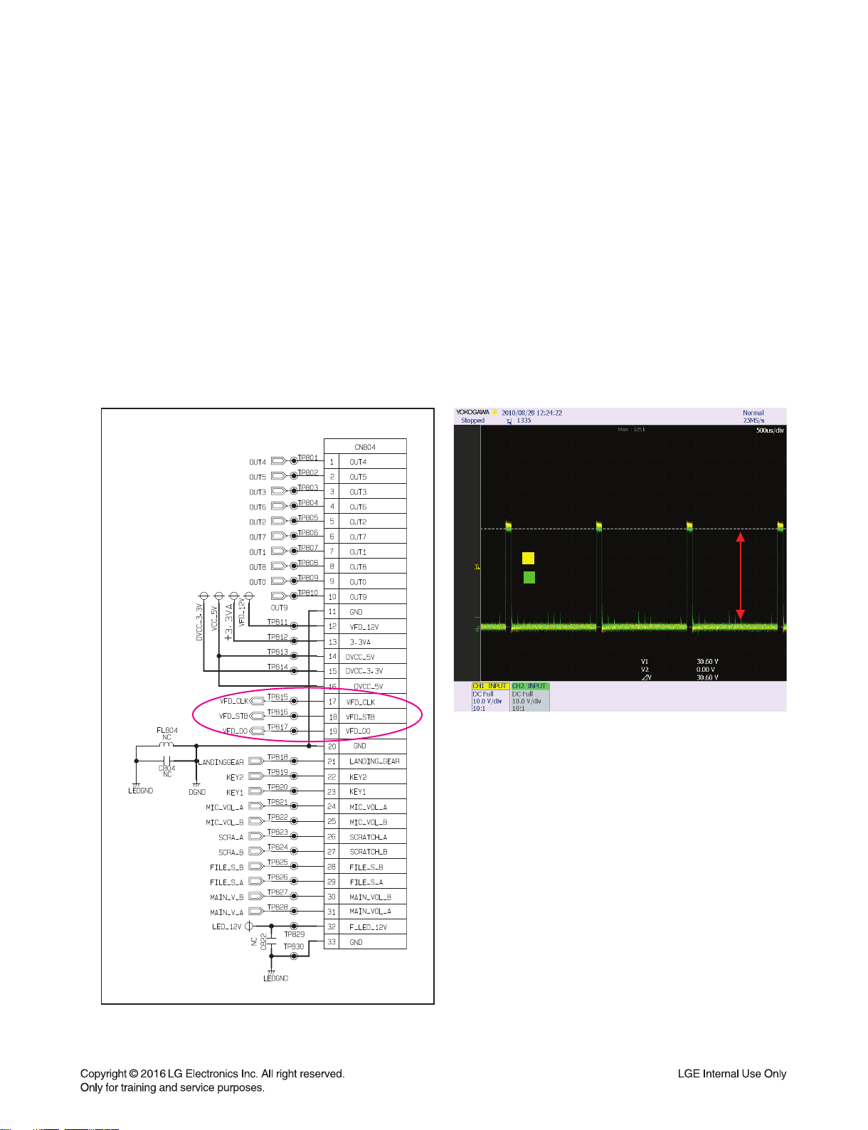
2) Check if the IC501 outputs VFD_CLK, VFD_STB, and VFD_DAT to the top board.
3) Check if the VFD grid current amplifier circuit on the top board.
Check the drive signal to the transistor’s(Q801,2) base.
If the control signals from VFD (DGND, VDD) isn’t output, replace VFD with a new one.
3-1-3. Service hint (Any picture/ Remark)
R812(TP 841)
Q801 Emitter
about
30 Vp-p
< TOP FRONT circuit >
< Waveform of the grid current driver>
jomi
3-6
ONE POINT REPAIR GUIDE
4. NO BOOTING (IN CD/USB FUNCTION)
After you turn on power key and displayed message in the following order (HELLO VOL XX
CD or USB) on VFD, it will not display other message on VFD, and it will not boot-up normally.
4-1. NO DVCC_3.3V, 1.2 VA
4-1-1. Solution
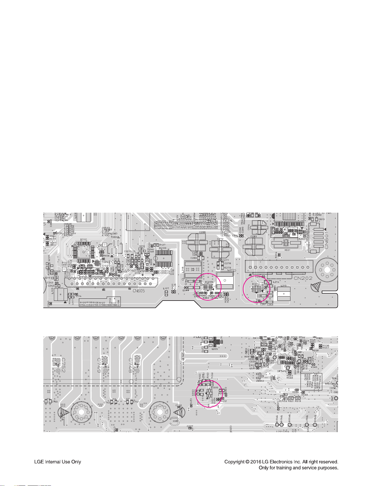
Please check and replace IC202, IC205 on MAIN board.
4-1-2. How to troubleshoot (Countermeasure)
1) Check Voltage of IC202 pin3 on MAIN board.
If IC202 pin3 (about 5.1 V) & pin1 Input 12 VA doesn’t come out, check +12 VA from SMPS board.
2) If IC202 pin3 (about 5.1 V) is normal, check voltage of IC205 pin3 (about 1.2 VA), pin6 (about 3.3 VA).
If IC205 pin3 (about 1.2 VA), pin6 (about 3.3 VA) doesn’t come out, check R253, R254, R256 and R260, R261, R262.
If there’s no defective component then replace IC205.
3) PWR_CTRL is high, check R512 and if there’s no defective component then replace IC505.
PWR_CTRL (IC505 pin3) is high (about 3.2 V)
If PWR_CTRL isn’t high, check pin D11 of IC501 & R512, R513
4) If PWR_CTRL is high, check R559 and if there’s no defective component then replace IC505.
4-1-3. Service hint (Any picture/ Remark)
< MAIN board top view >
< MAIN board bottom view >
IC505
IC505
IC202
IC202
IC205
IC205
jomi

3-7
ONE POINT REPAIR GUIDE
NO BOOTING (IN CD/USB FUNCTION)
After you turn on power key and displayed message in the following order (HELLO VOL XX
CD or USB) on VFD, it will not display other message on VFD, and it will not boot-up normally.
4-2. CRYSTAL (X500)
4-2-1. Solution
Replace X500 on MAIN board.
4-2-2. How to troubleshoot (Countermeasure)
1) If 3.3 VA & 1.2 VA is normal, check reset ‘High’ of IC501 pin T12 on MAIN board.
If MAIN_RESET isn’t high, check MICOM (IC101) pin40.
2) If MAIN_RESET is high, check the soldering status of 24 MHz crystal (X500).
3) If the crystal (X500) doesn’t oscillate, check R508, C502, C503 around crystal (X500).
If there’s no defective component, then replace X500.
4-2-3. Service hint (Any picture/ Remark)
X
XI
XO
X500
< Signal waveform >
< MAIN board top view >
IC501
IC501
X500
X500
jomi

3-8
ONE POINT REPAIR GUIDE
NO BOOTING (IN CD/USB FUNCTION)
After you turn on power key and displayed message in the following order (HELLO VOL XX
CD or USB) on VFD, it will not display other message on VFD, and it will not boot-up normally.
4-3. SERIAL FLASH (IC503)
4-3-1. Solution
Please check and replace IC503 on MAIN board.
4-3-2. How to troubleshoot (Countermeasure)
1) If the crystal (X500) does oscillate, check serial flash (IC503) on MAIN board.
Check pin8 (VCC), pin6 (CLK), pin1 (CS), pin2 (DO), pin5 (DI) of below waveform.
2) If pin1, 2, 5, 6 doesn’t come out, check registers (R563, R564, R534, R535, R536, R5E4) of IC503.
If registers of IC503 is OK, then replace IC503. (it need to download program.)
3) After change IC503, if It is still not below waveform, check IC501 (DSP IC).
4-3-3. Service hint (Any picture/ Remark)
VCC
CLK
DO
CS#
< Signal waveform >
< MAIN board bottom view >
IC503
IC503
jomi
3-9
ONE POINT REPAIR GUIDE
5. NO OPERATION OF MD
When no sound output in the CD function, you can not listen to music reading data from a CD
disc if the servo motors in MD don’t work. This step is for checking the SPINDLE MOTOR among
them.
5-1. SPINDLE MOTOR
5-1-1. Solution
Replace IC400 on MAIN board.
5-1-2. How to troubleshoot (Countermeasure)
1) Check the SPDO signal from pin16 of IC401.
If no signal, check DVCC_3.3V and DV 3.3V (RF) and X400.
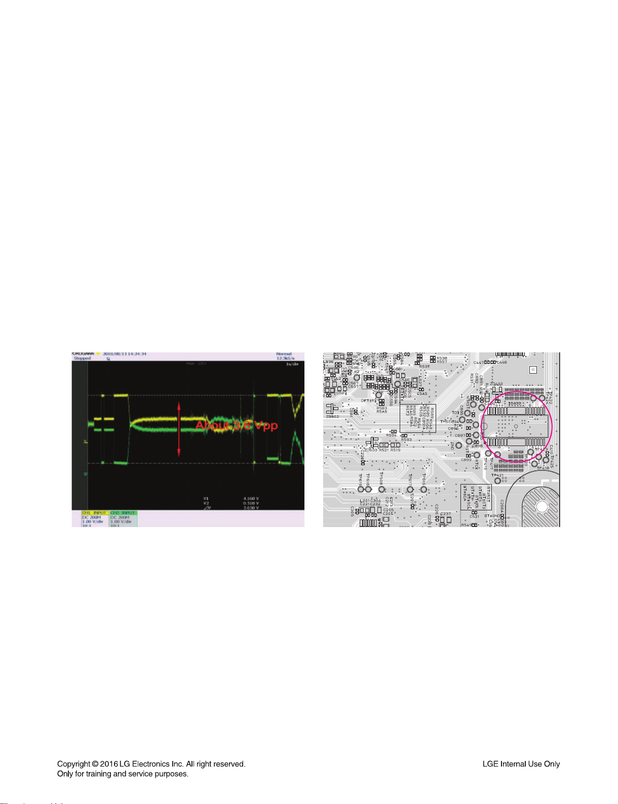
2) Check the SPIN+ & SPIN- from IC400 to CN401 for driving SPINDLE motor. It is about 3.6 Vp-p.
If no signal, check M_5 V for IC400.
3) Check if the FFC cable is solidly connected between CN401 and MD.
4) Check the MD.
If the spindle motor is sort-circuit or has any trouble, it can not rotate CD discs.
Please check the function after changing another MD.
5-1-3. Service hint (Any picture/ Remark)
< Waveform of SP- & SP+
for driving SPINDLE motor >
< MAIN board top view >
SP+: pin18
SP+: pin18
SP-: pin19
SP-: pin19
IC400
IC400
jomi

3-10
ONE POINT REPAIR GUIDE
NO OPERATION OF MD
When no sound output in the CD function, you can not listen to music reading data from a CD
disc if the servo motors in MD don’t work. This step is for checking the SLED MOTOR among
them.
5-2. SLED MOTOR
5-2-1. Solution
Replace IC400 on MAIN board.
5-2-2. How to troubleshoot (Countermeasure)
1) Check the SLDO signal from pin15 of IC401.
If no signal, check DVCC_3.3V and DV 3.3V(RF) and X400.
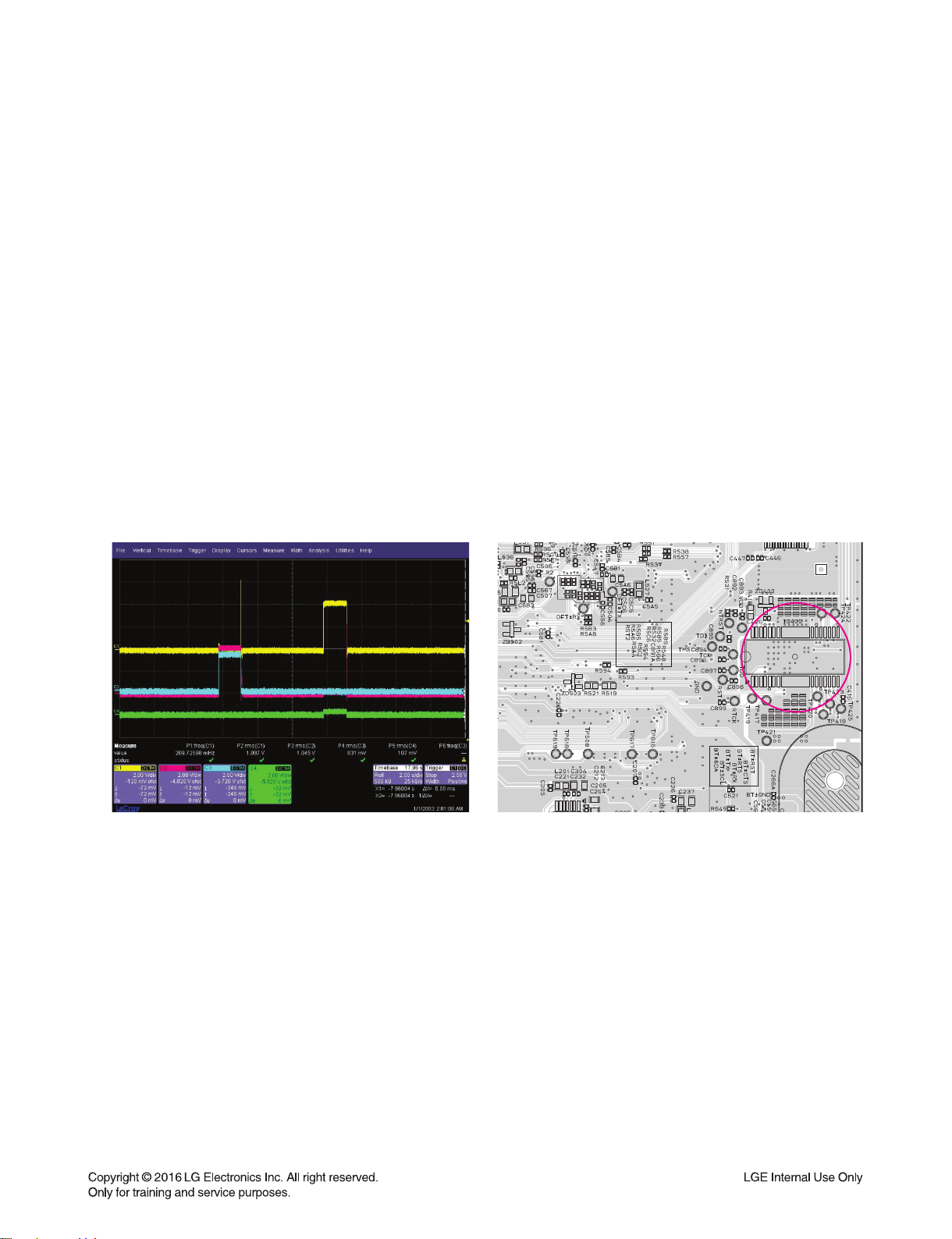
2) Check the SPED+ & SLED- from IC400 to CN401 for driving SPINDLE motor. It is about 2.9 Vp-p.
If no signal, check M_5 V for IC400.
3) Check if the FFC cable is solidly connected between CN401 and MD.
4) Check the MD.
If the spindle motor is sort-circuit or has any trouble, it can not rotate CD discs.
Please check the function after changing another MD.
5-2-3. Service hint (Any picture/ Remark)
< Waveform of SLED- & SLED+
for driving SLED motor >
SP-
SP+
< MAIN board top view >
SLED+: pin11
SLED+: pin11
SLED-: pin12
SLED-: pin12
IC400
IC400
jomi
3-11
< Waveform
for driving tray open/ close motor >
MOT_ CL OS E
MOT_ OP EN
LO+(RED)
LO-
ONE POINT REPAIR GUIDE
NO OPERATION OF MD
When no sound output in the CD function, you can not listen to music reading data from a CD
disc if the servo motors in MD don’t work. This step is for checking the TRAY OPEN / CLOSE
MOTOR among them.
5-3. TRAY OPEN/ CLOSE MOTOR
5-3-1. Solution
Replace IC400 on MAIN board.
5-3-2. How to troubleshoot (Countermeasure)
1) Check MOT_OPEN & MOT_CLOSE signals from pin P5, L4 of IC501 to IC400.
If no signal, check M_5V to IC400.
2) Check LOAD± from IC400 to CN401 for driving the tray open / close motor. It is about 3.85 Vp-p.
If no signal, check M_5V to IC400. If it has any trouble, replace it with a new one.
3) Check if the FFC cable is solidly connected between CN401 and MD.
4) Check the MD.
If the tray motor is sort-circuit or has any trouble, it can not open or close the tray.
Please check the function after changing another MD.
5-3-3. Service hint (Any picture/ Remark)
< MAIN board top view >
MOT_CLOSE: pin6
MOT_CLOSE: pin6
MOT_OPEN: pin7
MOT_OPEN: pin7
LOAD+: pin9
LOAD+: pin9
LOAD-: pin10
LOAD-: pin10
IC400
IC400
jomi
This manual suits for next models
3
Table of contents
Other LG Headset manuals

LG
LG TONE Free TONE-DFP9W User manual

LG
LG HBM-310 User manual

LG
LG TONE Free HBS-FN5W User manual

LG
LG HBS-730 User manual

LG
LG Tone Free HBS-FL7 User manual

LG
LG TONE INFINIM HBS-912 User manual

LG
LG TONE Studio HBS-W120 User manual

LG
LG Tone Infinim HBS900 User manual

LG
LG TONE Free HBS-FN4 User manual

LG
LG TONE-NP3 User manual


