LG 22LG300C User manual

담 당
관리자
Model Description
MODEL BRAND
Printing Specification
1. Trim Size (Format) : 185mm x 260 mm
2. Printing Colors
•Cover : 1 COLOR (BLACK)
•Inside : 1 COLOR (BLACK)
3. Stock (Paper)
•Cover : Coated paper, S/W 150 g/㎡
•Inside : Uncoated paper , 백상지 60 g/㎡
4. Printing Method : Off-set
5. Bindery : Perfect bind
6. Language : English (1)
7. Number of pages : 96
Part No.
1.
2.
User’s Guide Specification
Changes
4.
REV.
NO. MM/DD/YY SIGNATURE CHANGE NO. CHANGE CONTENTS
1
2
3
4
5
7
6
SUFFIX
JMJ
08.03.06
22/26/32/
37/42LG300C-ZA LG MFL34441619
(0810-REV03)
KIM JONG OK
08.03.06
(1) Origin Notification
* LGEIN : Printed in Indonesia * LGEWA : Printed in U.K.
* LGESP : Printed in Brazil * LGEMX : Printed in Mexico
* LGEND : Printed in China * LGEIL : Printed in India
* LGEMA : Printed in Poland
8
9
Special Instructions3.
Product Name
EU
10
“This part contain Eco-hazardous substances (Pb, Cd, Hg, Cr6+, PBB, PBDE, etc.) within LG standard level,
Details should be followed Eco-SCM management standard[LG(56)-A-2524].
Especially, Part should be followed and controlled the following specification.
(1)Eco-hazardous substances test report should be submitted
when Part certification test and First Mass Production.
(2) Especially, Don’t use or contain lead(Pb) and cadmium(Cd) in ink.
N
O
T
E
S
22/26/32/37/42LG300C-ZA
May.23.08 Jeon Mi Jeong S8-20892 Applied the result of PQ testing.
Sep.23.08 Jeon Mi Jeong S8-30668 Added Screw for stand fixing(37LG300C-ZA)
Oct. 21.08 Jeon Mi Jeong S8-32796 Added the Protective Bracket and Bolt for Power Cord

Pagination sheet
Pagination sheet P/NO. MFL34441619
Total pages :
96 pages
Front cover
<en>
…… …… ……
…… ……
<en>
Back cover
1……
92
Blank
page
Blank
page

Please read this manual carefully before operating
your TV.
Retain it for future reference.
Record model number and serial number of the TV.
Refer to the label on the back cover and quote this
information.
To your dealer when requiring service.
LCD TV
OWNER’S MANUAL
LCD TV MODELS
2222LL3300****
2266LL3300****
3322LL3300****
3377LL3300****
4422LL3300****
Trade Mark of the DVB Digital Video
Broadcasting Project (1991 to 1996)
ENGLISH
IIDD NNuummbbeerr((ss))::5243: 22L 300C-ZA
5242: 26L 300C-ZA
5382: 32L 300C-ZA
5383: 37L 300C-ZA
5384: 42L 300C-ZA PP//NNOO:: MMFFLL3344444411661199 ((00881100--RREEVV0033))
PPrriinntteedd iinn KKoorreeaa


1
ACCESSORIES
ACCESSORIES
Ensure that the following accessories are included with your TV If an accessory is missing, please contact the
dealer where you purchased the TV
The accessories included may differ from the images below
Batteries Remote Control
Power Cord
Polishing Cloth
Polishing cloth for use on the screen.
Lightly wipe any stains or fingerprints on the surface
of the TV with the polishing cloth.
Do not use excessive force. This may cause scratching
or discolouration.
This feature is not available for all models.
OOnnllyy 2222LL3300****
Cable Management Clip Protection Cover
OOnnllyy 2266//3322//3377//4422LL3300****
Screw for stand fixing
(Refer to P11)
Bolts for stand assembly
(Refer to P8)
x 4 x 4
Protection Cover
(Refer to P13)
or
(Only 26/32/37/42LG30**)
Owner’s Manual
Protective Bracket and Bolt for Power Cord
(This feature is not available for all models.)
(Refer to P10)
Dual Lock™
(This feature is not available for
all models.)
(Refer to P11)

ACCESSORIES
. . . . . . . . . . . . . . . . . . . . . . . . . . . . . . . . . . . . . . . . . . . . .
1
PREPARATIO
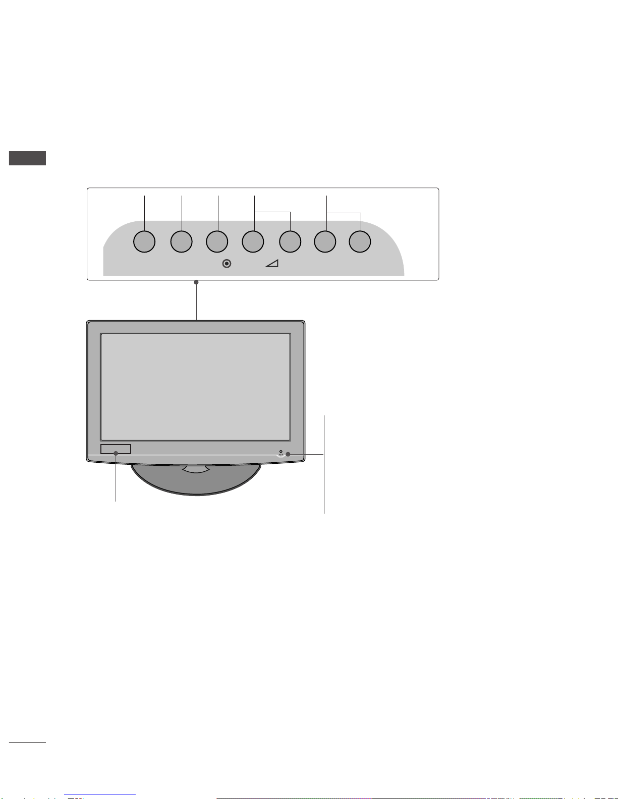
Front Panel Controls . . . . . . . . . . . . . . . . . . . . . . . . 4
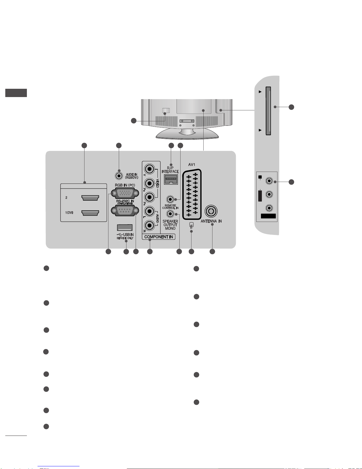
Back Panel Information . . . . . . . . . . . . . . . . . . . . . . 6
Stand Installation . . . . . . . . . . . . . . . . . . . . . . . . . . . 8
Please set it up carefully so the product
does not fall over . . . . . . . . . . . . . . . . . . . . . . . . . . . 9
Back Cover for Wire Arrangement . . . . . . . . . . . . . 10
Attaching the TV to a desk . . . . . . . . . . . . . . . . . . . 11
Swivel Stand . . . . . . . . . . . . . . . . . . . . . . . . . . . . . . . 11
Positioning your display . . . . . . . . . . . . . . . . . . . . . 12
Location . . . . . . . . . . . . . . . . . . . . . . . . . . . . . . . . . . 12
Kensington Security System . . . . . . . . . . . . . . . . . . 12
Protection cover . . . . . . . . . . . . . . . . . . . . . . . . . . . .13
Desktop Pedestal Installation . . . . . . . . . . . . . . . . . 14
Wall Mount: Horizontal installation . . . . . . . . . . . . 14
Antenna Connection . . . . . . . . . . . . . . . . . . . . . . . . 15
EXTER AL EQUIPME T SETUP
HD Receiver Setup . . . . . . . . . . . . . . . . . . . . . . . . 16
DVD Setup . . . . . . . . . . . . . . . . . . . . . . . . . . . . . . . . 18
VCR Setup . . . . . . . . . . . . . . . . . . . . . . . . . . . . . . . . 20
Other A/V Source Setup . . . . . . . . . . . . . . . . . . . . 22
Insertion of CI Module . . . . . . . . . . . . . . . . . . . . . . 22
PC Setup . . . . . . . . . . . . . . . . . . . . . . . . . . . . . . . . . 23
- Screen Setup for PC Mode . . . . . . . . . . . . . . . 26
WATCHI G TV / PROGRAMME CO TROL
Remote Control Key Functions . . . . . . . . . . . . . . . 30
Turning on the TV . . . . . . . . . . . . . . . . . . . . . . . . . . 32
Programme Selection . . . . . . . . . . . . . . . . . . . . . . . 32
Volume Adjustment . . . . . . . . . . . . . . . . . . . . . . . . . 32
On-Screen Menus Selection and Adjustment . . . . 33
Auto Programme Tuning . . . . . . . . . . . . . . . . . . . . . 34
Manual Programme Tuning (In Digital Mode) . . . . 35
Manual Programme Tuning (In Analogue Mode) . . 36
Programme Edit . . . . . . . . . . . . . . . . . . . . . . . . . . . . 38
Booster . . . . . . . . . . . . . . . . . . . . . . . . . . . . . . . . . . 41
Software Update . . . . . . . . . . . . . . . . . . . . . . . . . . . 42
Diagnostics . . . . . . . . . . . . . . . . . . . . . . . . . . . . . . . 43
CI Information . . . . . . . . . . . . . . . . . . . . . . . . . . . . . 44
Selecting the Programme Table . . . . . . . . . . . . . . 45
Input Label . . . . . . . . . . . . . . . . . . . . . . . . . . . . . . . 46
EPG (ELECTRONIC PROGRAMME
GUIDE) (IN DIGITAL MODE)
Switch On/ Off EP . . . . . . . . . . . . . . . . . . . . . . . . 47
Select Programme . . . . . . . . . . . . . . . . . . . . . . . . . . 47
Button Function in NOW/NEXT uide Mode . . . . . 47
Button Function in 8 Day uide Mode . . . . . . . . . . 48
Button Function in Date Change Mode . . . . . . . . . . 48
PICTURE CONTROL
Picture Size (Aspect Ratio) Control . . . . . . . . . . . . 49
Preset Picture Settings
- Picture Mode-Preset . . . . . . . . . . . . . . . . . . . . 51
-
Auto Colour Tone Control (Warm/Medium/Cool)
. . . . .52
Manual Picture Adjustment
- Picture Mode-User option . . . . . . . . . . . . . . . . 53
Picture Improvement Technology . . . . . . . . . . . . . . . . . 54
Advanced - Film Mode . . . . . . . . . . . . . . . . . . . . . . 55
Advanced - Black(Darkness) Level . . . . . . . . . . . . . 56
Eye Care . . . . . . . . . . . . . . . . . . . . . . . . . . . . . . . . . 57
Picture Reset . . . . . . . . . . . . . . . . . . . . . . . . . . . . . . 58
2
CO TE TS
CONTENTS

SOU D & LA GUAGE CO TROL
Auto Volume Leveler . . . . . . . . . . . . . . . . . . . . . . . . 59
Preset Sound Settings - Sound Mode . . . . . . . . . . 60
Sound Setting Adjustment - User Mode . . . . . . . . . . 61
Balance . . . . . . . . . . . . . . . . . . . . . . . . . . . . . . . . . . . 62
Audio Reset . . . . . . . . . . . . . . . . . . . . . . . . . . . . . . . 63
I/II
-
Stereo/Dual Reception (In Analogue Mode Only)
. . . . 64
-
NICAM Reception (In Analogue Mode Only) . . . . . . .
65
- Speaker Sound Output Selection . . . . . . . . . . 65
On-Screen Menu Language/Country Selection
. . . . . . . . 66
Language selection (In Digital Mode only) . . . . . . 67
TIME SETTI G
Clock Setup . . . . . . . . . . . . . . . . . . . . . . . . . . . . . . . 68
Auto On/ Off Timer Setting . . . . . . . . . . . . . . . . . . 69
Auto Shut-off Setting . . . . . . . . . . . . . . . . . . . . . . . 70
Time Zone Setup . . . . . . . . . . . . . . . . . . . . . . . . . . . 70
Sleep Timer Setting . . . . . . . . . . . . . . . . . . . . . . . . . 71
Alarm setting . . . . . . . . . . . . . . . . . . . . . . . . . . . . . . 71
PARE TAL CO TROL / RATI GS
Set Password & Lock System . . . . . . . . . . . . . . . . . 72
Block Programme . . . . . . . . . . . . . . . . . . . . . . . . . . . 73
Parental Control . . . . . . . . . . . . . . . . . . . . . . . . . . . 74
Key Lock . . . . . . . . . . . . . . . . . . . . . . . . . . . . . . . . . . 75
TELETEXT
Switch On/ Off . . . . . . . . . . . . . . . . . . . . . . . . . . . . 76
SIMPLE Text . . . . . . . . . . . . . . . . . . . . . . . . . . . . . . . 76
TOP Text . . . . . . . . . . . . . . . . . . . . . . . . . . . . . . . . . 76
FASTEXT . . . . . . . . . . . . . . . . . . . . . . . . . . . . . . . . . 77
Special Teletext Functions . . . . . . . . . . . . . . . . . . . . 77
DIGITAL TELETEXT
Teletext within Digital Service . . . . . . . . . . . . . . . 78
Teletext in Digital Service . . . . . . . . . . . . . . . . . . 78
APPE DIX
Initializing (Reset to original factory setting) . . . . . 79
Troubleshooting . . . . . . . . . . . . . . . . . . . . . . . . . . . 80
Maintenance . . . . . . . . . . . . . . . . . . . . . . . . . . . . . . 82
Product Specifications . . . . . . . . . . . . . . . . . . . . . . 83
IR Codes . . . . . . . . . . . . . . . . . . . . . . . . . . . . . . . . . 84
External Control Device Setup . . . . . . . . . . . . . . . 86
3
CONTENTS

4
PREPARATIO
PREPARATION
FRONT PANEL CONTROLS
■
Image shown may differ from your TV.
■
If your TV has a protection film attached, remove the film and then wipe the TV with a polishing cloth.
INPUT MENU P-+-+OK
PROGRAMMEVOLUME
MENU OK
INPUT
22LG30**
POWER
Remote Control Sensor
Power/Standby Indicator
• illuminates red in standby mode.
• illuminates blue when the TV is switched on.
Note: You can adjust PPoowweerr IInnddiiccaattoorrin the OPTION
menu.
Clock LED

5
PREPARATION
26/32/37/42LG30**
POWER
Remote Control Sensor
Power/Standby Indicator
• illuminates red in standby mode.
• illuminates blue when the TV is switched on.
Note: You can adjust PPoowweerr IInnddiiccaattoorrin
the OPTION menu.
P
MENU
INPUT
OK
+
-
+
-
PROGRAMME
VOLUME
OK
MENU
INPUT
Clock LED

BACK PANEL INFORMATION
A
Image shown may differ from your TV.
6
PREPARATION
PREPARATION
AV IN 2
L/ MONO
R
AUDIO
PCMCIA CARD SLOT
VIDEO
( )
HDMI/DVI IN
2 3 4 5
AV IN 2V IN 2
L/MONOMONO
R
AUDIOAUDIO PCMCIA CARD SLOTPCMCIA CARD SLOT
VIDEOVIDEO
( )
HDMI/DVI IN
121186 7910
13
14
22LG30**
1
Power Cord Socket
This TV operates on an AC power. The voltage is
indicated on the Specifications page. Never
attempt to operate the TV on DC power.
HDMI Input
Connect a HDMI signal to HDMI IN. Or DVI (VIDEO)
signal to HDMI/DVI port with DVI to HDMI cable.
RGB/DVI Audio Input
Connect the audio from a PC or STB with DVI output.
RJP INTERFACE
Connect control line (RJ45) for RJP(Remote Jack pack)
Remote Control Port
RGB Input
Connect the output from a PC.
SERVICE ONLY PORT
RS-232C IN (CONTROL & SERVICE) PORT
Connect to the RS-232C port on a PC.
Component Input
Connect a component video/audio input to these
jacks.
SPEAKER OUTPUT(MONO)
The phone socket for external speaker is on this
jack.
Euro Scart Socket (AV1)
Connect scart socket from an external device to
this jack.
Antenna Input
Connect RF antenna to this jack.
PCMCIA (Personal Computer Memory Card
International Association) Card Slot
(This feature is not available in all countries.)
Audio/Video Input(AV2)
Connect audio/video output from an external
device to these jacks.
1
2
3
4
5
6
7
8
9
10
11
12
13
14

7
PREPARATION
26/32/37/42LG30**
AV IN 2
L/ MONO
R
AUDIO
PCMCIA CARD SLOT
VIDEO
( )
2 3 4 5
AV IN 2V IN 2
L/MONOMONO
R
AUDIOAUDIO PCMCIA CARD SLOTPCMCIA CARD SLOT
VIDEOVIDEO
( )
121186 7910
13
14
1
Power Cord Socket
This TV operates on an AC power. The voltage is
indicated on the Specifications page. Never
attempt to operate the TV on DC power.
HDMI Input
Connect a HDMI signal to HDMI IN. Or DVI (VIDEO)
signal to HDMI/DVI port with DVI to HDMI cable.
RGB/DVI Audio Input
Connect the audio from a PC or STB with DVI output.
RJP INTERFACE
Connect control line (RJ45) for RJP(Remote Jack pack)
Remote Control Port
RGB Input
Connect the output from a PC.
SERVICE ONLY PORT
RS-232C IN (CONTROL & SERVICE) PORT
Connect to the RS-232C port on a PC.
Component Input
Connect a component video/audio input to these
jacks.
SPEAKER OUTPUT(MONO)
The phone socket for external speaker is on this
jack.
Euro Scart Socket (AV1)
Connect scart socket from an external device to
this jack.
Antenna Input
Connect RF antenna to this jack.
PCMCIA (Personal Computer Memory Card
International Association) Card Slot
(This feature is not available in all countries.)
Audio/Video Input(AV2)
Connect audio/video output from an external
device to these jacks.
1
2
3
4
5
6
7
8
9
10
11
12
13
14

8
PREPARATION
Stand installation
A
Image shown may differ from your TV.
Assemble the parts of the SSTTAANNDD BBOODDYYwith
CCOOVVEERR BBAASSEEof the TV. Insert the SSTTAANNDD
BBOODDYYinto a CCOOVVEERR BBAASSEEuntil clicking sound.
2
Assemble the TV as shown.
3
For 22LG30** For 26/32/37/42LG30**
SSTTAANNDD BBOODDYY
CCOOVVEERR BBAASSEE
Carefully place the TV screen side down on a
cushioned surface to protect the screen from
damage.
1
Assemble the parts of the SSTTAANNDD BBOODDYY
with CCOOVVEERR BBAASSEEof the TV.
2
Assemble the TV as shown.
3
Fix the 4 bolts securely using the holes in the
back of the TV.
4
SSTTAANNDD BBOODDYY
CCOOVVEERR BBAASSEE
Carefully place the TV screen side down on a
cushioned surface to protect the screen from
damage.
1

9
PREPARATION
PLEASE SET IT UP CAREFULLY SO THE PRODUCT DOES NOT
FALL OVER
■You should purchase necessary components to fix the TV to the wall on the market
■Position the TV close to the wall to avoid the possibility of it falling when pushed.
■The instructions shown below are a safer way to set up the TV, which is to fix it to the wall, avoiding the
possibility of it falling forwards if pulled. This will prevent the TV from falling forward and causing injury. This
will also prevent the TV from damage. Ensure that children do not climb or hang from the TV.
OTE
!
G When moving the TV undo the cords first
G Use a platform or cabinet strong and large enough to support the size and weight of the TV
G To use the TV safely make sure that the height of the bracket on the wall and on the TV is the same
3
1
2
Use the eye-bolts or TV brackets/bolts to fix the TV to the wall as shown in the picture.
(If your TV has bolts in the eyebolts, loosen these bolts.)
* Insert the eye-bolts or TV brackets/bolts and tighten them securely in the upper holes.
Secure the wall brackets with the bolts on the wall. Match the height of the bracket that is mounted on the
wall.
3Use a sturdy rope to tie the TV. It is safer to tie the rope so it becomes horizontal between the wall and the
TV.
2
1

10
PREPARATION
PREPARATION
BACK COVER FOR WIRE ARRANGEMENT
A
Image shown may differ from your TV.
Connect the cables as necessary.
To connect additional equipment, see the
EXTER AL EQUIPME T SETUP section.
Secure the power cable with the PROTECTIVE
BRACKET and the screw as shown. It will help prevent
the power cable from being removed by accident.
Install the CABLE MA AGEME T CLIP as shown.
1
2
Fit the CABLE MA AGEME T CLIP as shown.
3
Connect the cables as necessary.
To connect additional equipment, see the
EXTER AL EQUIPME T SETUP section.
Secure the power cable with the PROTECTIVE
BRACKET and the screw as shown. It will help prevent
the power cable from being removed by accident.
Install the CABLE MA AGEME T CLIP as
shown.
1
2
Put the cables inside the CABLE MA AGEME T
CLIP and snap it closed.
3
For 26/32/37/42LG30**
For 22LG30**
GGDo not hold the CABLE MA AGEME T CLIP when moving the TV.
- If the TV is dropped, you may be injured or the product may be broken.
OTE
!
GGHold the CABLE MA AGE-
ME T CLIP with both hands
and pull it backward.
How to remove the
CABLE MA AGEME T CLIP
PROTECTIVE
BRACKET
(This feature is not
available for all models.)
PROTECTIVE
BRACKET
(This feature is not
available for all models.)
CABLE MA AGEME T CLIP

11
PREPARATION
Attaching the TV to a desk (Only 26/32/37/42LG30**)
WAR I G
!
GG To prevent TV from falling over, the TV should be securely attached to the floor/wall per installation
instructions Tipping, shaking, or rocking the machine may cause injury
The TV must be attached to desk so it cannot be pulled in a forward/backward direction, potentially causing
injury or damaging the product. Use only an attached screw.
1-Screw
(provided as parts of the product)
Desk
Stand
Swivel Stand (Only 26/32/37/42LG30**)
After installing the TV, you can adjust the TV manually
to the left or right direction by 20 degrees to suit your
viewing position.
How to use Dual Lock™ (This feature is not available for all models )
Fix the set-top box to the TV and use it when you want to.
After removing the protection paper from
the Dual Lock, stick it to the TV and the
set-top box as shown
Attach the set-top box to the TV by pressing
the Velcro strips together.
1
2

12
PREPARATION
PREPARATION
POSITIONING YOUR DISPLAY
(Only 22LG30**)
■Image shown may differ from your TV.
■Adjust the position of the panel in various ways for
maximum comfort.
• Tilt range
LOCATION
(Only 22LG30**)
Position your TV so that no bright light or sunlight falls directly onto the screen. Care should be taken not to
expose the tv to any unnecessary vibration, moisture, dust or heat. Also ensure that the TV is placed in a position
to allow a free flow of air. Do not cover the ventilation openings on the back cover.
If you intend to mount the TV to a wall, attach VESA standard mounting interface (optional parts) to the back of
the TV.
When you install the TV to use the wall mounting bracket (optional parts), fix it carefully so as not to drop.
KENSINGTON SECURITY SYSTEM (Only 22LG30**)
The TV is equipped with a Kensington Security System connector on the back panel. Connect the Kensington
Security System cable as shown below.
For the detailed installation and use of the Kensington Security System, refer to the user’s guide provided with
the Kensington Security System.
For further information, contact http://www kensington com, the internet homepage of the Kensington
company. Kensington sells security systems for expensive electronic equipment such as notebook PCs and LCD
projectors.
NOTE
- The Kensington Security System is an optional accessory.
NOTES
a. If the TV feels cold to the touch, there may be a small “flicker” when
when it is turned on.
This is normal, there is nothing wrong with TV.
b. Some minute dot defects may be visible on the screen, appearing as
tiny red, green, or blue spots. However, they have no adverse effect on
the monitor's performance.
c. Avoid touching the LCD screen or holding your finger(s)
against it for long periods of time.
Doing so may produce some temporary distortion effects on the screen.
12
0
3
0

13
PREPARATION
PROTECTION COVER
For 22LG30** For 26/32/37/42LG30**
HHIINNEE BBOODDYY
■
Image shown may differ from your TV.
When installing the wall-mounted unit, use the pro-
tection cover for desk-type stand installation. Insert
the PPRROOTTEECCTTIIOONN CCOOVVEERRinto the TV until click-
ing sound.
Loose the bolts from TV.
1
Insert the PPRROOTTEECCTTIIOONN CCOOVVEERRinto the TV.
3
PPRROOTTEECCTTIIOONN CCOOVVEERR
Bend the HHIINNEE BBOODDYYand pull it backward.
2
Fix the 4 bolts securely using the holes in the
back of the TV.
4
or

14
PREPARATION
DESKTOP PEDESTAL I STALLATIO
For adequate ventilation allow a clearance of 4” (10cm) all around the TV.
EARTHI G
Ensure that you connect the earth wire to prevent possible
electric shock. If grounding methods are not possible, have a
qualified electrician install a separate circuit breaker.
Do not try to earth the TV by connecting it to telephone
wires, lightening rods or gas pipes.
Power Supply
Circuit
breaker
■The TV can be installed in various ways such as on a wall, or on a desktop etc
■The TV is designed to be mounted horizontally
4 inches
4 inches 4 inches 4 inches
WALL MOU T: HORIZO TAL I STALLATIO
For adequate ventilation allow a clearance of 4” (10cm) all around the TV. We recommend that you
use a wall mounting bracket of LG brand when mounting the TV to a wall
4 inches
4 inches
4 inches 4 inches
4 inches

AV IN 2
L/ MONO
R
AUDIO
PCMCIA CARD SLOT
VIDEO
( )
HDMI/DVI IN
AV IN 2
L/ MONO
R
AUDIO
PCMCIA CARD SLOT
VIDEO
( )
HDMI/DVI IN
15
PREPARATION
■For optimum picture quality, adjust antenna direction.
■An antenna cable and converter are not supplied.
Multi-family Dwellings/Apartments
(Connect to wall antenna socket)
Single-family Dwellings /Houses
(Connect to wall jack for outdoor antenna)
Outdoor
Antenna
(VHF, UHF)
Wall
Antenna
Socket
RF Coaxial Wire (75 ohm)
ANTENNA CONNECTION
Antenna
UHF
Signal
Amplifier
VHF
■In poor signal areas, to achieve better picture quality it may be necessary to install a signal amplifier to the
antenna as shown above.
■If signal needs to be split for two TVs, use an antenna signal splitter for connection.
■To prevent damage do not connect to the mains outlet until all connections are made between the devices.

16
EXTER AL EQUIPME T SETUP
PREPARATION
Connect the video outputs (Y, PB, PR)of the digital set
top box to the CCOOMMPPOONNEENNTT IINN VVIIDDEEOOjacks on the TV.
Connect the audio output of the digital set-top box to
the CCOOMMPPOONNEENNTT IINN AAUUDDIIOOjacks on the TV.
Turn on the digital set-top box.
(Refer to the owner’s manual for the digital set-top box.)
Select CCoommppoonneennttinput source using the IINNPPUUTTbutton
on the remote control.
2
3
4
1
HD RECEIVER SETUP
■To avoid damaging any equipment, never plug in any power cords until you have finished connecting all equipment
■This section on EXTERNAL EQUIPMENT SETUP mainly uses diagrams for the 26LG30
**
models
Connecting with a component cable
HDMI/DVI IN
12
Signal
480i/576i
480p/576p
720p/1080i
1080 p
Component
Yes
Yes
Yes
Yes
HDMI
No
Yes
Yes
Yes
■This TV can receive Digital RF/Cable signals without an external digital set-top box. However, if you do receive
Digital signals from a digital set-top box or other digital external device, refer to the diagram as shown below.
This manual suits for next models
5
Table of contents
Other LG LCD TV manuals