LG 32LG30 Series User manual

Please read this manual carefully before operating
your set.
Retain it for future reference.
Record model number and serial number of the set.
See the label attached on the back cover and quote
this information to your dealer
when you require service.
LCD TV PLASMA TV
OWNER’S MANUAL
LCD TV MODELS
32LG30 37LG50
37LG30 42LG50
42LG30 47LG50
42LGX 52LG50
32LG60 32LG70
37LG60 42LG70
42LG60 47LG70
47LG60 52LG70
52LG60
47 LG 90
PLASMA TV MODELS
42PG25
50PG25
50PG60
60PG60
50PG70
60PG70
P/NO : SAC30708020 (0804-REV05)
www.lgusa.com / www.lg.ca
As an ENERGY STAR Partner
LG Electronics USA, Inc.
has determined that this
product meets the ENERGY
STAR guidelines for energy
efficiency.
ENERGY STAR is a set of power-saving
guidelines issued by the U.S.
Environmental Protection Agency (EPA).

1
WARNING / CAUTION
WARNING / CAUTION
To prevent fire or shock hazards, do not expose
this product to rain or moisture.
FCC NOTICE
Class B digital device
This equipment has been tested and found to comply
with the limits for a Class B digital device, pursuant to
Part 15 of the FCC Rules. These limits are designed
to provide reasonable protection against harmful
interference in a residential installation. This equipment
generates, uses and can radiate radio frequency energy
and, if not installed and used in accordance with the
instructions, may cause harmful interference to radio
communications. However, there is no guarantee that
interference will not occur in a particular installation.
If this equipment does cause harmful interference to
radio or television reception, which can be determined
by turning the equipment off and on, the user is
encouraged to try to correct the interference by one
or more of the following measures:
- Reorient or relocate the receiving antenna.
- Increase the separation between the equipment and
receiver.
- Connect the equipment to an outlet on a circuit
different from that to which the receiver is connected.
- Consult the dealer or an experienced radio/TV
technician for help.
Any changes or modifications not expressly approved
by the party responsible for compliance could void
the user’s authority to operate the equipment.
CAUTION
Do not attempt to modify this product in any way
without written authorization from LG Electronics.
Unauthorized modification could void the user’s
authority to operate this product
The lightning flash with arrowhead
symbol, within an equilateral triangle, is
intended to alert the user to the presence
of uninsulated “dangerous voltage” within the
product’s enclosure that may be of sufficient
magnitude to constitute a risk of electric shock to
persons.
The exclamation point within an equilateral
triangle is intended to alert the user to
the presence of important operating and
maintenance (servicing) instructions in the litera-
ture accompanying the appliance.
TO REDUCE THE RISK OF ELECTRIC SHOCK
DO NOT REMOVE COVER (OR BACK). NO
USER SERVICEABLE PARTS INSIDE. REFER TO
QUALIFIED SERVICE PERSONNEL.
WARNING/CAUTION
TO REDUCE THE RISK OF FIRE AND ELECTRIC
SHOCK, DO NOT EXPOSE THIS PRODUCT TO
RAIN OR MOISTURE.
NOTE TO CABLE/TV INSTALLER
This reminder is provided to call the CATV system
installer’s attention to Article 820-40 of the National
Electric Code (U.S.A.). The code provides guidelines for
proper grounding and, in particular, specifies that the
cable ground shall be connected to the grounding system
of the building, as close to the point of the cable entry
as practical.

2
IMPORTANT SAFETY INSTRUCTIONS
SAFETY INSTRUCTIONS
Important safety instructions shall be provided with each apparatus. This information shall be given in a separate
booklet or sheet, or be located before any operating instructions in an instruction for installation for use and
supplied with the apparatus.
This information shall be given in a language acceptable to the country where the apparatus is intended to be used.
The important safety instructions shall be entitled “Important Safety Instructions”. The following safety
instructions shall be included where applicable, and, when used, shall be verbatim as follows. Additional safety
information may be included by adding statements after the end of the following safety instruction list. At the
manufacturer’s option, a picture or drawing that illustrates the intent of a specific safety instruction may be
placed immediately adjacent to that safety instruction:
Read these instructions.
Keep these instructions.
Heed all warnings.
Follow all instructions.
Do not use this apparatus near water.
Clean only with dry cloth.
Do not block any ventilation openings. Install in
accordance with the manufacturer’s instructions.
Do not install near any heat sources such as
radiators, heat registers, stoves, or other apparatus
(including amplifiers)that produce heat.
When mounting a TV it on the wall, make sure
not to install TV by the hanging power and sig-
nal cables on the back of the TV.
Do not defeat the safety purpose of the polarized
or grounding-type plug. A polarized plug has
two blades with one wider than the other. A
grounding type plug has two blades and a third
grounding prong, The wide blade or the third
prong are provided for your safety. If the provided
plug does not fit into your outlet, consult an
electrician for replacement of the obsolete outlet.
Protect the power cord from being walked on
or pinched particularly at plugs, convenience
receptacles, and the point where they exit from
the apparatus.
Only use attachments/accessories specified by
the manufacturer.
Unplug this apparatus during lighting storms
or when unused for long periods of time.
1
2
3
4
5
6
7
8
9

3
Use only with the cart, stand, tripod, bracket,
or table specified by the manufacturer, or sold
with the apparatus. When a cart is used, use
caution when moving the cart/apparatus
combination to avoid injury from tip-over.
Never touch this apparatus or antenna during
a thunder or lighting storm.
Do not allow a impact shock or any objects to
fall into the product, and do not drop onto the
screen with something.
Refer all servicing to qualified service personnel.
Servicing is required when the apparatus has
been damaged in any way, such as power-supply
cord or plug is damaged, liquid has been
spilled or objects have fallen into the apparatus,
the apparatus has exposed to rain or moisture,
does not operate normally, or has been
dropped.
CAUTION concerning the Power Cord :
Most appliances recommend they be placed
upon a dedicated circuit; that is, a single outlet
circuit which powers only that appliance and
has no additional outlets or branch circuits.
Check the specification page of this owner's
manual to be certain.
Do not overload wall outlets. Overloaded wall
outlets, loose or damaged wall outlets, extension
cords, frayed power cords, or damaged or
cracked wire insulation are dangerous. Any of
these conditions could result in electric shock
or fire. Periodically examine the cord of your
appliance, and if its appearance indicates dam-
age or deterioration, unplug it, discontinue use
of the appliance, and have the cord replaced
with an exact replacement part by an authorized
servicer. Protect the power cord from physical
or mechanical abuse, such as being twisted,
kinked, pinched, closed in a door, or walked
upon. Pay particular attention to plugs, wall
outlets, and the point where the cord exits the
appliance.
Outdoor use marking :
WARNING - To reduce the risk of fire or elec-
tric shock, do not expose this appliance to rain
or moisture.
Wet Location Marking : Apparatus shall not be
exposed to dripping or splashing and no
objects filled with liquids, such as vases, shall
be placed on or over apparatus.
GROUNDING
Ensure that you connect the earth ground wire
to prevent possible electric shock. If grounding
methods are not possible, have a qualified
electrician install a separate circuit breaker.
Do not try to ground the unit by connecting it
to telephone wires, lightening rods, or gas pipes.
DISCONNECTING DEVICE FROM MAINS
Mains plug is the disconnecting device. The
plug must remain readily operable.
12
10
11
14
13
15
16
17
18
Power
Supply
Short-circuit
Breaker

4
CONTENTS
WARNING / CAUTION
. . . . . . . . . . . . . . . . . . . . . . . . . . . . 1
SAFETY INSTRUCTIONS
. . . . . . . . . . . . . . . . . . . . . . . . . . 2
FEATURE OF THIS TV
. . . . . . . . . . . . . . . . . . . . . . . . . . . . . . . 6
PREPARATION
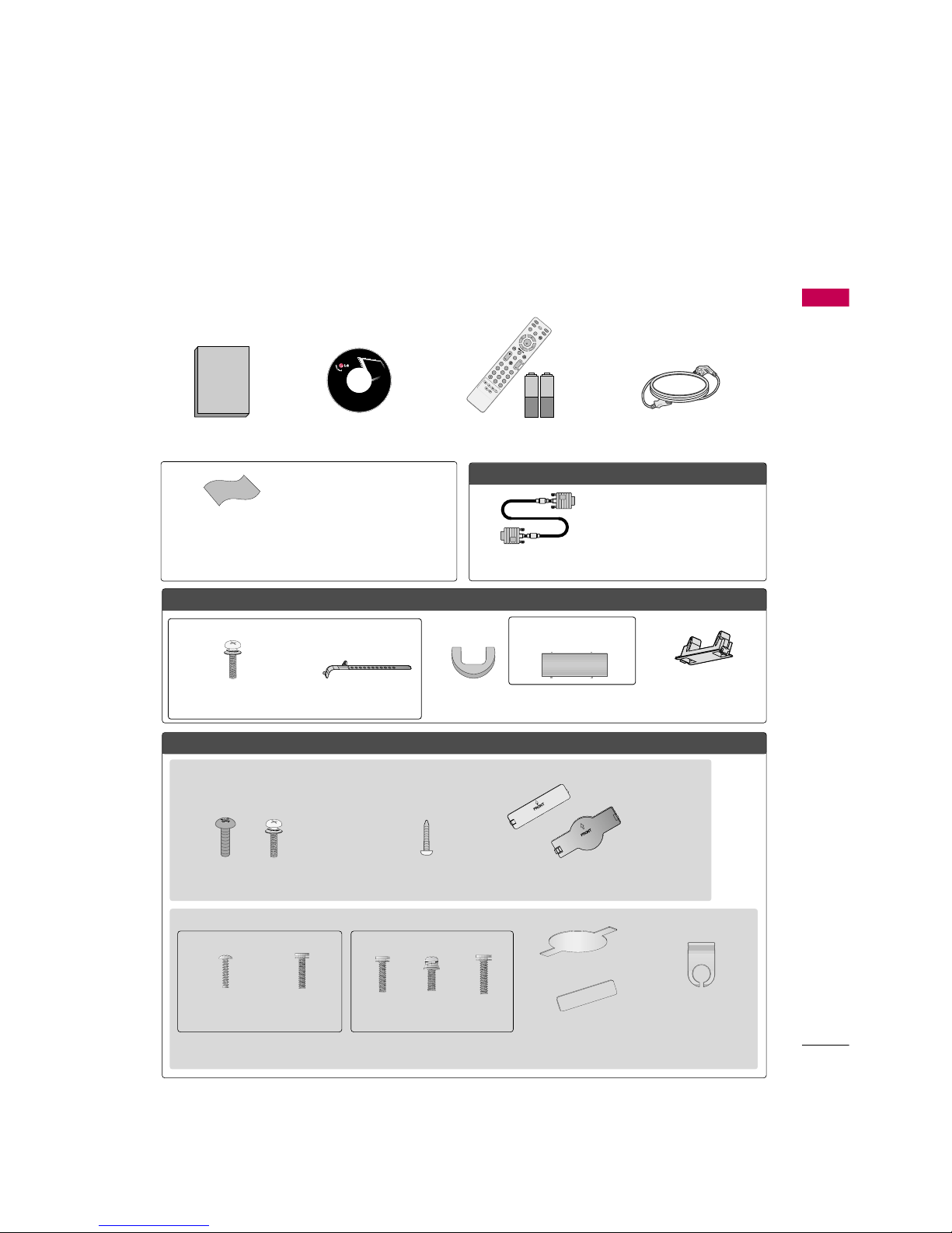
Accessories . . . . . . . . . . . . . . . . . . . . . . . . . . . . . . . . . . . . . . . . . . . . . . . . . . . . . . 7
Front Panel Information . . . . . . . . . . . . . . . . . . . . . . . . . . . . . . . . . . . . . 8
Back Panel Information . . . . . . . . . . . . . . . . . . . . . . . . . . . . . . . . . . . . 10
Stand Installation . . . . . . . . . . . . . . . . . . . . . . . . . . . . . . . . . . . . . . . . . . . . 14
Cable Management . . . . . . . . . . . . . . . . . . . . . . . . . . . . . . . . . . . . . . . . . 16
Desktop Pedestal Installation . . . . . . . . . . . . . . . . . . . . . . . . . . . . 18
Swivel Stand . . . . . . . . . . . . . . . . . . . . . . . . . . . . . . . . . . . . . . . . . . . . . . . . . . . . 18
Attaching the TV to a Desk . . . . . . . . . . . . . . . . . . . . . . . . . . . . . . 18
VESA Wall Mounting . . . . . . . . . . . . . . . . . . . . . . . . . . . . . . . . . . . . . . . . 19
Protection Cover . . . . . . . . . . . . . . . . . . . . . . . . . . . . . . . . . . . . . . . . . . . . . 20
Securing the TV to the wall to prevent falling . . . . 21
Antenna or Cable Connection . . . . . . . . . . . . . . . . . . . . . . . . . . 22
EXTERNAL EQUIPMENT SETUP
HD Receiver Setup . . . . . . . . . . . . . . . . . . . . . . . . . . . . . . . . . . . . . . . . . 23
DVD Setup . . . . . . . . . . . . . . . . . . . . . . . . . . . . . . . . . . . . . . . . . . . . . . . . . . . . . 29
VCR Setup . . . . . . . . . . . . . . . . . . . . . . . . . . . . . . . . . . . . . . . . . . . . . . . . . . . . . 33
Other A/V Source Setup . . . . . . . . . . . . . . . . . . . . . . . . . . . . . . . . . 36
PC Setup . . . . . . . . . . . . . . . . . . . . . . . . . . . . . . . . . . . . . . . . . . . . . . . . . . . . . . . . 37
USB Connection . . . . . . . . . . . . . . . . . . . . . . . . . . . . . . . . . . . . . . . . . . . . 46
Audio Out Connection . . . . . . . . . . . . . . . . . . . . . . . . . . . . . . . . . . . 47
WATCHING TV / CHANNEL CONTROL
Remote Control Functions . . . . . . . . . . . . . . . . . . . . . . . . . . . . . . . 48
Turning On the TV . . . . . . . . . . . . . . . . . . . . . . . . . . . . . . . . . . . . . . . . . . 50
Channel Selection . . . . . . . . . . . . . . . . . . . . . . . . . . . . . . . . . . . . . . . . . . . 50
Volume Adjustment . . . . . . . . . . . . . . . . . . . . . . . . . . . . . . . . . . . . . . . . . 50
Quick Menu . . . . . . . . . . . . . . . . . . . . . . . . . . . . . . . . . . . . . . . . . . . . . . . . . . . . 51
Initial Setting . . . . . . . . . . . . . . . . . . . . . . . . . . . . . . . . . . . . . . . . . . . . . . . . . . 52
On-Screen Menus Selection . . . . . . . . . . . . . . . . . . . . . . . . . . . . 54
Channel Setup
- Auto Scan (Auto Tuning) . . . . . . . . . . . . . . . . . . . . . . . . . . . 56
- Add / Delete Channel (Manual Tuning) . . . . . . 57
- Channel Editing . . . . . . . . . . . . . . . . . . . . . . . . . . . . . . . . . . . . . . . . 58
Input List . . . . . . . . . . . . . . . . . . . . . . . . . . . . . . . . . . . . . . . . . . . . . . . . . . . . . . . . 59
Input Label . . . . . . . . . . . . . . . . . . . . . . . . . . . . . . . . . . . . . . . . . . . . . . . . . . . . . 60
AV Mode . . . . . . . . . . . . . . . . . . . . . . . . . . . . . . . . . . . . . . . . . . . . . . . . . . . . . . . . 61
SIMPLINK . . . . . . . . . . . . . . . . . . . . . . . . . . . . . . . . . . . . . . . . . . . . . . . . . . . . . . . 62
USB
Entry Modes . . . . . . . . . . . . . . . . . . . . . . . . . . . . . . . . . . . . . . . . . . . . . . . . . . . 64
Photo List . . . . . . . . . . . . . . . . . . . . . . . . . . . . . . . . . . . . . . . . . . . . . . . . . . . . . . . 65
Music List . . . . . . . . . . . . . . . . . . . . . . . . . . . . . . . . . . . . . . . . . . . . . . . . . . . . . . . 69
PICTURE CONTROL
Picture Size (Aspect Ratio) Control . . . . . . . . . . . . . . . . . . 72
Preset Picture Settings
- Picture Mode - Preset . . . . . . . . . . . . . . . . . . . . . . . . . . . . . . . 74
- Color Tone - Preset . . . . . . . . . . . . . . . . . . . . . . . . . . . . . . . . . . . 75
Manual Picture Adjustment
- Picture Mode - User Mode . . . . . . . . . . . . . . . . . . . . . . . . 76
- Picture Mode - Expert Control . . . . . . . . . . . . . . . . . . 77
Picture Improvement Technology . . . . . . . . . . . . . . . . . . . . . 78
Advanced Control - Black (Darkness) Level . . . . . . . 79
Advanced Control - Eye Care . . . . . . . . . . . . . . . . . . . . . . . . . . . 80
Advanced Control - Real Cinema/Film Mode . . . . . 81
Advanced Control - TruMotion . . . . . . . . . . . . . . . . . . . . . . . . 82
TruMotion Demo . . . . . . . . . . . . . . . . . . . . . . . . . . . . . . . . . . . . . . . . . . . . . 83
Picture Reset . . . . . . . . . . . . . . . . . . . . . . . . . . . . . . . . . . . . . . . . . . . . . . . . . 84
Power Indicator . . . . . . . . . . . . . . . . . . . . . . . . . . . . . . . . . . . . . . . . . . . . . . 85
Image Sticking Minimization (ISM) Method . . . . . . 86
Power Saving Picture Mode . . . . . . . . . . . . . . . . . . . . . . . . . . . . . . 87

5
SOUND & LANGUAGE CONTROL
Auto Volume Leveler (Auto Volume) . . . . . . . . . . . . . . . . . 88
Preset Sound Settings (Sound Mode) . . . . . . . . . . . . . . 89
Sound Setting Adjustment - User Mode . . . . . . . . . . . 90
Clear Voice . . . . . . . . . . . . . . . . . . . . . . . . . . . . . . . . . . . . . . . . . . . . . . . . . . . . . 91
Balance . . . . . . . . . . . . . . . . . . . . . . . . . . . . . . . . . . . . . . . . . . . . . . . . . . . . . . . . . . 92
TV Speakers On/Off Setup . . . . . . . . . . . . . . . . . . . . . . . . . . . . . . 93
Audio Reset . . . . . . . . . . . . . . . . . . . . . . . . . . . . . . . . . . . . . . . . . . . . . . . . . . . 94
Stereo/SAP Broadcast Setup . . . . . . . . . . . . . . . . . . . . . . . . . . . 95
Audio Language . . . . . . . . . . . . . . . . . . . . . . . . . . . . . . . . . . . . . . . . . . . . . . 96
On-Screen Menus Language Selection . . . . . . . . . . . . . . 97
Caption Mode
- Analog Broadcasting System Captions . . . . . . . 98
- Digital Broadcasting System Captions . . . . . . . . 99
- Caption Option . . . . . . . . . . . . . . . . . . . . . . . . . . . . . . . . . . . . . 10 0
TIME SETTING
Clock Setting
- Auto Clock Setup . . . . . . . . . . . . . . . . . . . . . . . . . . . . . . . . . . . 101
- Manual Clock Setup . . . . . . . . . . . . . . . . . . . . . . . . . . . . . . . 102
Auto On/Off Time Setting . . . . . . . . . . . . . . . . . . . . . . . . . . . . 103
Sleep Timer Setting . . . . . . . . . . . . . . . . . . . . . . . . . . . . . . . . . . . . . . . 10 4
Auto Shut-off Setting . . . . . . . . . . . . . . . . . . . . . . . . . . . . . . . . . . . . . 10 5
PARENTAL CONTROL / RATINGS
Set Password & Lock System . . . . . . . . . . . . . . . . . . . . . . . . . . 106
Channel Blocking . . . . . . . . . . . . . . . . . . . . . . . . . . . . . . . . . . . . . . . . . . 109
Movie & TV Rating . . . . . . . . . . . . . . . . . . . . . . . . . . . . . . . . . . . . . . . . 110
Downloadable Rating . . . . . . . . . . . . . . . . . . . . . . . . . . . . . . . . . . . . . 115
External Input Blocking . . . . . . . . . . . . . . . . . . . . . . . . . . . . . . . . . . . 116
Key lock . . . . . . . . . . . . . . . . . . . . . . . . . . . . . . . . . . . . . . . . . . . . . . . . . . . . . . . . . 117
APPENDIX
Troubleshooting . . . . . . . . . . . . . . . . . . . . . . . . . . . . . . . . . . . . . . . . . . . . . 118
Maintenance . . . . . . . . . . . . . . . . . . . . . . . . . . . . . . . . . . . . . . . . . . . . . . . . . 120
Product Specifications . . . . . . . . . . . . . . . . . . . . . . . . . . . . . . . . . . . 121
Programming the Remote Control . . . . . . . . . . . . . . . . . . 124
IR Codes . . . . . . . . . . . . . . . . . . . . . . . . . . . . . . . . . . . . . . . . . . . . . . . . . . . . .127
External Control Through RS-232C . . . . . . . . . . . . . . . . .12 9
Open Source License . . . . . . . . . . . . . . . . . . . . . . . . . . . . . . . . . . . . . .136

6
FEATURE OF THIS TV
is a trademark of SRS Labs, Inc.
TruSurround XT technology is incorporated under
license from SRS Labs, Inc.
Manufactured under license from Dolby Laboratories.
“
Dolby
“and the double-D symbol are trademarks of
Dolby Laboratories.
FOR LCD TV
■
If the TV feels cold to the touch, there may be a small “flicker” when it is turned on. This is normal, there is
nothing wrong with TV.
■
Some minute dot defects may be visible on the screen, appearing as tiny red, green, or blue spots. However, they
have no adverse effect on the monitor's performance.
■
Avoid touching the LCD screen or holding your finger(s) against it for long periods of time. Doing so may produce
some temporary distortion effects on the screen.
On Disposal (Only Hg lamp used LCD TV)
The fluorescent lamp used in this product contains a small amount of mercury. Do not dispose of this product with
general household waste. Disposal of this product must be carried out in accordance to the regulations of your local
authority.

PREPARATION
7
PREPARATION
ACCESSORIES
Ensure that the following accessories are included with your TV. If an accessory is missing, please contact the
dealer where you purchased the TV.
The accessories included may differ from the images below.
Option Extras
For LCD TV models
For Plasma TV models
* Wipe spots on the exterior only with
the polishing cloth.
* Do not wipe roughly when removing
stain. Excessive pressure may cause
scratch or discoloration.
Polishing Cloth
(This feature is not available
for all models.)
Copyright©2007 LGE,
AllRights Reserved.
D-sub 15 pin Cable
1.5V 1.5V
Owner’s Manual Power Cord
Remote Control,
Batteries
INPUT
FAV
MUTE
TV
STB
POWER
Q.MENUMENU
AVMODE
RETURN
ENTER
VOLCH
123
456
78
0
9
FLASHBK
P
A
G
E
DVD
VCR
CD Manual
When using the VGA (D-sub 15 pin
cable) PC connection, the user
must use shielded signal interface
cables with ferrite cores to maintain
standards compliance.
32/37/42LG30, 37/42/47/52LG50, 32/42/47/52LG70, 47LG90
Bolts for stand assembly
(Refer to P.14)
(Only 32/37/42LG30, 37/42LG50,
32/42LG70)
Protection Cover
(Refer to P.20)
Screw for stand fixing
(Refer to P.18)
(Only 32LG30/70,
42LG30/50)
x 4 x 4
32/37/42/47/52LG60, 42LGX
Protection Cover
(Refer to P.20)
Cable Management
Clip
2EA
(M4x16)
4EA
(M4x20)
1EA4EA32LG60: 3EA
37LG60: 4EA
Bolts for stand assembly
(Refer to P.15)
(Only 32/37LG60) (Only 42LG60, 42LGX)
Cable Management Clip
Protection Cover
(Refer to P.20)
(Only 50PG25,
50/60PG60, 50/60PG70)
(Only 42PG25)
or
or
Cable Holder
Bolts for stand assembly
(Refer to P.14)
x 4

PREPARATION
8
FRONT PANEL INFORMATION
PREPARATION
■
Image shown may differ from your TV.
■
NOTE: If your TV has a protection tape attached, remove the tape.
And then wipe the TV with a cloth (If a polishing cloth is included with your TV, use it).
Plasma TV Models
CH
VOL
MENU
INPUT ENTER
INPUT
Button
MENU
Button
ENTER
Button
VOLUME
(-, +) Buttons
CHANNEL
(EE,D)Buttons
Remote Control Sensor
POWER Button
Power/Standby Indicator
Illuminates red in standby mode.
Illuminates blue when the TV is switched on.
LCD TV Models
POWER Button
Power/Standby Indicator
Illuminates red in standby mode.
Illuminates blue when the set is switched on.
(Can be adjusted using Power Indicator in
the OPTION menu. Gp.85)
CH
VOL
MENU
INPUT
ENTER
CHANNEL ( , )
Buttons
VOLUME (+, -)
Buttons
ENTER Button
MENU Button
INPUT Button
Intelligent Sensor
Adjusts picture according to the surrounding
conditions
32/42/47/52LG70, 47LG90
Remote Control Sensor

PREPARATION
9
LCD TV Models
POWER Button
Power/Standby Indicator
Illuminates red in standby mode.
Illuminates blue when the set is switched on.
(Can be adjusted using Power Indicator in
the OPTION menu. Gp.85)
CH
VOL
MENU
INPUT
ENTER
CHANNEL ( , )
Buttons
VOLUME (+, -)
Buttons
ENTER Button
MENU Button
INPUT Button
Intelligent Sensor
Adjusts picture according to the
surrounding conditions.
Intelligent Sensor (Except 32/37/42LG30)
Adjusts picture according to the surrounding
conditions
ENTER
CH
VOL
MENU
INPUT
CHANNEL ( , )
Buttons
VOLUME (+, -)
Buttons
ENTER Button
MENU Button
INPUT Button
32/37/42LG30, 37/42/47/52LG50
32/37/42/47/52LG60, 42LGX
POWER Button
Remote Control Sensor
Power/Standby Indicator
Illuminates red in standby mode.
Illuminates white when the set is switched on.
(Can be adjusted using Power Indicator in
the OPTION menu. Gp.85)
Remote Control Sensor

PREPARATION
10
BACK PANEL INFORMATION
PREPARATION
Plasma TV Models
■
Image shown may differ from your TV.
12
AV IN 2
L/MONO
R
AUDIO
VIDEO
USB IN
HDMI IN 4
9
10
1
RGB IN
COMPONENT IN
AUDIO
(RGB/DVI)
RGB(PC)
ANTENNA/
CABLE IN
1
2
RS-232C IN
(CONTROL & SERVICE)
VIDEO
AUDIO
VIDEO
AUDIO OUT
OPTICAL COAXIAL
MONO
( )
AUDIO
S-VIDEO
DIGITAL AUDIO OUT
AV IN 1
HDMI/DVI IN
3
2
1
REMOTE
CONTROL IN
1
3
4
6
7
8
2
9
5

PREPARATION
11
LCD TV Models
AV IN 2
L/MONO
R
AUDIO
VIDEO
HDMI IN 3 USB IN
RGB IN
COMPONENT IN
AUDIO
(RGB/DVI)
RGB(PC)
REMOTE
CONTROL IN
ANTENNA/
CABLE IN
1
2
RS-232C IN
(CONTROL & SERVICE)
VIDEO
AUDIO
OPTICAL COAXIAL
DIGITAL AUDIO OUT
AUDIO OUT
AV IN 1
HDMI/DVI IN
2
1
VIDEO
MONO
( )
AUDIO
S-VIDEO
1
3
4
6
7
8
2
9
9
5
RGB IN
COMPONENT IN
AUDIO
(RGB/DVI)
RGB(PC)
REMOTE
CONTROL IN
ANTENNA/
CABLE IN
1
2
RS-232C IN
(CONTROL & SERVICE)
VIDEO
AUDIO
DIGITAL
AUDIO OUT
OPTICAL
AUDIO OUT
AV IN 1
VIDEO
MONO
( )
AUDIO
S-VIDEO
2
1
HDMI/DVI IN
1
3
4
6
7
8
2
9
5
10
1
AV IN 2
L/MONO
R
AUDIO
VIDEO
USB
SERVUCE ONLY
HDMI IN 3
9
11
1
37/42/47/52LG50
32/37/42LG30
12

PREPARATION
12
PREPARATION
AV IN 2
L/MONO
R
AUDIO
VIDEO
HDMI IN 4 USB IN
9
10
1
■
Image shown may differ from your TV.
32/37/42/47/52LG60, 42LGX
32/42/47/52LG70, 47LG90
LCD TV Models
12
12
RGB IN
COMPONENT IN
AUDIO
(RGB/DVI)
RGB(PC)
REMOTE
CONTROL IN
ANTENNA/
CABLE IN
RS-232C IN
(CONTROL & SERVICE)
VIDEO
AUDIO
OPTICAL COAXIAL
DIGITAL AUDIO OUT
AUDIO OUT
AV IN 1
HDMI/DVI IN
2
3
1
VIDEO
MONO
( )
AUDIO
S-VIDEO
2
1
13
4
6
7
8
2
9
5
AV IN
L/MONO
R
AUDIO
VIDEO
HDMI IN 4 USB IN
9
10
1
(RGB/DVI)
AUDIO
RGB(PC)
REMOTE
CONTROL IN
RS-232C IN
(SERVICE ONLY)
OPTICAL
COAXIAL
DIGITAL
AUDIO OUT
123
COMPONENT IN
2
1
VIDEO
AUDIO
HDMI/DVI INRGB IN
ANTENNA/
CABLE IN
2
7
4
1
3
6
11

PREPARATION
13
HDMI/DVI IN, HDMI IN
Digital Connection.
Supports HD video and Digital audio. Doesn’t
support 480i.
Accepts DVI video using an adapter or HDMI to
DVI cable (not included).
COMPONENT IN
Analog Connection.
Supports HD.
Uses a red, green, and blue cable for video & red
and white for audio.
RGB (PC)
Analog PC Connection. Uses a D-sub 15 pin cable
(VGA cable).
AUDIO (RGB/DVI)
1/8” headphone jack for analog PC audio input.
REMOTE CONTROL IN PORT
For a wired remote control.
RS-232C IN (CONTROL & SERVICE) PORT
Used by third party devices.
ANTENNA/CABLE IN
Connect over-the air signals to this jack.
Connect cable signals to this jack.
DIGITAL AUDIO OUT
Digital audio output for use with amps and home
theater systems.
Includes an optical and/or coaxial connection.
Note: In standby mode, these ports do not work.
AUDIO OUT
Analog audio output for use with amps and home
theater systems.
AV (Audio/Video) IN
Analog composite connection. Supports standard
definition video only (480i).
S-VIDEO
Better quality than standard composition.
Supports standard definition video only (480i).
USB INPUT
Used for viewing photos and listening to MP3s.
USB SERVICE ONLY or RS-232C IN (SERVICE
ONLY)
Used for software updates.
Power Cord Socket
For operation with AC power.
Caution: Never attempt to operate the TV on DC
power.
1
2
3
4
5
6
7
9
10
11
12
8

PREPARATION
14
PREPARATION
STAND INSTALLATION
■
Image shown may differ from your TV.
■
When assembling the desk type stand, check whether the bolt is fully tightened. (If not tightened fully, the prod-
uct can tilt forward after the product installation). If you tighten the bolt with excessive force, the bolt can devi-
ate from abrasion of the tightening part of the bolt.
■
You can remove the stand before installing the TV on a wall mount by performing the stand instructions in
reverse.
Carefully place the TV screen side down on a
cushioned surface to protect the screen from
damage.
Assemble the TV as shown.
Fix the 4 bolts securely using the holes in the
back of the TV.
1
2Assemble the parts of the STAND BODY
with COVER BASE of the TV.
2
3Assemble the TV as shown.
3
Fix the 4 bolts securely using the holes in the
back of the TV.
4
Only 42PG25 Only 32/37/42LG30, 37/42LG50, 32/42LG70,
STAND BODY
COVER BASE
Carefully place the TV screen side down on a
cushioned surface to protect the screen from
damage.
1

PREPARATION
15
Assemble the parts of the STAND BODY
with COVER BASE of the TV.
2
Assemble the TV as shown.
3
Fix the 4 bolts securely using the holes in the
back of the TV.
4
Only 32/37/42LG60, 42LGX
Carefully place the TV screen side down on a
cushioned surface to protect the screen from
damage.
1
32LG60 37LG60 42LG60, 42LGX
(M4x16)
STAND BODY STAND BODY
COVER BASE
STAND BODY
COVER BASE
COVER BASE
(M4x20)

PREPARATION
16
STAND DETACHMENT
PREPARATION
■
Image shown may differ from your TV.
■
Image shown may differ from your TV.
LCD TV Models
You can remove the stand before installing the TV on
a wall mount by performing the previous stand instruc-
tions in reverse. After removing the stand, install the
included protection cover over the hole for the
stand.
Press the PROTECTION COVER into the TV until
you hear it click.
After removing the protection paper from the
protection cover, adhere it to the TV as shown.
PROTECTION COVER
47/52LG50/70 47/52LG60
Carefully place the TV screen side down on a
cushioned surface to protect the screen from
damage.
1
Loose the bolts from TV.
2
Detach the stand from TV.
2
Plasma TV Models
50PG25/60 60PG60

PREPARATION
17
VESA WALL MOUNTING
Install your wall mount on a solid wall perpendicular to the floor. When attaching to other building materials, please
contact your nearest dealer.
If installed on a ceiling or slanted wall, it may fall and result in severe personal injury.
We recommend that you use an LG brand wall mount when mounting the TV to a wall.
GDo not install your wall mount kit while your TV is turned on. It may result in personal injury due to electric
shock.
CAUTION
GScrew length needed depends on the wall mount
used. For further information, refer to the instruc-
tions included with the mount.
GStandard dimensions for wall mount kits are shown
in the table.
GGWhen purchasing our wall mount kit, a detailed
installation manual and all parts necessary for
assembly are provided.
GGDo not use screws longer then the standard dimen-
sion, as they may cause damage to the inside to
the TV.
GFor wall mounts that do not comply with the VESA
standard screw specifications, the length of the
screws may differ depending on their specifica-
tions.
GDo not use screws that do not comply with the
VESA standard screw specifications.
Do not use fasten the screws too strongly, this may
damage the TV or cause the TV to a fall, leading to
personal injury. LG is not liable for these kinds of
accidents.
GLG is not liable for TV damage or personal injury
when a non-VESA or non specified wall mount is
used or the consumer fails to follow the TV installa-
tion instructions.
NOTE
!
A
B
Product Model VESA Standard Screw Quantity
32LG30, 32LG60, 32LG70
37LG30, 37LG60, 37LG50
42LG30, 42LG50, 42LG60, 42LG70, 42LGX
47LG50, 47LG60, 47LG70, 47LG90
52LG50, 52LG60, 52LG70
42PG25
50PG25, 50PG60, 50PG70
60PG60, 60PG70
200 * 10 0
200 * 200
800 * 400
400 * 400
600 * 400
M4
M6
M6
M6
M8
4
4
4
4
4
LCD TV
PLASMA TV

PREPARATION
18
CABLE MANAGEMENT
PREPARATION
■
Image shown may differ from your TV.
Plasma TV Models
Connect the cables as necessary.
To connect additional equipment, see the
EXTERNAL EQUIPMENT SETUP section.
Install the CABLE MANAGEMENT CLIP as
shown.
If your TV has the CABLE HOLDER, install it
as shown and bundle the cables.
1
2
GDo not hold the CABLE MANAGEMENT CLIP when moving the TV.
- If the TV is dropped, you may be injured or the product may be broken.
NOTE
!
How to remove the CABLE MANAGEMENT CLIP
GFirst, press the cable management. Hold the
CABLE MANAGEMENT CLIP with both
hands and pull it upward.
GSeparate CABLE MAN-
AGEMENT CLIP from TV
by pressing two latches.
GHold the CABLE MAN-
AGEMENT CLIP with both
hands and pull it upward.
42PG25 50PG25, 50/60PG60, 50/60PG70
CABLE MANAGEMENT CLIP
CABLE HOLDER

PREPARATION
19
LCD TV Models
Connect the cables as necessary.
To connect additional equipment, see the
EXTERNAL EQUIPMENT SETUP section.
Install the CABLE MANAGEMENT CLIP as
shown.
CABLE MANAGEMENT CLIP
1
2
Align the hole with the tab on the CABLE
MANAGEMENT CLIP.
Turn the CABLE MANAGEMENT CLIP as
shown.
Note: This cable management clip can be bro-
ken by excessive pressure.
Connect the cables as necessary.
To connect additional equipment, see the
EXTERNAL EQUIPMENT SETUP section.
1
2
Put the cables inside the CABLE MANAGEMENT
CLIP and snap it closed.
3
32/37/42/47/52LG60, 42LGX32/37/42LG30, 37/42/47/52LG50,
32/42/47/52LG70, 47LG90
Other manuals for 32LG30 Series
9
This manual suits for next models
23
Table of contents
Other LG LCD TV manuals