LG 42PC5D Series User manual

DVB is a registered trademark
of the DVB Project
42PC5D*
50PC5D*
PLASMA TV M DELS
IIDD NNuummbbeerr ::4721: 42PC5D
4720: 50PC5D
Please read this manual carefully before operatin
your set. Retain it for future reference.
Record model number and serial number of the set.
Refer to the label on the back cover and quote this
information.
To your dealer when requirin service.


1
ACCESSORIES
AACCCCEESSSSOORRIIEESS
Ensure that the following accessories are included with your product. If an accessory is missing, please contact
the dealer where you purchased the product.
wner’s Manual Remote Control
OK
TVD/A
INPUT
DVD
EXIT
VOL
SIZE
INDEX
TIME
REVEAL
Q.VIEW
LIST
MENU
TEXT
GUIDE
VCR
POWER
123
456
789
0
?
RATIO
FAV
SUBTITLE
SLEEP
I/II
BRIGHT
SIMPLINK
MUTE
INFO
PAGE
PR
INPUT
MODE
i
i
Batteries
■
Lightly wipe any stains or fingerprints on the surface of the
TV with the polishing cloth.
■
Do not use excessive force. This may cause scratching or
discolouration.
Polishing Cloth
Power Cord
Polishing cloth for use on the
screen

CONTENTS
2
CONTENTS
ACCESS RIES
. . . . . . . . . . . . . . . . . . . . . . . . . . . . . . . . . . . . . . . . . . .
1
PREPARATI N
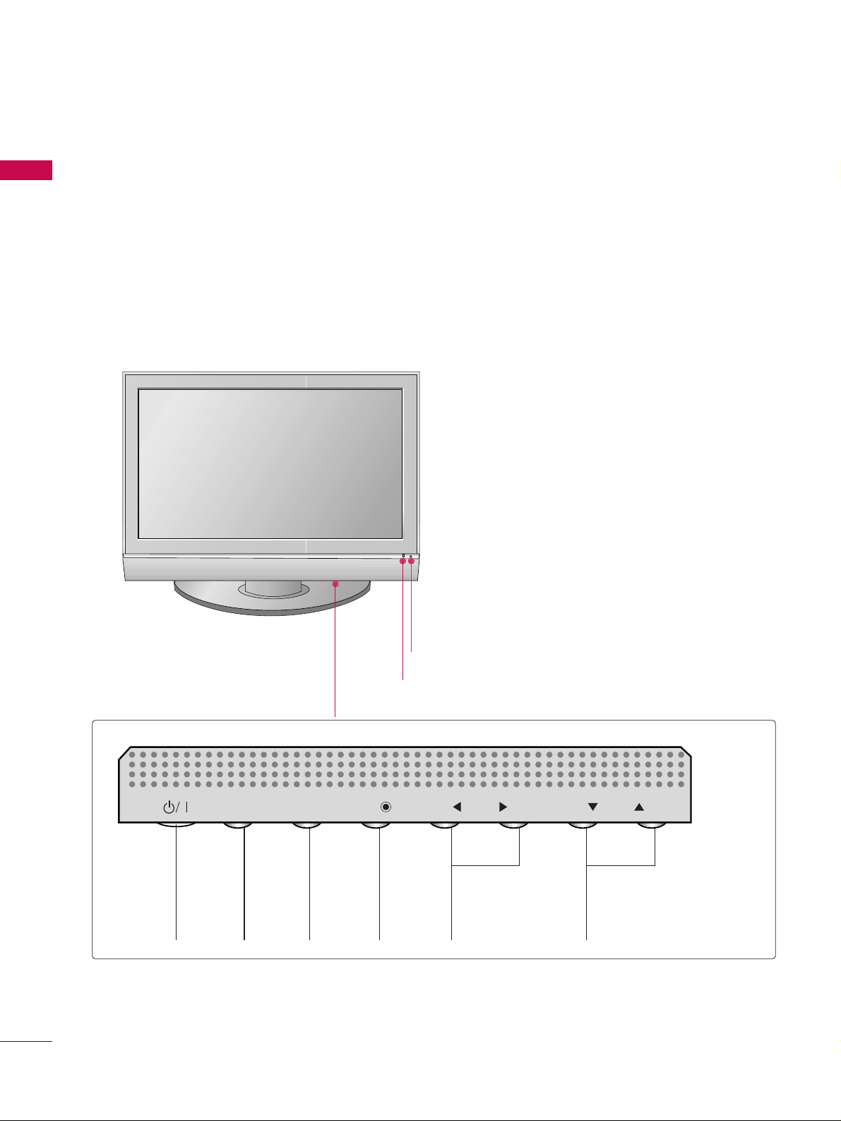
Front Panel Controls . . . . . . . . . . . . . . . . . . . . . . 4
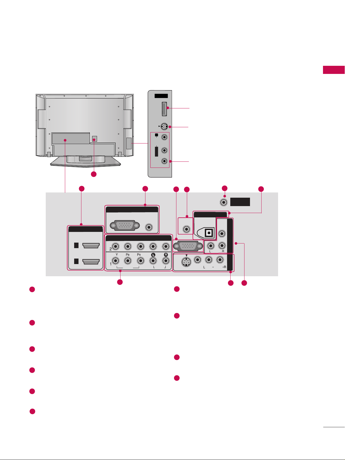
Back Panel Information . . . . . . . . . . . . . . . . . . . . .5
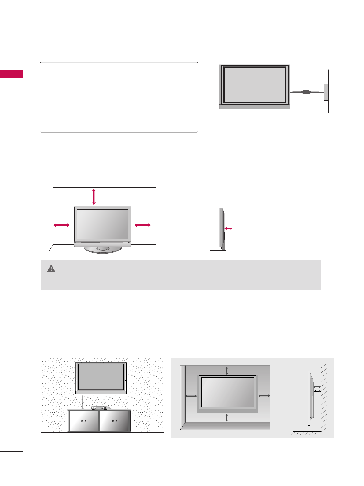
Attachin the TV to a Wall . . . . . . . . . . . . . . . . . . 6
Back Cover for Wire Arran ement . . . . . . . . . . . . 7
Desktop Pedestal Installation . . . . . . . . . . . . . . . . 8
Wall Mount: Horizontal Installation . . . . . . . . . . . 8
Antenna Connection . . . . . . . . . . . . . . . . . . . . . . . 9
EXTERNAL EQUIPMENT SETUP
HD Receiver Setup . . . . . . . . . . . . . . . . . . . . . . . . . . . . . . . . . . . . . . . . . 10
DVD Setup . . . . . . . . . . . . . . . . . . . . . . . . . . . . . . . . . . . . . . . . . . . . . . . . . . . . . . 13
VCR Setup . . . . . . . . . . . . . . . . . . . . . . . . . . . . . . . . . . . . . . . . . . . . . . . . . . . . . . 15
Other A/V Source Setup . . . . . . . . . . . . . . . . . . . . . . . . . . . . . . . . . . 17
PC Setup . . . . . . . . . . . . . . . . . . . . . . . . . . . . . . . . . . . . . . . . . . . . . . . . . . . . . . . . 18
- Screen Setup for PC Mode . . . . . . . . . . . . . . . . . . . . . . . . . 21
AV Output Setup . . . . . . . . . . . . . . . . . . . . . . . . . . . . . . . . . . . . . . . . . . . . 23
Di ital Audio Output Setup . . . . . . . . . . . . . . . . . . . . . . . . . . . . . 23
WATCHING TV / PR GRAMME C NTR L
Remote Control Key Functions . . . . . . . . . . . . . .24
Turnin on the TV . . . . . . . . . . . . . . . . . . . . . . . . 26
Initializin Setup . . . . . . . . . . . . . . . . . . . . . . . . . 26
Pro ramme Selection . . . . . . . . . . . . . . . . . . . . . 27
Volume Adjustment . . . . . . . . . . . . . . . . . . . . . . 27
On-Screen Menus Selection and Adjustment . . 28
Factory Reset . . . . . . . . . . . . . . . . . . . . . . . . . . . 29
Model Info . . . . . . . . . . . . . . . . . . . . . . . . . . . . . . 29
Auto Pro ramme Tunin . . . . . . . . . . . . . . . . . . .30
Manual Pro ramme Tunin . . . . . . . . . . . . . . . . . 32
Fine Tunin . . . . . . . . . . . . . . . . . . . . . . . . . . . . . 34
Assi nin a Station Name . . . . . . . . . . . . . . . . . 35
Pro ramme Edit . . . . . . . . . . . . . . . . . . . . . . . . . .36
Input List . . . . . . . . . . . . . . . . . . . . . . . . . . . . . . . 38
Callin Up the Channel List . . . . . . . . . . . . . . . . 39
Input Source Selection . . . . . . . . . . . . . . . . . . . . 40
SIMPLINK . . . . . . . . . . . . . . . . . . . . . . . . . . . . . . . 41
Key Lock . . . . . . . . . . . . . . . . . . . . . . . . . . . . . . . 43
EPG (ELECTR NIC PR GRAMME GUIDE)
Switch on/off EPG . . . . . . . . . . . . . . . . . . . . . . . 44
Select a pro ramme . . . . . . . . . . . . . . . . . . . . . . 44
Button Function in NOW/NEXT Guide Mode . 45
Button Function in 7 Days Guide Mode . . . . . . 45
Button Function in Extended Description Box . 46
Button Function in Reservation Settin Mode . . 46
PICTURE C NTR L
Picture Size (Aspect Ratio) Control . . . . . . . . . .47
Preset Picture Settin s
- Picture Mode - Preset . . . . . . . . . . . . . . . . 48
- Auto Colour Tone Control
(Warm/Medium/Cool) . . . . . . . . . . . . . . . .49
Manual Picture Adjustment
- Picture Mode - User Option . . . . . . . . . . . 50
- Colour Tone - User Option. . . . . . . . . . . . .51
Bri htness Adjustment . . . . . . . . . . . . . . . . . . . . . . 52
XD - Picture Improvement Technolo y . . . . . . . . . . . 53
Advanced - Cinema . . . . . . . . . . . . . . . . . . . . . . . 54
Advanced - Black(Darkness) Level . . . . . . . . . . . 55
Picture Reset . . . . . . . . . . . . . . . . . . . . . . . . . . . . 56
Ima e Stickin Minimization(ISM) Method . . . . 57
Low Power . . . . . . . . . . . . . . . . . . . . . . . . . . . . . . 58

CONTENTS
3
After readin this manual, keep it handy for future reference.
S UND & LANGUAGE C NTR L
Auto Volume Leveler (Auto Volume) . . . . . . . . . 59
Preset Sound Settin s - Sound Mode . . . . . . . . 60
Sound Settin Adjustment - User Mode . . . . . . . . 61
Balance . . . . . . . . . . . . . . . . . . . . . . . . . . . . . . . . .63
TV Speakers On/ Off Setup . . . . . . . . . . . . . . . . 64
I/II
- Stereo/Dual Reception . . . . . . . . . . . . . . . . . 65
- Speaker Sound Output Selection . . . . . . . . 65
Subtitle . . . . . . . . . . . . . . . . . . . . . . . . . . . . . . . . 66
TIME SETTING
Clock Settin . . . . . . . . . . . . . . . . . . . . . . . . . . . . 67
Auto On/ Off Timer Settin . . . . . . . . . . . . . . . .69
Sleep Timer Settin . . . . . . . . . . . . . . . . . . . . . . .70
Auto Shut-off Settin . . . . . . . . . . . . . . . . . . . . . 71
PARENTAL C NTR L / RATINGS
Set Password & Lock System . . . . . . . . . . . . . . . 72
Pro ramme Blockin . . . . . . . . . . . . . . . . . . . . . . 75
Parental Guidance . . . . . . . . . . . . . . . . . . . . . . . . 76
External Input Blockin . . . . . . . . . . . . . . . . . . . . 77
TELETEXT
Switch On/Off . . . . . . . . . . . . . . . . . . . . . . . . . . 78
Simple Text . . . . . . . . . . . . . . . . . . . . . . . . . . . . . 78
TOP Text . . . . . . . . . . . . . . . . . . . . . . . . . . . . . . . 78
Fastext . . . . . . . . . . . . . . . . . . . . . . . . . . . . . . . . . 79
Special Teletext Functions . . . . . . . . . . . . . . . . . 79
APPENDIX
Troubleshootin . . . . . . . . . . . . . . . . . . . . . . . . . .80
Maintenance . . . . . . . . . . . . . . . . . . . . . . . . . . . .82
Product Specifications . . . . . . . . . . . . . . . . . . . . 83
Pro rammin the Remote Control . . . . . . . . . . 84
IR Codes . . . . . . . . . . . . . . . . . . . . . . . . . . . . . . . 87
External Control throu h RS-232C . . . . . . . . . . 89
Open Source License . . . . . . . . . . . . . . . . . . . . . 95

RE ARATION
4
FRONT ANEL CONTROLS
RE ARATION
■
This is a simplified representation of the front panel. Ima e shown may differ from your TV.
■
If your product has a protection film attached, remove the film and then wipe the product with a polishin
cloth.
PR
VOL
OK
MENU
INPUT
Remote Control Sensor
ower/Standby Indicator
• illuminates red in standby mode.
• illuminates reen when the set is switched on.
ROGRAMME
VOLUME
MENU OK IN UT
OWER
PR
VOL
OK
MENU
INPUT

RE ARATION
5
BACK ANEL INFORMATION
■
This is a simplified representation of the back panel . Ima e shown may differ from your TV.
AV 1 AV 2
ANTENNA
IN
VARIABLE AUDIO OUT
VIDEO
AUDIO
COMPONENT IN
AV IN 3
L/MONO
R
AUDIO
VIDEO
HDMI/DVI IN HDMI IN
12
RGB IN
S-VIDEO
HDMI/DVI INHDMI/DVI IN
2
COMPONENT INCOMPONENT IN
VIDEOVIDEO
AUDIOAUDIO
RGB INRGB IN
RGB (PC)RGB (PC) AUDIOAUDIO
(RGB/DVI)(RGB/DVI)
AV IN 1AV IN 1
VIDEOVIDEO
S-VIDEO
S-VIDEO
AUDIOAUDIO
MONO
()
RS-232C INRS-232C IN
(CONTROL & SERVICE)(CONTROL & SERVICE)
AV OUT
AV OUT
REMOTEREMOTE
CONTROL INCONTROL IN
DIGITAL AUDIODIGITAL AUDIO
OUTOUT
OPTICALPTICAL VIDEOVIDEO
AUDIO
ANTENNA
IN
HDMI/DVI IN
COMPONENT IN
VIDEO
AUDIO
RGB IN
RGB (PC) AUDIO
(RGB/DVI)
AV IN 1
VIDEO
S-VIDEO AUDIO
( )
RS-232C IN
(CONTROL & SERVICE)
AV OUT
REMOTE
CONTROL IN
DIGITAL
AUDIO
OUT
OPTICAL VIDEO
ANTENNAANTENNA
ININ
1
HDMI/DVI IN
Connect a HDMI si nal.
Or DVI(VIDEO)si nal to the this port with a
HDMI to DVI cable.
RGB/AUDIO IN
Connect the output from a set top box or PC to
the appropriate input port.
RS-232C IN (CONTROL &SERVICE) ORT
Connect to the RS-232C port on a PC.
Remote Control ort
Connect your wired remote control.
ANTENNA IN
Connect RF antenna (UHF) to this jack.
DIGITAL AUDIO OUT
Connect di ital audio from various types of
equipment. Note: In standby mode, these ports
do not work.
COM ONENT IN
Connect a component video/audio device to
these jacks.
AV (Audio/Video) IN 1
Connect audio/video output from an external
device to these jacks.
S-VIDEO
Connect S-Video out from an S-VIDEO device.
AV OUT
Connect a second TV or monitor.
ower Cord Socket
For operation with AC power.
Caution: Never attempt to operate the TV on DC
power.
1
6
7
8
9
10
2
3
4
5
124
78
356
9
10
AV IN 2V IN 2
L/L/MONOMONO
R
AUDIOAUDIO
VIDEOVIDEO
S-VIDEO
SVC OnlySVC Only
USB port
(Service only)
S-VIDEO Input
Connect S-Video out from an
S-VIDEO device.
AUDIO/VIDEO Input
Connect audio/video output from
an external device to these jacks.

PREPARATION
6
PREPARATION
ATTACHING THE TV TO A WALL
APurchase the eye-bolts or TV brackets/bolts to fix the TV to the wall on the market.
APosition the TV close to the wall to avoid the possibility o it alling when pushed.
AThe instructions shown below are a sa er way to set up the TV, which is to ix it to the wall, avoiding the
possibility o it alling orwards i pulled. This will prevent the TV rom alling orward and causing injury.
This will also prevent the TV rom damage. Ensure that children do not climb or hang rom the TV.
NOTE
!
G When moving the TV undo the cords irst.
G Use a plat orm or cabinet string and large enough to support the size and weight o the TV.
G To use the TV sa ely make sure that the height o the bracket on the wall and on the TV is the same.
3
Use the eye-bolts or TV brackets/bolts to fix the product to the wall as shown in the picture.
(If your TV has bolts in the eyebolts loosen then bolts.)
* Insert the eye-bolts or TV brackets/bolts and tighten them securely in the upper holes.
Secure the wall brackets with bolts to the wall.
Ensure that both brackets are even.
Use a strong cord to secure the TV.
Secure the cord in such a way that it becomes taught when the TV is in position.
1
2
3
2
1

RE ARATION
7
N TE
!
GG Do not use the CABLE MANAGEMENT to lift the TV.
- If the TV is dropped, you may be injured or the TV may be damaged.
Grip the CABLE MANAGEMENT and push the cover upwards.
Connect the cables as necessary.
To connect additional equipment, see the External equipment Setup section of the manual.
1
2
Reinstall the CCAABBLLEE MMAANNAAGGEEMMEENNTTas shown.
3
BACK COVER FOR WIRE ARRANGEMENT
■
Here shown may be somewhat different from your TV.
CABLE MANAGEMENT

RE ARATION
8
RE ARATION
DESKTO EDESTAL INSTALLATION
For adequate ventilation allow a clearance of 4” (10cm) all around the TV .
GGEnsure adequate ventilation by followin the clearance recommendations.
CAUTI N
Power Supply
Circuit breaker
EARTHING
Ensure that you connect the earth wire to prevent
possible electric shock. If roundin methods are not
possible, have a qualified electrician install a separate
circuit breaker.
Do not try to earth the TV by connectin it to tele-
phone wires, li htenin rods or as pipes.
4 inches
4 inches
4 inches
4 inches
WALL MOUNT: HORIZONTAL INSTALLATION
For adequate ventilation allow a clearance of 4” (10cm) all around the TV.
Detailed installation instructions are available from your dealer.
4 inches
4 inches
4 inches
4 inches
4 inches

RE ARATION
9
ANTENNA CONNECTION
Wall Antenna Socket or Outdoor Antenna without a Cable Box Connections.
For optimum picture quality, adjust antenna direction if needed.
ANTENNA
IN
Multi-family Dwellings/Apartments
(Connect to wall antenna socket)
Single-family Dwellings /Houses
(Connect to wall jack for outdoor antenna)
utdoor
Antenna
(VHF, UHF)
Wall
Antenna
Socket
RF Coaxial Wire (75 ohm)
GGThe TV will let you know when the analo ue, cable, and di ital pro ramme scans are complete.
N TE
!
ANTENNA
IN
■In poor si nal areas, to achieve better picture quality it may be necessary to install a si nal amplifier to
the antenna.
■If the antenna needs to be split for two TV’s, install a 2-Way Si nal Splitter.
■If the antenna is not installed properly, contact your dealer for assistance.
Antenna
UHF
Signal
Amplifier
VHF
■To prevent damage do not connect to the mains outlet until all connections are made between the devices.

EXTERNAL EQUI MENT SETU
10
EXTERNAL EQUI MENT SETU
■To avoid damaging any equipment, never plug in any power cords until you have finished connecting all equipment.
HD RECEIVER SETU
Connecting with a Component cables
Connect the video outputs (Y, PB, PR)of the di ital set
top box to the CCOOMMPPOONNEENNTT IINN VVIIDDEEOO 11jacks on
the set. Match the jack colours.
(Y = reen, PB= blue, and PR= red)
Connect the audio output of the di ital set-top box to
the CCOOMMPPOONNEENNTT IINN AAUUDDIIOO 11jacks on the set.
Turn on the di ital set-top box.
(Refer to the owner’s manual for the di ital set-top box.)
Select CCoommppoonneenntt 11input source usin the IINNPPUUTT
button on the remote control.
If connected to CCOOMMPPOONNEENNTT IINN 22input, select
CCoommppoonneenntt 22input source.
2
1
3
4
RGB IN
RGB (PC)
DIGITAL
AUDIO
OUT
COMPONENT INCOMPONENT IN
VIDEOVIDEO
AUDIOAUDIO
Y L RPBPR
COMPONENT IN
VIDEO
AUDIO
DIGITAL
AUDIO
OUT
RGB IN
RGB (PC) AUDIO
(RGB/DVI)
COMPONENT IN
VIDEO
AUDIO
RGB IN
RGB (PC)
DIGITAL
AUDIO
OUT
HDMI/DVI IN
COMPONENT IN
VIDEO
AUDIO
DIGITAL
AUDIO
OUT
HDMI/DVI IN
RGB IN
AUDIO
(RGB/DVI)
12
Si nal
480i
480p
576i
576p
720p
1080 i
1080 p
Component 1/2
Yes
Yes
Yes
Yes
Yes
Yes
Yes
HDMI/DVI 1, 2, 3
No
Yes
No
Yes
Yes
Yes
Yes

EXTERNAL EQUI MENT SETU
11
Connecting with HDMI cable
Connect the di ital set-top box to HHDDMMII//DDVVII IINN 11or 22
jack on the set.
No separate audio connection is necessary.
Turn on the di ital set-top box.
(Refer to the owner’s manual for the di ital set-top box.)
Select HHDDMMII11or HHDDMMII22input source usin the IINNPPUUTT
button on the remote control.
2
1
GGIf the di ital set-top box supports Auto HDMI function, the
output resolution of the source device will be automatically
set to 1280x720p.
GGIf the di ital set-top box player does not support Auto
HDMI, you need to set the output resolution appropriately.
To et the best picture quality, adjust the output resolution
of the source device to 1280x720p.
N TE
!
3
RGB IN
RGB (PC)
DIGITAL
AUDIO
OUT
COMPONENT IN
VIDEO
AUDIO
COMPONENT IN
VIDEO
AUDIO
DIGITAL
AUDIO
OUT
RGB IN
RGB (PC) AUDIO
(RGB/DVI)
COMPONENT INCOMPONENT IN
VIDEOVIDEO
AUDIO
RGB IN
RGB (PC) (RGB/DV
DIGITAL
AUDIO
OUT
HDMI/DVI INHDMI/DVI IN
HDMI-DTV OUTPUT
COMPONENT IN
VIDEO
AUDIO
DIGITAL
AUDIO
OUT
HDMI/DVI IN
RGB IN
AUDIO
(RGB/DVI)
2
1
1

EXTERNAL EQUI MENT SETU
12
EXTERNAL EQUI MENT SETU
Connecting HDMI to DVI cable
RGB IN
RGB (PC)
DIGITAL
AUDIO
OUT
COMPONENT IN
VIDEO
AUDIO
COMPONENT IN
VIDEO
AUDIO
DIGITAL
AUDIO
OUT
RGB IN
RGB (PC) AUDIO
(RGB/DVI)
COMPONENT IN
VIDEO
AUDIO
RGB IN
RGB (PC)
DIGITAL
AUDIO
OUT
HDMI/DVI IN
COMPONENT INCOMPONENT IN
VIDEOVIDEO
AUDIOAUDIO
DIGITAL
AUDIO
OUT
HDMI/DVI INHDMI/DVI IN
RGB INRGB IN
RGB (PC) AUDIOAUDIO
(RGB/DVI)(RGB/DVI)
L R
DVI-DTV OUTPUT
2
1
Connect the DVI output of the di ital set-top box to the
HHDDMMII//DDVVII IINN 11or 22jack on the set.
Connect the audio output of the di ital set-top box to the
AAUUDDIIOO((RRGGBB//DDVVII))jack on the set.
Turn on the di ital set-top box. (Refer to the owner’s manual
for the di ital set-top box.)
Select HHDDMMII11or HHDDMMII22 input source usin the IINNPPUUTT
button on the remote control.
2
1
12
3
4

EXTERNAL EQUI MENT SETU
13
Connecting Component cables
RGB IN
RGB (PC)
S
(C
DIGITAL
AUDIO
OUT
COMPONENT INCOMPONENT IN
VIDEOVIDEO
AUDIOAUDIO
Y L RPBPR
COMPONENT IN
VIDEO
AUDIO
RGB IN
RGB (PC)
DIGITAL
AUDIO
OUT
HDMI/DVI IN
HDMI/DVI IN
2
1
COMPONENT IN
VIDEO
AUDIO
RGB IN
RGB (PC)
DIGITAL
AUDIO
OUT
AV IN 1
VIDEO
AUDIO
( )
S-VIDEO
(DVI)
Component Input ports
To achieve better picture quality, connect a DVD player to the component input ports as shown below.
Component ports on the TV
YPBPR
Video output ports
on DVD player
Y
Y
Y
Y
PB
B-Y
Cb
Pb
PR
R-Y
Cr
Pr
Connect the video outputs (Y, PB, PR) of the DVD to
the CCOOMMPPOONNEENNTT IINN VVIIDDEEOO 11jacks on the set.
Match the jack colours (Y = reen, PB= blue, and PR
= red).
Connect the audio outputs of the DVD to the
CCOOMMPPOONNEENNTT IINN AAUUDDIIOO 11jacks on the set.
Turn on the DVD player, insert a DVD.
Select CCoommppoonneenntt 11 input source usin the IINNPPUUTT
button on the remote control.
If connected to CCOOMMPPOONNEENNTT IINN 22input, select
CCoommppoonneenntt 22 input source.
Refer to the DVD player's manual for operatin
instructions.
2
1
1 2
3
4
5
DVD SETU

EXTERNAL EQUI MENT SETU
14
EXTERNAL EQUI MENT SETU
Connecting with an S-Video cable
RGB IN
RGB (PC)
DIGITAL
AUDIO
OUT
COMPONENT IN
VIDEO
AUDIO
COMPONENT IN
VIDEO
AUDIO
RGB IN
RGB (PC)
DIGITAL
AUDIO
OUT
HDMI/DVI IN
HDMI/DVI IN
2
1
COMPONENT IN
VIDEO
AUDIO
RGB IN
RGB (PC)
DIGITAL
AUDIO
OUT
AV IN 1
AV IN 1
VIDEOVIDEO
AUDIOAUDIO
MONO
()
S-VIDEOS-VIDEO
(DVI)
L R
S-VIDEO AUDIO
AUDIO
12
Connect the S-VIDEO output of the DVD to the SS--VVIIDDEEOO
input on the set.
Connect the audio outputs of the DVD to the AAUUDDIIOO
input jacks on the set.
Turn on the DVD player, insert a DVD.
Select AAVV11input source usin the IINNPPUUTTbutton on the
remote control.
If connected to AAVV IINN 22input, select AAVV22input
source.
Refer to the DVD player's manual for operatin instructions.
2
1
3
4
5
RGB IN
RGB (PC)
DIGITAL
AUDIO
OUT
COMPONENT IN
VIDEO
AUDIO
COMPONENCOMPONENT IN
VIDEOVIDEO
AUDIO
RGB IN
RGB (PC)RGB (PC) (R
DIGITAL
AUDIO
OUT
HDMI/DVI INHDMI/DVI IN
HDMI-DVD OUTPUT
HDMI/DVI IN
2
1
COMPONENT IN
VIDEO
AUDIO
RGB IN
RGB (PC)
DIGITAL
AUDIO
OUT
AV IN 1
VIDEO
AUDIO
( )
S-VIDEO
(DVI)
2
1
1
Connecting HDMI cable
Connect the HDMI output of the DVD to the
HHDDMMII//DDVVII IINN 11or 22jack on the set.
No separate audio connection is necessary.
Select HHDDMMII11or HHDDMMII22 input source usin the IINNPPUUTT
button on the remote control.
Refer to the DVD player's manual for operatin instructions.
2
1
GGIf the DVD supports Auto HDMI function, the DVD output
resolution will be automatically set to 1280x720p.
GGIf the DVD player does not support Auto HDMI, you must
set the output resolution appropriately.
To et the best picture quality, adjust the output resolution
of the DVD to 1280x720p.
N TE
!
3
4

EXTERNAL EQUI MENT SETU
15
VCR SETU
Connecting with an antenna
■To avoid picture noise (interference), allow adequate distance between the VCR and TV.
■If the 4:3 picture format is used; the fixed images on the sides of the screen may remain visible on the
screen. This phenomenon is common to all manufacturers and in consequence the manufacturer’s warranty
does not cover the product bearing this phenomenon.
HDMI/DVI IN
2
1
T INCOMPONENT IN
VIDEO
AUDIOAUDIO
RGB IN
RGB (PC) UDIO
GB/DVI)
AV IN 1
VIDEO
AUDIO
MONO
( )
RS-232C IN
(CONTROL & SERVICE)
AV OUT
REMOTE
CONTROL IN
DIGITAL AUDIODIGITAL AUDIO
OUTOUT
OPTICAL
S-VIDEO
HDMI/DVI IN
2
1
COMPONENT IN
VIDEO
AUDIO
RGB IN
RGB (PC)
DIGITAL
AUDIO
OUT
AV IN 1
VIDEO
AUDIO
( )
HDMI/DVI IN
2
1
COMPONENT IN
VIDEO
AUDIO
RGB IN
RGB (PC)
DIGITAL
AUDIO
OUT
AV IN 1
VIDEO
AUDIO
( )
S-VIDEO
VIDEO
(DVI)
(DVI)
AUDIO
L R
S-VIDEO VIDEO
OUTPUT
SWITCH
ANT IN
ANT OUT
ANTENNAANTENNA
ININ
Wall Jack
Antenna
1
2
Connect the RF antenna out socket of the VCR to the AANNTTEENNNNAAIINNsocket on the set.
Connect the antenna cable to the RF antenna in socket of the VCR.
Set VCR output switch to 3 or 4 and then tune TV to the same pro ramme number.
Insert a video tape into the VCR and press PPLLAAYYon the VCR. (Refer to the VCR owner’s manual.)
2
1
3
4

EXTERNAL EQUI MENT SETU
16
EXTERNAL EQUI MENT SETU
Connecting with an RCA cable
HDMI/DVI IN
2
1
COMPONENT IN
VIDEO
AUDIO
RGB IN
RGB (PC)
DIGITAL AUDIO
OUT
HDMI/DVI IN
2
1
COMPONENT IN
VIDEO
AUDIO
RGB IN
RGB (PC)
DIGITAL
AUDIO
OUT
AV IN 1AV IN 1
VIDEOVIDEO
AUDIOAUDIO
MONO
()
S-VIDEO
HDMI/DVI IN
2
1
COMPONENT IN
VIDEO
AUDIO
RGB IN
RGB (PC)
DIGITAL
AUDIO
OUT
AV IN 1
VIDEO
AUDIO
( )
S-VIDEO
L R
S-VIDEOVIDEO
OUTPUT
SWITCH
ANT IN
ANT OUT
(DVI)
(DVI)
AUDIO
ANTENNA
IN
Connect the AAUUDDIIOO/VVIIDDEEOOjacks between TV and
VCR. Match the jack colours(Video = yellow, Audio Left =
white, and Audio Ri ht = red)
Insert a video tape into the VCR and press PPLLAAYYon
the VCR. (Refer to the VCR owner’s manual.)
Select AAVV11input source usin the IINNPPUUTTbutton on
the remote control.
If connected to AAVV IINN22, select AAVV22 input source.
1
GGIf you have a mono VCR, connect the audio cable from the
VCR to the AAUUDDIIOO LL((MMOONNOO))jack of the set.
N TE
!
1
3
2
GGDo not connect to both Video
and S-Video at the same time. In
the event that you connect both
Video and the S-Video cables,
only the S-Video will work.
CAUTI N
GGThe picture quality is improved; compared to normal
composite (RCA cable) input.
N TE
!
HDMI/DVI IN
2
1
COMPONENT IN
VIDEO
AUDIO
RGB IN
RGB (PC)
DIGITAL AUDIO
OUT
HDMI/DVI IN
2
1
COMPONENT IN
VIDEO
AUDIO
RGB IN
RGB (PC)
DIGITAL
AUDIO
OUT
AV IN 1
VIDEO
AUDIO
( )
HDMI/DVI IN
2
1
COMPONENT IN
VIDEO
AUDIO
RGB IN
RGB (PC)
DIGITAL
AUDIO
OUT
AV IN 1AV IN 1
VIDEOVIDEO
AUDIOAUDIO
MONO
()
S-VIDEOS-VIDEO
L R
S-VIDEO VIDEO
OUTPUT
SWITCH
ANT IN
ANT OUT
(DVI)
(DVI)
AUDIO
ANTENNA
IN
Connecting with an S-Video cable
Connect the S-VIDEO output of the VCR to the SS--VVIIDDEEOO
input on the set.
Connect the audio outputs of the VCR to the AAUUDDIIOO
input jacks on the set.
Insert a video tape into the VCR and press PPLLAAYYon
the VCR. (Refer to the VCR owner’s manual.)
Select AAVV11input source usin the IINNPPUUTTbutton on
the remote control.
If connected to AAVV IINN 22input, select AAVV22input
source.
2
1
12
3
4

AV IN 2
L/
MONO
R
VIDEO
S-VIDEO
SVC Only
L R
VIDEO
EXTERNAL EQUI MENT SETU
17
OTHER A/V SOURCE SETU
Camcorder
Video Game Set
1
Connect the AAUUDDIIOO/VVIIDDEEOOjacks between TV and
external equipment. Match the jack colours
.(Video = yellow, Audio Left = white,
and Audio Ri ht = red)
Select AAVV22input source usin the IINNPPUUTTbutton on the remote control.
If connected to AAVV IINN11input, select AAVV11input source.
Operate the correspondin external equipment.
1
2
3

EXTERNAL EQUI MENT SETU
18
EXTERNAL EQUI MENT SETU
C SETU
This TV provides lug and lay capability, meaning that the C adjusts automatically to the TV's settings.
The TV perceives 1024x768, 60Hz as DTV 720p based on the C graphic card. If necessary, change the
screen scanning rate for the graphic card accordingly.
Connecting D-sub 15pin cable
GGCheck the ima e on your TV. There may be interference
relatin to resolution, vertical pattern, contrast or bri htness in
PC mode. If noise is present, chan e the PC output to
another resolution, chan e the refresh rate to another rate
or adjust the bri htness and contrast on the VIDEO menu
until the picture is clear. If the refresh rate of the PC
raphic card can not be chan ed, chan e the PC raphic
card or consult the manufacturer of the PC raphic card.
N TE
!
COMPONENT IN
VIDEO
AUDIO
DIGITAL
AUDIO
OUT
HDMI/DVI IN
RGB IN
AUDIO
(RGB/DVI)
ANT
COMPONENT INCOMPONENT IN
VIDEOVIDEO
AUDIOAUDIO
VIDEO
S-VIDEO
RS-232C IN
(CONTROL & SERVICE)
REMOTE
CONTROL IN
DIGDIGITAL
AUDIOAUDIO
OUT
OPT
RGB INRGB IN
RGB (PC) AUDIO
(RGB/DVI)
RGB OUTPUT
AUDIO
Connect the RGB output of the PC to the RRGGBB
((PPCC))jack on the set.
Connect the PC audio output to the AAUUDDIIOO
((RRGGBB//DDVVII))jjack on the set.
Turn on the PC and the set.
Select RRGGBB--PPCCinput source usin the IINNPPUUTTbutton
on the remote control.
Once you select RRGGBB--PPCCinput source usin the
INPUT button on the remote control, IINNPPUUTTbutton is
also available for this purpose.
2
1
12
4
3
5
Other manuals for 42PC5D Series
3
This manual suits for next models
1
Table of contents
Other LG Plasma TV manuals
Popular Plasma TV manuals by other brands

Panasonic
Panasonic TH37PR10UA - HD PLASMA DISPLAY Manual de instrucciones

Panasonic
Panasonic Viera TH-P42VT30Z operating instructions

Panasonic
Panasonic Viera TC-P60S30 owner's manual

Palsonic
Palsonic PDP5010 owner's manual

Samsung
Samsung HPT4254X/XAA Service manual

Pioneer
Pioneer PDP-435PE Service manual