LG 50PQ3 Series User manual

OWNER’S MANUAL
PLASMA TV MODELS
42PQ1***
50PQ1***
42PQ3***
50PQ3***
50PS4***
60PS4***
42PQ6***
50PQ6***
42PS6***
50PS6***
42PQ7***
50PQ7***
50PS8***
60PS8***
PLASMA TV
Please read this manual carefully before operating
your TV.
Retain it for future reference.
Record the model number and serial number of the
TV.
Refer to the label on the back cover and quote this
information.
To your dealer when requiring any service.
ENGLISH


1
ACCESSORIES
ACCESSORIES
Ensure that the following accessories are included with your TV If an accessory is missing, please contact the
dealer where you purchased the TV
■
Here shown may
differ from your TV
Owner’s Manual Batteries
Remote Control
or
Power Cord
Polishing Cloth
Polishing cloth for use on
the screen.
his item is not included for all models.
* Lightly wipe any stains or fingerprints on
the surface of the V with the polishing
cloth.
Do not use excessive force. his may cause
scratching or discolouration.
FAV
MUTE
MARK
POWER
Q. MENU MENU
AV MODERETURN
OK
123
456
78
0
9
Q. VIEW
LIST
P
A
G
E
FREEZE
RATIO
SLEEP
ENERGY SAVING
FAV
MARK
MENU
LIST
Q.VIEW
123
456
78
0
9
MUTE
P
P
A
G
E
RETURN
INPUTRATIO
POWER
AV MODE
ENERGY SAVING
FREEZE
Q.MENU
OK
Protection cover
(Refer to p.11)
Cable Holder
(Refer to P 10)
Bolts for stand assembly
(Refer to P8)
(Except 60PS4***,
60PS8***)
x 4
x 2
Cable Management Clip
(
only 50/
60PS4***, 42/50PQ7***,
50/60PS8***)
(Refer to P 10)
AW-50PG60MS
(Only 60PS4***, 60PS8***)
AW-60PG60MS
Wall Mounting Bracket
(Separate purchase)
or
Ferrite Core
(
his item is not included for all
models.

CONTENTS
2
CONTENTS
PREPARA ION
Front Panel Controls................................................. 4
Back Panel Information ............................................ 7
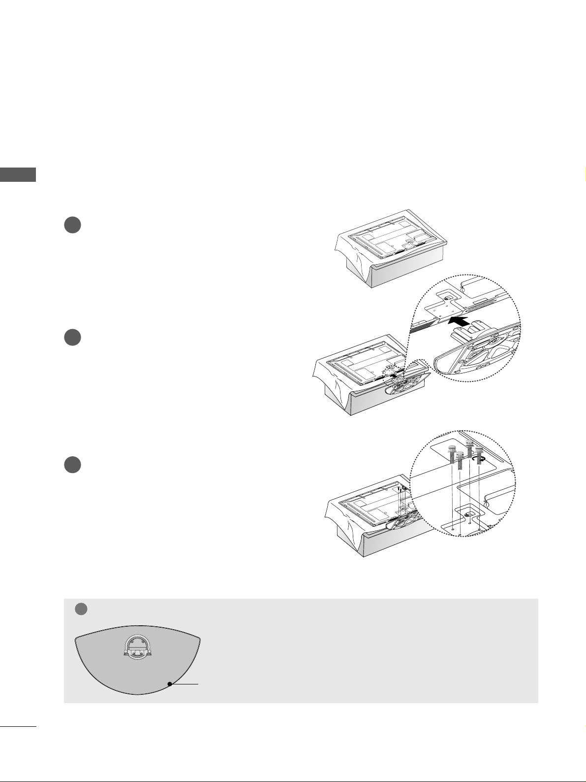
Stand Installation....................................................... 8
Careful installation advice.........................................9
Back Cover for Wire Arrangement....................... 10
Swivel Stand ..............................................................11
Not using the desk-type stand..............................11
Desktop Pedestal Installation.................................12
Wall Mount: Horizontal installation ......................12
ANTENNA CONNECTION.....................................13
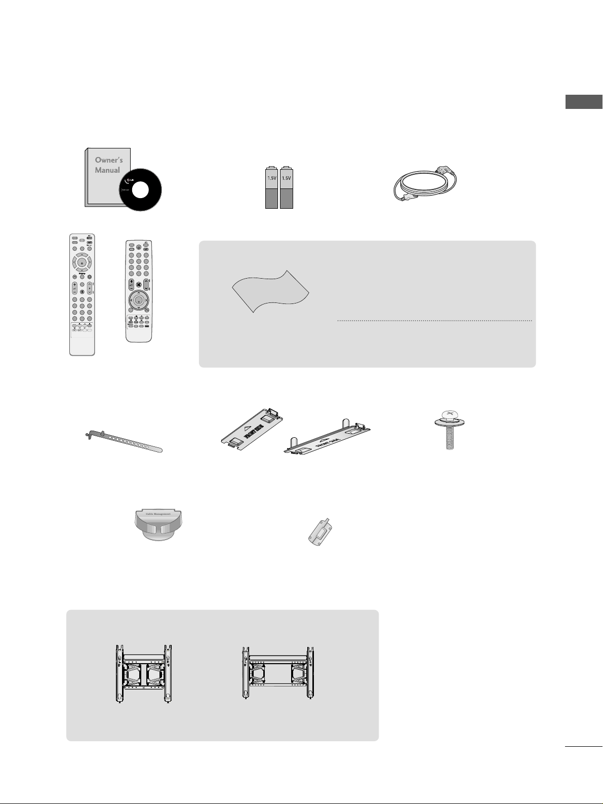
ACCESSORIES.......................................................1
O USE HE BLUE OO H
Bluetooth? .....................................................................50
Setting the Bluetooth ..................................................51
Set TV PIN......................................................................52
Bluetooth headset ......................................................53
Managing Registered Bluetooth device..................55
My Bluetooth Information .........................................56
Receiving photos through external
Bluetooth device...........................................................57
O USE HE USB DEVICE
When connecting a USB device...............................58
Photo list.........................................................................59
Music list.........................................................................63
Movie list ........................................................................66
DivX Registration Code .............................................70
Deactivation ..................................................................71
PIC URE CON ROL
Picture Size (Aspect Ratio Control........................72
Energy Saving ......................................................74
Power Saving ..................................................................74
Preset picture settings
Picture Mode-Preset .................................................75
Auto Colour Tone Control
(Warm/Medium/Cool .............................................76
Manual Picture Adjustment
Picture Mode-User option ......................................77
Picture Improvement Technology ............................78
Advanced - Black(Darkness Level...........................79
Advanced - Film Mode................................................80
Picture Reset ..................................................................81
Image Sticking Minimization (ISM Method .........82
Demo mode...............................................................83
Mode setting .............................................................84
Input LABEL....................................................................46
AV Mode .........................................................................47
key Lock...........................................................................48
Initializing (Reset to original factory settings .....49
EX ERNAL EQUIPMEN SE UP
HD Receiver Setup.................................................. 14
DVD Setup ................................................................ 16
VCR Setup................................................................. 18
Other A/V Source Setup....................................... 20
external stereo Setup ..............................................20
AV output setup ......................................................21
Usb in setup ............................................................ 21
PC Setup................................................................... 22
- Screen Setup for PC Mode........................... 24
WA CHING V / PROGRAMME CON ROL
REMOTE CONTROL KEY FUNCTIONS ................28
Turning on the TV ........................................................32
Programme Selection...................................................32
Volume Adjustment ................................................... 32
Quick Menu....................................................................33
On Screen Menus Selection and adjustment.......34
Auto programme tuning ............................................35
Manual programme Tuning ........................................36
Programme Edit ...........................................................38
SELECTING THE Programme List ............................40
favourite programme setup ........................................41
Input LIST .......................................................................42
SIMPLINK........................................................................43

CONTENTS
3
SOUND & LANGUAGE CON ROL
Auto Volume Leveler................................................85
Preset Sound Settings-Sound Mode ...................86
Sound Setting Adjustment -User Mode..............87
SRS TruSurround XT................................................87
Clear Voice II .............................................................88
Balance .......................................................................89
Selecting audio out .................................................90
Audio Reset................................................................91
TV Speakers On/ Off Setup ..................................92
I/II
Stereo/Dual Reception .......................................93
NICAM Reception ................................................94
Speaker Sound Output Selection......................94
On-Screen Menu Language Selection .................95
ELE EX
Switch on/off ...........................................................99
SIMPLE Text...............................................................99
TOP Text.....................................................................99
FASTEXT ..................................................................100
Special Teletext Functions....................................100
APPENDIX
Troubleshooting......................................................101
Maintenance............................................................103
Product Specifications ..........................................103
IR Codes...................................................................106
External Control Device Setup............................108
IME SE ING
Clock Setup...............................................................96
Auto on/off timer setting .......................................97
Sleep Timer setting..................................................98

4
PREPARATION
PREPARATION
FRONT PANEL CONTROLS
■
Here shown may differ from your TV
P
MENU
INPUT OK
42/50PQ3***
P
MENU
INPUT OK
IInntteelllliiggeenntt SSeennssoorr
Adjusts picture accord-
ing to the surrounding
conditions.
RReemmoottee CCoonnttrrooll
SSeennssoorr
PPoowweerr//SSttaannddbbyy IInnddiiccaattoorr
• Illuminates red in standby mode.
• Illuminates blue when the TV is
switched on.
P
MENU
INPUT OK
GGWhen the TV cannot be turned on with the remote control, press the main power button on the TV.
(When the power is turned off with the main power button on the TV, it will not be turned on with the
remote control.
CAU ION
P
MENU
INPUT OK
42/50PQ1***
P
MENU
INPUT OK
Power/Standby Indicator
•
Illuminates red in standby mode.
•
Illuminates blue when the TV is switched on.
Remote Control Sensor
P
MENUMENU
INPUTINPUT OKOK
INPUT MENU OK POWERVOLUME PROGRAMME
P
MENU
INPUT OK
INPUT MENU OK POWERVOLUME PROGRAMME

5
PREPARATION
Power/Standby Indicator
• Illuminates red in standby mode.
• The LED is off while the TV remains on.
42/50PQ6***, 42/50PS6***
MENU
INPUT
OK
P
P
PROGRAMME
VOLUME
OK
MENU
INPUT
POWER
IInntteelllliiggeennttSSeennssoorr
Adjusts picture according to
the surrounding conditions.
RReemmootteeCCoonnttrroollSSeennssoorr
Power/Standby Indicator
• Illuminates red in standby mode.
•
The LED is off while the TV remains on.
42/50PQ7***
IInntteelllliiggeennttSSeennssoorr
Adjusts picture
according to the sur-
rounding conditions.
RReemmootteeCCoonnttrrooll
SSeennssoorr
Power/Standby Indicator
• Illuminates red in standby mode.
•
The LED is off while the TV remains on.
50/60PS8*** IInntteelllliiggeennttSSeennssoorr
Adjusts picture
according to the sur-
rounding conditions.
RReemmootteeCCoonnttrrooll
SSeennssoorr

PREPARATION
6
PREPARATION
50/60PS4***
PROGRAMMEVOLUMEMENU OKINPUT
P
-+
OK
MENU
INPUT
P
-+
OK
MENU
INPUT
IInntteelllliiggeenntt SSeennssoorr
Adjusts picture according to
the surrounding conditions.
POWER
Remote Control Sensor
Power/Standby Indicator
• illuminates red in standby mode.
• illuminates green when the TV is
switched on.
P
- +
OK
OK
MENU
MENU
INPUT
INPUT

7
PREPARATION
BACK PANEL INFORMATION
A
Here shown may differ from your TV.
Power Cord Socket
This TV operates on an AC power. The voltage is
indicated on the Specifications page. Never
attempt to operate the TV on DC power.
HDMI Input
Connect an HDM signal to HDM N.
Or DV (V DEO)signal to HDM /DV (Except
4 /50PQ1***) port with DV to HDM cable.
RGB/DVI Audio Input
Connect the audio from a PC.
Component Input
Connect a component video/audio device to
these jacks.
RS- 3 C Input (CONTROL&SERVICE) Port
Connect to the RS-232C port on a PC.
This port is used for Service or Hotel mode.
RGB Input
Connect the output from a PC.
Audio/Video Input (AV IN1/ )
Connect audio/video output from an external
device to these jacks.
AV Output
Connect second TV or monitor to the AV OUT
socket on the TV.
Variable Audio Output
Connect an external amplifier or add a subwoofer
to your surround sound system.
Antenna Input
Connect RF antenna to this jack.
USB Input
Used for Music, Photo and Movie (Except
42/50PQ3***).
42/50PQ1*** : Service only
1 6
8
7
9
10
3
4
5
R
VARIABLE AUDIO OUT
( )
ANTENNA
IN
R
RGB(PC)
AUDIO IN
(RGB/DVI)
RL YP
B
PR
VIDEO
VIDEO
AUDIO
OUT
IN1
VARIABLE AUDIO OUTVARIABLE AUDIO OUT
2
1
COMPONENT IN
AV
HDMI
12
RS-232C IN
(CONTROL&SERVICE)
HDMI/DVI IN HDMI IN
Mono
()
AUDIO
--
1
3
6 7 985
4
AV IN 2
L/MONO
R
AUDIO
VIDEO
USB IN
VARIABLE AUDIO OUT
( )
AV IN 2
L/MONO
R
AUDIO
VIDEO
USB IN
HDMI IN3
ANTENNA
IN
RL YP
B
PR
VIDEO
AUDIO
COMPONENT IN
RS-232C IN
(CONTROL&SERVICE)
HDMI IN
VIDEO
IN
MONO
(
)
AUDIO
--
AV
USB IN
SERVICE ONLY
10 95
4
Only 4 /50PQ3***,
50/60PS4***
Except 4 /50PQ1***
7
7
10

PREPARATION
8
PREPARATION
STAND INSTALLATION (Except 60PS4***, 60PS8***)
■
Image shown may differ from your TV
■
When assembling the desk type stand, check whether the bolt is fully tightened. (If not tightened fully, the
product can tilt forward after the product installation. If you tighten the bolt with excessive force, the bolt can
deviate from abrasion of the tightening part of the bolt.
Carefully place the TV screen side down on a cush-
ioned surface to protect the screen from damage.
Assemble the TV as shown.
Fix the 4 bolts securely using the holes in
the back of the TV.
1
2
3
GGWhen assembling the stand, make sure to distinguish and assemble the
front and rear side of the stand correctly.
NO E
!
FRON

PREPARATION
9
CAREFUL INSTALLATION ADVICE
2
1
AYou should purchase necessary components to fix the TV safety and secure to the wall from the market.
APosition the TV close to the wall to avoid the possibility of it falling when pushed
AThe instructions shown below are a safer way to set up the TV, by fixing it to the wall, avoiding the possibility
of it falling forwards if pulled This will prevent the TV from falling forward and causing injury This will
also prevent the TV from damage Ensure that children do not climb or hang from the TV
NO E
!
G When moving the TV undo the cords first
G Use a platform or cabinet strong and large enough to support the size and weight of the TV
G To use the TV safely make sure that the height of the bracket on the wall and on the TV is the same
2
3
1
1
2
Use the eye-bolts or TV brackets/bolts to fix the product to the wall as shown in the picture.
(If your TV has bolts in the eyebolts, loosen then bolts.
* Insert the eye-bolts or TV brackets/bolts and tighten them securely in the upper holes.
Secure the wall brackets with the bolts on the wall. Match the height of the bracket that is mounted on the
wall.
3Use a sturdy rope to tie the product for alignment. It is safer to tie the rope so it becomes hori-
zontal between the wall and the product.

PREPARATION
10
PREPARATION
BACK COVER FOR WIRE ARRANGEMENT
■
Image shown may differ from your TV.
50/60PS4***, 42/50PQ7***, 50/60PS8*** only
After Connecting the cables as necessary, install
CABLE HOLDER as shown and bundle the cables.
To connect additional equipment, see the
EExxtteerrnnaall eeqquuiippmmeenntt SSeettuuppsection.
1
NO E
!
GGDo not use the CABLE MANAGEMEN CLIP to lift the TV.
- If the TV is dropped, you may be injured or the TV may be damaged.
Install the CCAABBLLEE MMAANNAAGGEEMMEENNTT CCLLIIPPas shown.
2
Hold the CCAABBLLEE MMAANNAAGGEEMMEENNTT CCLLIIPPwith both hands and pull it upward.
How to remove the cable management clip (50/60PS4***, 42/50PQ7***, 50/60PS8*** only )
After Connecting the cables as necessary,
install CABLE HOLDER as shown and bun-
dle the cables.
CABLE HOLDER
CABLE MANAGEMENT CLIP
CABLE HOLDER

11
PREPARATION
SWIVEL STAND
This feature is not available for all models.
After installing the TV, you can adjust the TV set man-
ually to the left or right direction by 20 degrees to
suit your viewing position
■
Here shown may differ from your TV.
When installing the wall-mounted unit, use the protection cover Insert the PPRROOTTEECCTTIIOONN CCOOVVEERRinto the TV
until clicking sound.
NOT USING THE DESK-TYPE STAND
Protection cover
Power Supply
Circuit breaker
EAR HING
Ensure that you connect the earth wire to prevent possible
electric shock. If grounding methods are not possible, have a
qualified electrician install a separate circuit breaker.
Do not try to earth the TV by connecting it to telephone
wires, lightening rods or gas pipes.

12
PREPARATION
PREPARATION
WALL MOUNT: HORIZONTAL INSTALLATION
AWe recommend the use of a LG Brand wall mounting
bracket when mounting the TV to a wall
AWe recommend that you purchase a wall mounting
bracket which supports VESA standard
ALG recommends that wall mounting be performed
by a qualified professional installer
4 inches 4 inches
4 inches
4 inches
4 inches
NO E
!
G Should Install wall mount on a solid wall perpen-
dicular to the floor
G Should use a special wall mount, if you want to
install it to ceiling or slanted wall
G The surface that wall mount is to be mounted on
should be of sufficient strength to support the
weight of TV set; e g concrete, natural rock, brick
and hollow block
G Installing screw type and length depends on the wall
mount used Further information, refer to the
instructions included with the mount
G LG is not liable for any accidents or damage to
property or TV due to incorrect installation:
- Where a non-compliant VESA wall mount is used
- Incorrect fastening of screws to surface which may
cause TV to fall and cause personal injury
- Not following the recommended Installation
method
4 inches 4 inches
4 inches
4 inches
DESKTOP PEDESTAL INSTALLATION
For adequate ventilation allow a clearance of 4” (10cm) all around the TV
AA
BB
Model VESA
(A *B Standard
Screw Quantity
42PQ1***
50PQ1***
42PQ3***
50PQ3***
50PS4***
60PS4***
42PQ6***
50PQ6***
42PS6***
50PS6***
42PQ7***
50PQ7***
50PS8***
60PS8***
400 * 400
400 * 400
400 * 400
400 * 400
400 * 400
600 * 400
400 * 400
400 * 400
400 * 400
400 * 400
400 * 400
400 * 400
400 * 400
600 * 400
M6
M6
M6
M6
M6
M8
M6
M6
M6
M6
M6
M6
M6
M8
4
4
4
4
4
4
4
4
4
4
4
4
4
4
AThe TV can be installed in various ways such as on a wall, or on a desktop etc
A The TV is designed to be mounted horizontally

13
PREPARATION
ANTENNA
IN
R
VARIABLE AUDIO OUT
( )
ANTENNA
IN
R
VARIABLE AUDIO OUT
( )
ANTENNA CONNECTION
R
VARIABLE AUDIO OUT
( )
■For optimum picture quality, adjust antenna direction.
■An antenna cable and converter are not supplied.
■To prevent damage do not connect to the mains outlet until all connections are made between the devices.
Multi-family Dwellings/Apartments
(Connect to wall antenna socket)
Single-family Dwellings /Houses
(Connect to wall jack for outdoor antenna)
Outdoor
Antenna
(VHF, UHF)
Wall
Antenna
Socket
RF Coaxial Wire (75 ohm)
Antenna
UHF
Signal
Amplifier
VHF
■In poor signal areas, to achieve better picture quality it may be necessary to install a signal amplifier to the
antenna as shown above.
■If signal needs to be split for two TVs,use an antenna signal splitter for connection.
Install the power plug closely
Use of ferrite core (This feature is not available for all models )
Ferrite core can be used to reduce the electromagnetic
wave when connecting the power cord
The closer the location of the ferrite core to the power
plug, the better it is

14
EXTERNAL EQUIPMENT SETUP
HD RECEIVER SETUP
■To avoid damaging any equipment, never plug in any power cords until you have finished connecting all equipment
■
Here shown may differ from your TV.
Connecting with a component cable
Signal
480i/576i
480p/576p
720p/1080i
1080 p
Component
O
O
O
O
(50/60Hz only
HDMI
X
O
O
O
(24Hz/30Hz/50Hz/60Hz
Connect the video outputs (Y, PB, PRof the digital set-
top box to the CCOOMMPPOONNEENNTT IINN VVIIDDEEOOjacks on
the TV.
Connect the audio output of the digital set-top box to
the CCOOMMPPOONNEENNTT IINN AAUUDDIIOOjacks on the TV.
Turn on the digital set-top box.
(Refer to the owner’s manual for the digital set-top
box.
Select CCoommppoonneenntt11 input source using the IINNPPUUTT
button on the remote control.
If connected to CCOOMMPPOONNEENNTT IINN22, select
CCoommppoonneenntt22 input source(Except 42/50PQ1*** .
2
3
4
1
HDMI
2
HDMI IN
RGB(PC)
AN
AUDIO IN
(RGB/DVI)
AV
VIDEO
Mono
()
AUDIO
--
VARIABLE AUDIO OUT
IN1
OUT
COMPONENT IN
L R Y P
B
P
R
( )
1
2
VIDEO
AUDIO
( )
RL YP
B
P
R
1
2
RL YP
B
P
R
VIDEO
AUDIO
COMPONENT IN
( )
ANTENNA
IN
L R Y P
B
P
R
( )
1
2
Only 42/50PQ1***

15
EXTERNAL EQUIPMENT SETUP
Connecting a set-top box with an HDMI cable
Connecting with an HDMI to DVI cable
(Except 42/50PQ1***
Connect the HDMI output of the digital set-top box to
the HHDDMMII//DDVVII IINN 11(or HHDDMMII IINN(Only
42/50PQ1*** ,,HHDDMMII IINN 22 (Except 42/50PQ1*** or
HHDDMMII IINN 33(Except 42/50PQ1***,42/50PQ3***,
50/60PS4*** jack on the TV.
Select HHDDMMII11(or HHDDMMII (Only 42/50PQ1*** ,,
HHDDMMII22(Except 42/50PQ1*** or HHDDMMII33(Except
42/50PQ1***, 42/50PQ3***, 50/60PS4*** input
source using the IINNPPUUTTbutton on the remote control.
Turn on the digital set-top box.
(Refer to the owner’s manual for the digital set-top
box.
2
3
1
Connect the DVI output of the digital set-top box to the
HHDDMMII//DDVVII IINN 11 jack on the TV.
Connect the audio output of the digital set-top box to
the AAUUDDIIOO IINN((RRGGBB//DDVVII jack on the TV.
Turn on the digital set-top box. (Refer to the owner’s
manual for the digital set-top box.
Select HHDDMMII11input source using the IINNPPUUTTbutton
on the remote control.
2
3
4
1
( )
( )
RS-232C IN
(CONTROL&SERVICE)
RGB(PC)
A
VIDEO
HDMI
HDMI/DVI IN
1
HDMI IN
HDMI-DTV OUTPUT
2
Mono
()
AUDIO
--
1
( )
RS-232C IN
(CONTROL&SERVICE)
HDMI IN
( )
USB IN
SERVICE ONLY
HDMI-DTV OUTPUT
1
( )
L R
DVI-DTV OUTPUT
RS-232C IN
(CONTROL&SERVICE)
RGB(PC)
AV
VIDEO
Mono
()
AUDIO
--
VARIABLE AUDIO OUT
IN1
OUT
HDMI
HDMI/DVI IN
1
HDMI IN
AUDIO IN
(RGB/DVI)
2
( )
1
2
GGCheck that your HDMI cable is version 1.3 or higher.
If the HDMI cables don’t support HDMI version 1.3, flicker-
ing or no screen display can result. Please use the latest
cables that support at least HDMI version 1.3.
GGHDMI mode supports PCM audio format only.
GGAudio format was reseted to Dolby/DTS/Bitstrem in DVD
Player or STB, it should be changed to PCM.
GGWe recommed using under 10m of the HDMI cable.
When using over the length, connect a amplifier or repeater.
NO E
!
GGHDMI mode supports PCM audio format only.
GGAudio format was reseted to Dolby/DTS/Bitstrem in DVD
Player or STB, it should be changed to PCM.
GGWe recommed using under 10m of the HDMI cable.
When using over the length, connect a amplifier or repeater.
NO E
!
Only 42/50PQ1***

16
EXTERNAL EQUIPMENT SETUP
DVD SETUP
Connecting with a component cable
Component Input ports
To achieve better picture quality, connect a DVD player to the
component input ports as shown below
Component ports on the TV
YPBPR
Video output ports
on DVD player
Y
Y
Y
Y
PB
B-Y
Cb
Pb
PR
R-Y
Cr
Pr
Connect the video outputs (Y, PB, PRof the DVD to
the CCOOMMPPOONNEENNTT IINN VVIIDDEEOOjacks on the TV.
Connect the audio outputs of the DVD to the CCOOMM--
PPOONNEENNTT IINN AAUUDDIIOOjacks on the TV.
Turn on the DVD player, insert a DVD.
Select CCoommppoonneenntt11 input source using the IINNPPUUTT
button on the remote control.
If connected to CCOOMMPPOONNEENNTT IINN22, select
CCoommppoonneenntt 22 input source (Except 42/50PQ1*** .
Refer to the DVD player's manual for operating
instructions.
2
3
4
5
1
RL YP
B
P
R
VIDEO
AUDIO
COMPONENT IN
( )
ANTENNA
IN
L R Y P
B
P
R
( )
1
2
Only 42/50PQ1***
HDMI
2
HDMI IN
RGB(PC)
AN
AUDIO IN
(RGB/DVI)
AV
VIDEO
Mono
()
AUDIO
--
VARIABLE AUDIO OUT
IN1
OUT
COMPONENT IN
L R Y P
B
P
R
( )
1
2
VIDEO
AUDIO
( )
RL YP
B
P
R
1
2

17
EXTERNAL EQUIPMENT SETUP
Connecting with a HDMI cable
Connect the HDMI output of the DVD to the
HHDDMMII//DDVVII IINN 11(or HHDDMMII IINN(Only 42/50PQ1*** ,,
HHDDMMII IINN 22(Except 42/50PQ1*** or HHDDMMII IINN
33(Except 42/50PQ1***, 42/50PQ3***, 50/60PS4***
jack on the TV.
Select HHDDMMII11(or HHDDMMII (Only 42/50PQ1*** ,,
HHDDMMII22(Except 42/50PQ1*** or HHDDMMII33(Except
42/50PQ1***, 42/50PQ3***, 50/60PS4*** input
source using the IINNPPUUTTbutton on the remote control.
Refer to the DVD player's manual for operating instruc-
tions.
2
3
1
GGThe TV can receive video and audio signals simultaneously
when using a HDMI cable.
GGIf the DVD does not support Auto HDMI, you must set the
output resolution appropriately.
GGCheck that your HDMI cable is version 1.3 or higher.
If the HDMI cables don’t support HDMI version 1.3, flicker-
ing or no screen display can result. Please use the latest
cables that support at least HDMI version 1.3.
GGHDMI mode supports PCM audio format only.
GGAudio format was reseted to Dolby/DTS/Bitstrem in DVD
Player or STB, it should be changed to PCM.
GGWe recommed using under 10m of the HDMI cable.
When using over the length, connect a amplifier or repeater.
NO E
!
RS-232C IN
(CONTROL
&SERVICE
)
RGB(PC)
A
VIDEO
Mono
()
AUDIO
--
HDMI
HDMI/DVI IN HDMI IN
12
HDMI-DVD OUTPUT
1
RS-232C IN
(CONTROL&SERVICE)
HDMI IN
( )
USB IN
SERVICE ONLY
HDMI-DVD OUTPUT
1
Only 42/50PQ1***

18
EXTERNAL EQUIPMENT SETUP
VCR SETUP
■To avoid picture noise (interference), allow adequate distance between the VCR and TV
C
2
AUDIO
ANTENNA
IN
L R
S-VIDEO VIDEO
OUTPUT
SWITCH
ANT IN
ANT OUT
( )
( )
Wall Jack
Antenna
1
2
Connecting with a RF Cable
Connect the AANNTT OOUUTTsocket of the VCR to the AANNTTEENNNNAA IINNsocket on the TV.
Connect the antenna cable to the AANNTT IINNsocket of the VCR.
Press the PPLLAAYYbutton on the VCR and match the appropriate programme between the TV and VCR for
viewing.
2
3
1
This manual suits for next models
15
Table of contents
Other LG Plasma TV manuals
Popular Plasma TV manuals by other brands

Panasonic
Panasonic VIERA TC-P50G20 operating instructions

Panasonic
Panasonic TH-42PA25U/P Service manual

Panasonic
Panasonic Viera TH-37PX60E operating instructions

Panasonic
Panasonic THC42HD18A - 42" PLASMA TV Service manual

Panasonic
Panasonic TH-65/58/50PZ750U Service hints

Panasonic
Panasonic Viera TH-37PV60E Gebruiksaanwijzing