- 10 -
ADJUSTMENT INSTRUCTIONS
1. Application Object
These instructions apply to the MF-056A Chassis.
2. Specification
(1) Because this is not a hot chassis, it is not necessary to use
an isolation transformer. However, the use of isolation
transformer will help protect test instrument.
(2) Adjustment must be done in the correct order.
(3) The adjustment must be performed in the circumstance of
25±5°C of temperature and 65±10% of relative humidity if
there is no specific designation.
(4) The input voltage of the receiver must keep 100-220V,
50/60Hz.
(5) The receiver must be operated for about 15 minutes prior
to the adjustment.
OAfter RGB Full white HEAT-RUN Mode, the receiver must
be operated prior to adjustment.
OEnter into HEAT-RUN MODE
1) Press the POWER ON KEY on R/C for adjustment.
2) OSD display and screen display 100% full WHITE
PATTERN.
[Set is activated HEAT-RUN without signal generator in
this mode.
[Single color pattern(RED/BLUE/GREEN) of HEAT-RUN
mode uses to check PANEL.
Caution) If you turn on a still screen more than 20 minutes
(Especially digital pattern, cross hatch pattern), after
image may be occur in the black level part of the
screen.
3. Channel memory
3-1. Setting up the LGIDS
1) Install the LGIDS. (idsinst.exe)
2) After installation, restart your PC.
3) Extract [files.zip] to folder [c:\LGIDS\files].
4) Start LGIDS.
3-2. Channel memory Method
1) Select “PDP” and “Hurricane” on Model dialog. And check
your connection in Communication dialog. (If your
connection is ‘NG’, then set your PORT(COM1,2,3,...)
correctly.)
2) Connect RS-232C cable and turn on the power.
(If your connection has completed, you can see “Ready”.)
[If your set is not an end products but only a board, you
have to make your board to Stand-by state (LED_R). And
you have to Download in Stand_by power state.
3) Select proper CH_memory file(*.nvm) for each model at
[NVRAM Download] $ [Write Batch]
Next, select proper binary file(*.bin) including the CH
information for each model at [NVRAM File].
4) Click the [Download] button.
It means the completion of the CH memory download if all
items show ‘OK’ and Status is changed by ‘PASS’ at the
lower right corner of the window.
5) If you want to check whether the CH information is
memorized correctly or not, click the [Verify] button.
And then compare NVRAM File(*.bin) with the CH
information downloaded.
3-3 Sub program download
1) Select “PDP” and “Hurricane” on Model dialog. And check
your connection in Communication dialog. (If your
connection is ‘NG’, then set your PORT(COM1,2,3,...)
correctly.)
(Fig. 1)
(Fig. 3)
(Fig. 3-1)


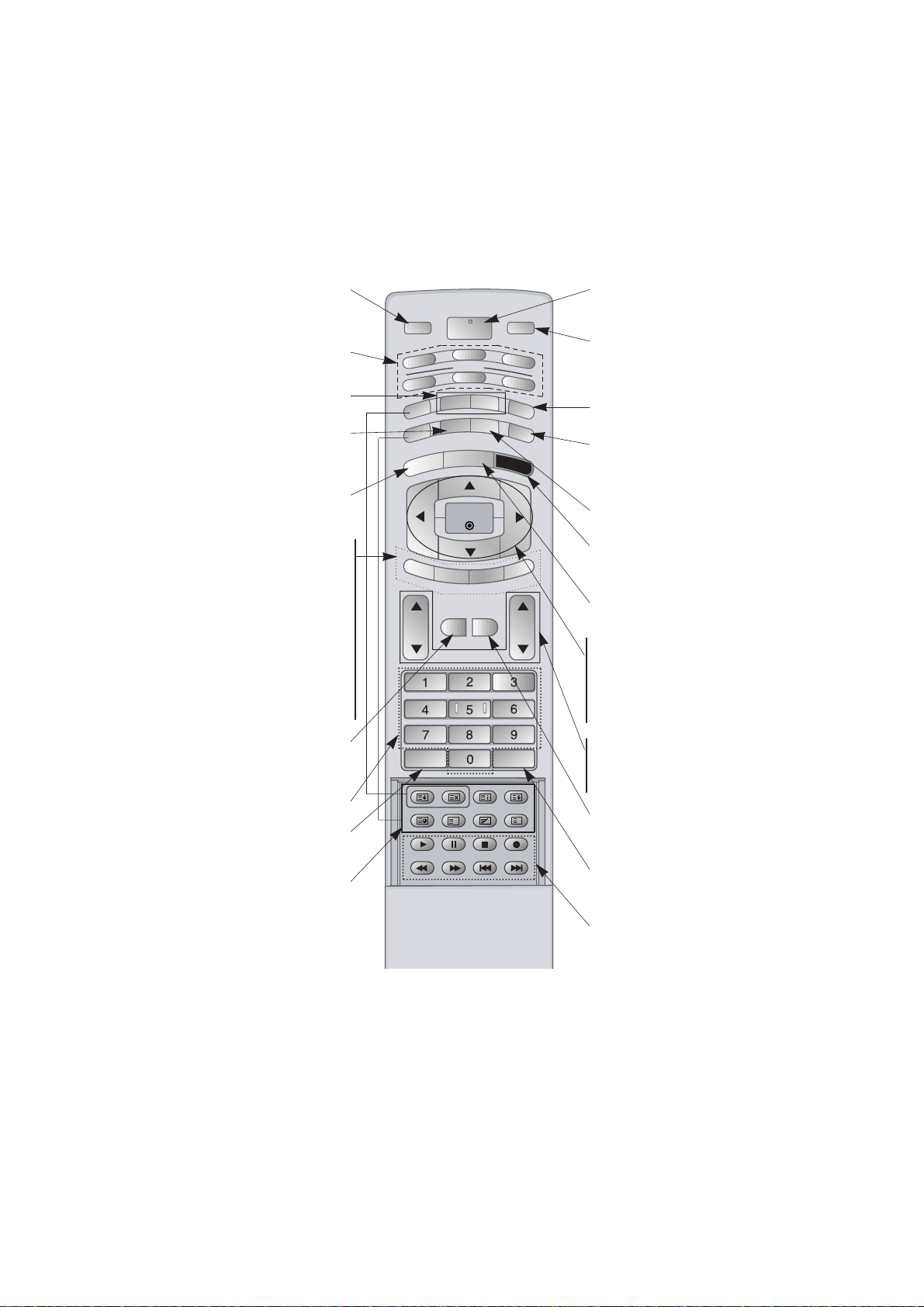
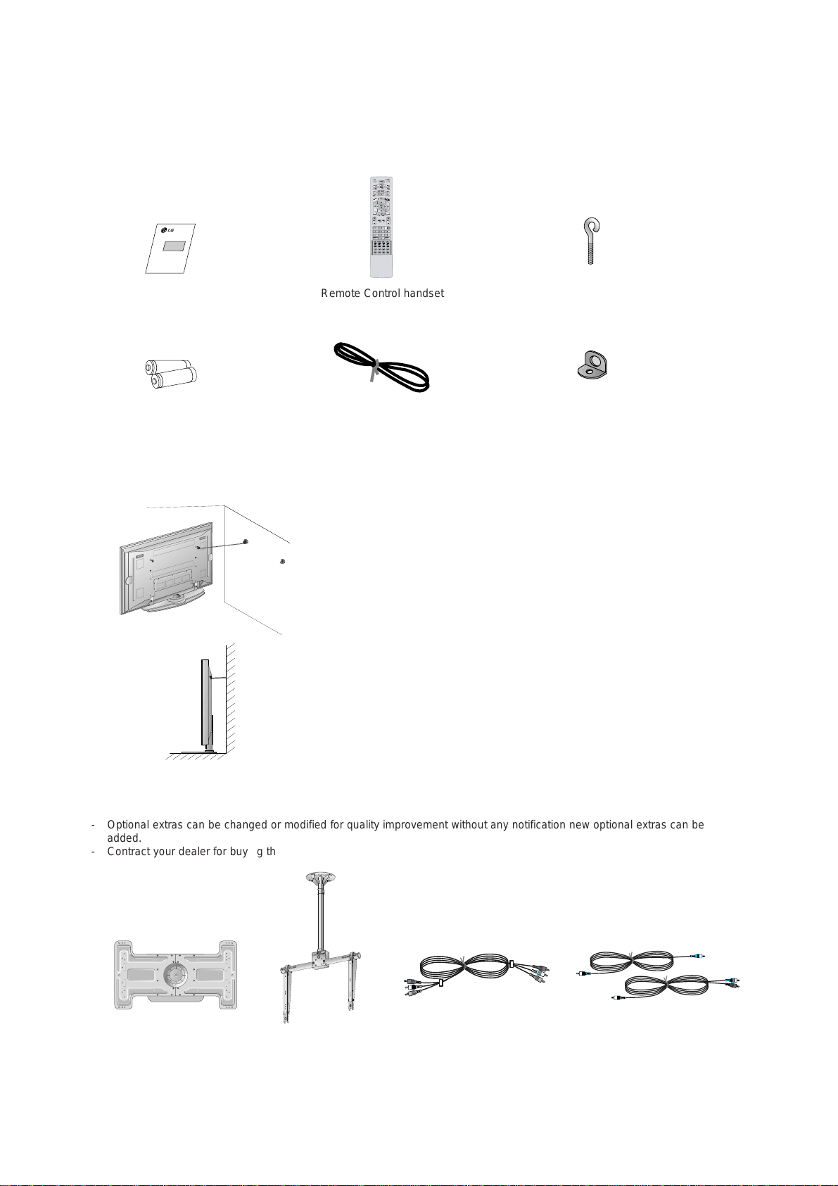
 User manual")