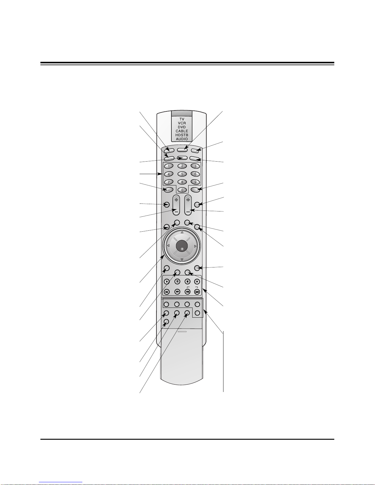
LG DU-42PZ60H User manual

PLASMA TV
SERVICE MANUAL
CAUTION
BEFORE SERVICING THE CHASSIS,
READ THE SAFETY PRECAUTIONS IN THIS MANUAL.
CHASSIS : AF-03BB
MODEL : DU-42PZ60/H
website:http://biz.LGservice.com
e-mail:http://www.LGEservice.com/techsup.html

- 2 -
SAFETY PRECAUTIONS
Many electrical and mechanical parts in this chassis have special safety-related characteristics. These parts are identified by in
the Schematic Diagram and Replacement Parts List.
It is essential that these special safety parts should be replaced with the same components as recommended in this manual to
prevent X-RADIATION, Shock, Fire, or other Hazards.
Do not modify the original design without permission of manufacturer.
General Guidance
An lsolation Transformer should always be used during
the servicing of a receiver whose chassis is not isolated from
the AC power line. Use a transformer of adequate power rating
as this protects the technician from accidents resulting in
personal injury from electrical shocks.
It will also protect the receiver and it's components from being
damaged by accidental shorts of the circuitary that may be
inadvertently introduced during the service operation.
If any fuse (or Fusible Resistor) in this monitor is blown, replace
it with the specified.
When replacing a high wattage resistor (Oxide Metal Film
Resistor, over 1W), keep the resistor 10mm away from PCB.
Keep wires away from high voltage or high temperature parts.
Due to high vacuum and large surface area of picture tube,
extreme care should be used in handling the Picture Tube.
Do not lift the Picture tube by it's Neck.
Leakage Current Cold Check(Antenna Cold Check)
With the instrument AC plug removed from AC source,
connect an electrical jumper across the two AC plug prongs.
Place the AC switch in the on positioin, connect one lead of
ohm-meter to the AC plug prongs tied together and touch other
ohm-meter lead in turn to each exposed metallic parts such as
antenna terminals, phone jacks, etc.
If the exposed metallic part has a return path to the chassis, the
measured resistance should be between 1MΩ and 5.2MΩ.
When the exposed metal has no return path to the chassis the
reading must be infinite.
An other abnormality exists that must be corrected before the
receiver is returned to the customer.
Leakage Current Hot Check (See below Figure)
Plug the AC cord directly into the AC outlet.
Do not use a line Isolation Transformer during this check.
Connect 1.5K/10watt resistor in parallel with a 0.15uF capacitor
between a known good earth ground (Water Pipe, Conduit, etc.)
and the exposed metallic parts.
Measure the AC voltage across the resistor using AC
voltmeter with 1000 ohms/volt or more sensitivity.
Reverse plug the AC cord into the AC outlet and repeat AC
voltage measurements for each esposed metallic part. Any
voltage measured must not exceed 0.75 volt RMS which is
corresponds to 0.5mA.
In case any measurement is out of the limits sepcified, there is
possibility of shock hazard and the set must be checked and
repaired before it is returned to the customer.
Leakage Current Hot Check circuit
1.5 Kohm/10W
To Instrument's
exposed
METALLIC PARTS
Good Earth Ground
such as WATER PIPE,
CONDUIT etc.
AC Volt-meter
IMPORTANT SAFETY NOTICE
0.15uF

- 3 -
DESCRIPTION OF CONTROLS...........................................4
SPECIFICATIONS.................................................................7
ADJUSTMENT INSTRUCTION.............................................8
PRINTED CIRCUIT BOARD ...............................................11
BLOCK DIAGRAM...............................................................17
EXPLODED VIEW...............................................................18
EXPLODED VIEW PARTS LIST.........................................19
REPLACEMENT PARTS LIST............................................20
SCHEMATIC DIAGRAM..........................................................
TABLE OF CONTENTS

- 4 -
Controls
Controls
TV/VIDEO
ON/OFF S-VIDEO
A/V INPUT 2
VIDEO AUDIO R
L/MONO
MENU VOL CH
TV/VIDEO MENU VOL CH
ON/OFF S-VIDEO VIDEO AUDIO
L/MONO
A/VINPUT 2
R
Power Button
S-VIDEO Input
A connection available to provide better
picture quality than the video input.
VIDEO Input
Connects the video signal
from a video device.
AUDIO Input
Use to connect to hear
stereo sound from an
external device.
TV/VIDEO Button
VOLUME (FF,GG) Buttons
Power Standby Indicator
Illuminates red in standby mode,
Illuminates green when the TV is
turned on.
- This is a simplified representation of front panel.
Here shown may be somewhat different from your TV.
- This manual explains the features available on the DU-50PZ60/70 series TVs.
Remote Control Sensor
CHANNEL (EE, DD) Buttons
MENU Button
Front Panel Controls
DESCRIPTION OF CONTROLS

- 5 -
Connection Options
Connection Options
RGB INPUT
Antenna1 Antenna 2
AUDIO INPUT
DVI INPUT S-VIDEO REMOTE
CONTROL AC INPUT
EXTERNAL SPEAKER
AUDIO INPUT
AUDIO VIDEO
VIDEO INPUT
DIGITAL AUDIO
(OPTICAL)
COMPONENT 2
MONITOR
OUTPUT
A/V
INPUT1
(MONO)
DVD
/DTV
INPUT
COMPONENT 1
DVI
INPUT
R L R L RL
COMPONENT1
INPUT
OUTPUT
RS-232C INPUT
(CONTROL/SERVICE)
Back Connection Panel
Antenna 1-2 Inputs
Connect cable or antenna
signals to the TV, either
directly or through your
cable box. For DTV use
Antenna 2 only.
RGB Input/Audio Input/DVI Input
Connect the monitor output connector from
a PC to the appropriate input port.
Digital Audio (DVI: Digital Visual
Interface/Component1) Input/
Digital Audio Output
Connect digital audio from various types
of equipment. Note: In standby mode,
these ports will not work.
Audio/Video Input 1
Connect audio/video output from an
external device to these jacks.
DVD/DTV Input (Component 1-2)
Connect a component video/audio device to these jacks.
Monitor Output
Connect a second TV or
Monitor.
Remote Control Port
Connect your wired remote
control here.
S-Video Input
Connect S-Video out from an S-VIDEO
device to the S-VIDEO input.
External Speaker (8 ohm Output)
Connect to optional external speaker(s).
* For further information, refer to ‘Speaker &
Speaker Stand’ manual.
Power Cord Socket
This TV operates on an AC power. The voltage is indi-
cated on the Specifications page. Never attempt to oper-
ate the TV on DC power.
- This manual explains the features available on the DU-50PZ60/70 series TVs.
DESCRIPTION OF CONTROLS

- 6 -
DESCRIPTION OF CONTROLS
-When using the remote control, aim it at the remote control sensor on the TV.
LIGHT
TV/VIDEO
MODE
COMP/RGB/DVI
MUTE SURF
VOL CH
INFO
SAP RATIO
CC
MENU
SOUND VIDEO
EXIT
PLAY PAUSE STOP RECORD
PIP PIPCH- PIPCH+ PIPINPUT
FREEZE
ADJUST
OK
ZOOM SIGNAL SWAP
REW FF SKIP
POWER
TIMER
FLASHBK
LIGHT
Illuminates the remote control buttons.
TV/VIDEO
Selects: DTV, Analog, Video1-2,
Component 1-2, RGB-DTV (or RGB-PC),
DVI-DTV (or DVI-PC) input sources.
COMP/RGB/DVI
Selects: Component 1-2, RGB-DTV (or RGB-
PC), DVI-DTV (or DVI-PC) input sources.
NUMBER buttons
DASH
Used to enter a program number for multiple
program channels such as 2—1,2—2,etc.
MUTE
Switches the sound on or off.
VCR/DVD BUTTONS
Control some video cassette recorders or
DVD player ("RECORD" button is not avail-
able for DVD player).
RATIO
Changes the aspect ratio.
MODE
Selects the remote operating mode: TV,
VCR, DVD, CABLE, HDSTB or AUDIO.
Select other operating modes, for the
remote to operate external devices.
POWER
Turns your TV or any other programmed
equipment on or off, depending on mode.
TIMER
Lets you select the amount of time before
your TV turns itself off automatically.
SURF
Use to scroll the Surf channel list.
CC
Select a closed caption:
Off, EZ Mute, and On.
FLASHBK
Tunes to the last channel viewed.
THUMBSTICK (Up/Down/Left/Right/OK)
Allows you to navigate the on-screen
menus and adjust the system settings to
your preference.
CHANNEL UP/DOWN
Selects available channels found
with EZ scan.
EXIT
Clears all on-screen displays and returns to
TV viewing from any menu.
VIDEO
Adjusts the factory preset picture according
to the room.
VOLUME UP/DOWN
Increases/decreases the sound level.
SAP
Selects MTS sound: Mono, Stereo, and SAP.
Change the audio language in DTV mode.
MENU
Brings up the main menu to the screen.
INFO
When you watch the TV, displays information
on top of the screen. Not available in
Component 1-2, RGB and DVI mode.
SOUND
Selects the sound appropriate
for the program's character. PIP
Switches between PIP, POP (Picture-out-of-
Picture) and Twin picture modes.
PIPCH-/PIPCH+
Changes to next higher/lower PIP channel.
PIP INPUT
Selects the input source for the sub picture.
SWAP
Exchanges the PIP/main images.
FREEZE
Freezes the currently-viewed picture. Main
picture is frozen in PIP/Twin picturre mode.
ADJUST
Adjusts screen position, clock, and
phase in PC mode.
ZOOM
Enlarges the main picture size.
SIGNAL
Displays the digital signal strength.
Remote Control Key Functions

- 7 -
•The specifications shown above may be changed without prior notice for quality improvement.
MODELS
AC100-240V ~ 50/60Hz
NTSC-M, ATSC
VHF 2 ~ 13, UHF 14 ~ 69, CATV 1 ~ 125, CADTV 1 ~ 135. DTV 2 ~ 69
75 Ω
1024 x 768 (Dot) 1366 x 768 (Dot)
16,770,000 (256 steps of each R, G and B)
32 ~ 104°F (0 ~ 40°C)
Less than 80%
6561 feet (2000m)
41 / 1040
27.5 / 699.5
3.7 / 95
76.1 / 34.5
41 / 1040
26.4 / 669.5
3.7 / 95
73.4 / 33.3
48.2 / 1225
30.6 / 778
3.85 / 98
101.2 / 45.9
48.3 / 1226.2
30.6 / 778
3.9 / 99
98.1 / 44.5
Width (inches / mm)
Height (inches / mm)
Depth (inches / mm)
Weight (pounds / kg)
Power requirement
Television System
Program Coverage
External Antenna Impedance
Resolution
Color
Operating Temperature Range
Operating Humidity Range
Maximum Elevation
DU-42PZ60/42PZ60A
/42PZ60B/42PZ60C
/42PZ60K/42PZ60R
/42PZ60S
DU-42PZ60H/42PZ60HA
/42PZ60HB/42PZ60HC
/42PZ60HK/42PZ60HR
/42PZ60HS
DU-50PZ60/50PZ60A
/50PZ60B/50PZ60C
/50PZ60K/50PZ60R
/50PZ60S
DU-50PZ60H/50PZ60HA
/50PZ60HB/50PZ60HC
/50PZ60HK/50PZ60HR
/50PZ60HS
DU-42PZ70/42PZ70A
/42PZ70B/42PZ70C
/42PZ70K/42PZ70R
/42PZ70S
DU-42PZ70H/42PZ70HA
/42PZ70HB/42PZ70HC
/42PZ70HK/42PZ70HR
/42PZ70HS
DU-50PZ70/50PZ70A
/50PZ70B/50PZ70C
/50PZ70K/50PZ70R
/50PZ70S
DU-50PZ70H/50PZ70HA
/50PZ70HB/50PZ70HC
/50PZ70HK/50PZ70HR
/50PZ70HS
SPECIFICATIONS

1. Application Object
These instructions are applied to all of the PDP TV, AF-03BA/BB.
2. Notes
(1) Because this is not a hot chassis, it is not necessary to use
an isolation transformer. However, the use of isolation
transformer will help protect test instrument.
(2) Adjustment must be done in the correct order.
(3) The adjustment must be performed in the circumstance of
25±5°C of temperature and 65±10% of relative humidity if
there is no specific designation.
(4) The input voltage of the receiver must keep 100~240V,
50/60Hz in adjusting.
(5) The receiver must be operated for about 15 minutes prior
to the adjustment.
1) After receiving 100% white pattern(06CH), the receiver
must be operate prior to adjustment. (Or 3. White
Pattern condition in EZ - Adjust)
2) Enter into White Pattern
- Enter the Ez - Adjust by pressing ADJ Key on R/C for
adjustment.
- Select the 3. White Pattern using CH +/- Key and
press the Enter(Y) Key.
Display the 100% Full White Pattern.
[Set is activated HEAT-RUN without signal generator in
this mode.
If you turn on a still screen more than 20 minutes (Especially
Digital pattern(13 CH), Cross Hatch Pattern), a afterimage may
be occur in the black level part of the screen.
3. EPLD Download
(1) Test Equipment: Jig for PC, download
(2) Connect the power of VSC B/D.
(3) Execute download program(Flash Loader) of PC.
(4) After executing execution hot key (Programmer), icon click
(5) End after confirming
Each PCB Assy must be checked by Check JIG Set before
assembly. (Especially, be careful Power PCB Assy which can
cause fatal Damage to PDP Module.)
4. POWER PCB Assy Voltage
Adjustment (Va, Vs Voltage Adjustment)
4-1 Test Equipment :D.M.M 1EA
4-2 Connection Diagram for Measuring
Refer to Fig 2.
4-3 Adjustment Method
(1) Va Adjustment
1) Connect + terminal of D.M.M to Va pin of P805 and
connect – terminal to GND pin of P805.
2) After turning the RV601, voltage of D.M.M adjustment as
same as Va voltage which on label of panel Right/Top.
(Deviation : ±0.5V)
(2) Vs adjustment
1) Connect + terminal of D.M.M to Vs pin of P805 and connect
– terminal to GND pin of P805.
2) After turning the RV401, voltage of D.M.M adjustment as
same as Vs voltage which on label of panel Right/Top.
(Deviation : ±0.5V)
- 8 -
ADJUSTMENT INSTRUCTIONS
PC VSC
B/D
<Fig 1> Connection Diagram of EPLD Download
<Fig 2> Connection Diagram of Power Adjustment for Measuring

- 9 -
5. AD9883A-Set Adjustment
5-1 Synopsis
AD9883A-Set adjustment to set the black level and the Gain
of optimum with an automatic movement from the analog =>
digital converter and RGB revises a deviation a function for it
is.
5-2 Test Equipment
R/C for adjustment, 801GF(802B, 802F, 802R) Pattern
Generator
(720P The Vertical 100% Color Bar Pattern output will be
possible and the output level will accurately have to be
revised with 0.7±0.1Vp-p)
5-3 Adjustment
(1) Input the 100% Vertical Color Bar Pattern(TVBAR_100) of
720P Mode possible Component input support, select the
Component1 or Component2 an input selection and select
the Clear image.
(2) After signal receiving above 1 second, press the ADJ Key
on R/C for adjustment enter the ‘Ez - Adjust’ and select the
‘5. AD9883A-Set’.
Pressing the + Key adjust with automatic movement.
(3) When the adjustment is over in the normality and the
message which is a ‘AD9883 - Set’ becomes the display
and the case which has not become the normality the
message which is a ‘AD9883A set error’ becomes the
display.
(4) Readjust after confirming the case Pattern or adjustment
condition where the adjustment had not become the
normality.
(5) After adjustment complete, exit the adjustment mode by
press ADJ KEY.
6. Adjustment of White Balance
6-1. Required Equipment
(1) Color analyzer (CA-100 or same product)
(2) Automatic adjustor (with automatic adjustment hour
necessity and the RS-232C communication being possible)
(3) AV Pattern Generator
6-2. Connection Diagram of Equipment for
Measuring (Automatic Adjustment)
6-3. Adjustment of White Balance
O
Operate the Zero-calibration of the CA-100, then stick sensor
to PDP module surface when you adjust.
O
For manual adjustment, it is also possible by the following
sequence.
(1) Enter the ‘Ez - Adjust’ by pressing ADJ KEY on R/C for
adjustment.
(2) Select the 3. WHITE PATTERN using CH +/- Key and HEAT
RUN above 15 minutes by pressing the ENTER Key.
(3) Receive the Window pattern signal from AV Pattern
Generator. (AV Input)
(4) Set Picture condition to “CLEAR Image”.
(5) After stick sensor to center of screen, select the ‘2. White-
Balance’ of ‘Ez - Adjust’ by pressing the ADJ KEY n R/C for
adjustment. And enter adjustment mode by pressing the Right
KEY(
G
) .
(6) Adjust the Hight Light using R Gain/B Gain and adjust the
Low Light using G Cut/B Cut.
(7) Adjust using Volume +/- KEY.
(G Gain : 120 / R Cut : 63)
Hight Light : 150±10 Cd
Low Light : 5±2 Cd
X; 0.280±0.003
Y; 0.290±0.003
Color temperature: 10,000°K±500°K
(8) After adjustment complete, move to Ez - Adjust screen by
pressing the ENTER(Y) KEY. And exit the adjustment mode
by press ADJ KEY.
ADJUSTMENT INSTRUCTIONS
<Fig 3> Adjustment Pattern : 720P Vertical Color Bar
High Light Adjustment
Low Light Adjustment
Signal Input
<Fig 4> Connection Diagram of Automatic Adjustment

- 10 -
6-4. Main/Sub Contrast Adjustment
Main/Sub contrast adjustment is adjustment reduces the
contrast difference of Main/Sub screen in PIP/POP/SPLIT
Screen.
(1) After signal receiving above 1 second, press the ADJ KEY
on R/C for adjustment enter the ‘Ez - Adjust’ and select the
‘2. VPX3226’.
Enter adjustment mode by pressing the Right KEY(
G
).
(2) When enter adjustment mode, becomes the image TV
6CH SPLIT Screen with automatic movement and appear
below window.
(3) The contour of “US 6CH” letter of left Main screen is most
clear and it is clear, 1.Contrast (Main) after adjusting first,
in order for right side Sub screen to contrast to become the
left Main screen to contrast with same, 2.Contrast (Sub) it
adjust. This time adjust using the volume +/- Key.
(4) After adjustment complete, exit the adjustment mode by
press ADJ KEY.
ADJUSTMENT INSTRUCTIONS

- 11 -
PRINTED CIRCUIT BOARD
MAIN(TOP)

- 12 -
PRINTED CIRCUIT BOARD
MAIN(BOTTOM)

- 13 -
PRINTED CIRCUIT BOARD
TUNER (TOP)

- 14 -
PRINTED CIRCUIT BOARD
TUNER (BOTTOM)

- 15 -
PRINTED CIRCUIT BOARD
REAR AV (TOP) REAR AV (BOTTOM) FRONT AV (TOP)
FRONT AV (BOTTOM)
POWER S/W

- 16 -
SPK (TOP)
SPK (BOTTOM)
CONTROL (TOP)
CONTROL (BOTTOM)
PRINTED CIRCUIT BOARD

- 17 -
BLOCK DIAGRAM

- 18 -
EXPLODED VIEW
411
301
304
303
302
300
305
400
202 201
203
200
208
204
205
209
207
206
580
581
210
410
570
540
550
551
552
401
530
531
590
532
520
524
521
523
525
522
582

- 19 -
EXPLODED VIEW PARTS LIST
200 6348Q-E041M PDP,42 16:9 1024*768 PDP42X10030.AKLGG
6348Q-E041N PDP,42 16:9 *42PZ60H
201 6871QRH030A PCB ASSEMBLY,DISPLAY XRRT ASSY 42X1 RIGHT TOP
202 6871QLH029A PCB ASSEMBLY,DISPLAY XRLT ASSY 42X1 LEFT TOP
203 6871QZH029A PCB ASSEMBLY,DISPLAY ZSUS ASSY 42X1
204 6871QDH054A PCB ASSEMBLY,DISPLAY YDRV ASSY 42X1 TOP
205 6871QDH055A PCB ASSEMBLY,DISPLAY YDRV ASSY 42X1 BOTTOM
206 6871QRH031A PCB ASSEMBLY,DISPLAY XRRB ASSY 42X1 RIGHT BOTTOM
207 6871QLH030A PCB ASSEMBLY,DISPLAY XRLB ASSY 42X1 LEFT BOTTON
208 6871QCH035A PCB ASSEMBLY,DISPLAY CTRL ASSY 42X1 TMDS
209 6871QYH025A PCB ASSEMBLY,DISPLAY YSUS ASSY 42X1
210 6871QEH017A PCB ASSEMBLY,DISPLAY ETC PDP50X20000 TEMP. SENSOR B/D
300 3090V00460A CABINET,DN-42PZ60 PDP .
301 4980V00718A SUPPORTER,FILTER AL DN-42PZ70
302 4980V00719A SUPPORTER,FILTER AL DN-42PZ70 SUPP.FILTER BOTTOM
303 4980V00720A SUPPORTER,FILTER AL DN-42PZ70 SUPP.FILTER RIGHT
304 4980V00721A SUPPORTER,FILTER AL DN-42PZ70 SUPP.FILTER LEFT
400 3809V00352A BACK COVER ASSEMBLY,DN-42PZ70 NON .
401 3301V00017C PLATE ASSEMBLY,A/V 3300V00261A DU-42PZ60
410 4980V00963A SUPPORTER ASSY,EGI DN-42PZ70
411 4980V00853A SUPPORTER,VSC EGI TUNER
520 6871VMMF04A PCB ASSEMBLY,MAIN AF-03BB DU-42PZ60/70
522 4814V00407A SHIELD,DN-50PZ60 AF03BA NON .
522 4980V00641A SUPPORTER,NON SECC VSC_BOTTOM
523 4980V00642C SUPPORTER,VSC AL .
525 4814V00408A SHIELD,DN-50PZ60 AF03BA NON BOTTOM
530 6871VSMF08A PCB ASSEMBLY,SUB PSW AF03BA BUILT IN PDP
531 5020V00768A BUTTON,POWER DN-42PZ70 ABS 1KEY PDP
532 4810V00737A BRACKET,AV DN-50PZ60 AB00EA ABS, AF-303S PDP
540 6871VSMF02B PCB ASSEMBLY,SUB A/V AF03BB DN-42PZ60/70
550 6871VSMF03A PCB ASSEMBLY,SUB SPK AF03BA DN-50PZ60
551 4980V00723B SUPPORTER,AV INTERFACE EGI .
552 4980V00982B SUPPORTER,NON EGI .
560 6871VSMF01C PCB ASSEMBLY,SUB TUNER AF03BA DU-50PZ60
570 6871VSMF04A PCB ASSEMBLY,SUB CONT AF03BA DN-50PZ60
580 3501V00164A BOARD ASSEMBLY,POWER MU-42PZ44 RF03FA 42PDP SANKEN
581 3720V00237A PANEL ASSY,DN-50PZ60 VFD 16ML06HA1 VFD ASSY
582 4814V00418A SHIELD,DN-4PZ70 AF03BB ET .
590 6871VSMF05A PCB ASSEMBLY,SUB A/V AF03BA FRONT DN-50PZ60
No. Part No. Description

- 20 -
REPLACEMENT PARTS LIST
LOCA. NO PART NO DESCRIPTION
IC815
IC901
IC902
IC903
IC904
IC905
IC908
IC909
Q001
Q002
Q100
Q101
Q102
Q103
Q104
Q104
Q105
Q105
Q301
Q302
Q303
Q304
Q305
Q306
Q307
Q500
Q501
Q503
Q506
Q507
Q508
Q509
Q701
Q803
Q804
Q805
Q806
Q807
Q808
Q809
Q810
Q811
Q812
Q813
Q814
Q815
0IPH740800M
0IMCRTI001A
0IZZVA0095A
0IMCRAL006A
0IMCRMN012A
0IKE704200J
0IMCRFA010A
0IMCRSH001A
0TR387500AA
0TR387500AA
0TR102008AA
0TR387500AA
0TR387500AA
0TR150400BA
0TRKE80038A
0TR387500AA
0TRKE80038A
0TR387500AA
0TR150400BA
0TR150400BA
0TR150400BA
0TR150400BA
0TR387500AA
0TR387500AA
0TR387500AA
0TR830009BA
0TR830009BA
0TR150400BA
0TR150400BA
0TR150400BA
0TR150400BA
0TR150400BA
0TR387500AA
0TR387500AA
0TR387500AA
0TR387500AA
0TR387500AA
0TR387500AA
0TR387500AA
0TR387500AA
0TR387500AA
0TR387500AA
0TR387500AA
0TR150400BA
0TR387500AA
0TR102009AG
74F08D 14P
SN74HCT157D 16P R/TP
M37272E8A(OTP) DIP 42P ST DU42PZ60/70
AT24C16AN10SI2.7 8P SOIC R/TP EEPROM
MSP4450G QA B8 80P MULTI SOUND
KIA7042AF SOT89 TP 4.2V
KA7809R 2P DPAK
PQ05DZ1U SHARP 5
CHIP 2SC3875S(ALY) KEC
KRA102S
CHIP 2SC3875S(ALY) KEC
CHIP 2SA1504S(ASY) KEC
KTC3552TRTK SOT23F 50V 3A
CHIP 2SC3875S(ALY) KEC
KTC3552TRTK SOT23F 50V 3A
CHIP 2SC3875S(ALY) KEC
CHIP 2SA1504S(ASY) KEC
CHIP 2SC3875S(ALY) KEC
BSS83
BSS83
CHIP 2SA1504S(ASY) KEC
CHIP 2SC3875S(ALY) KEC
CHIP 2SA1504S(ASY) KEC
CHIP 2SC3875S(ALY) KEC
CHIP KRC102S SOT23
LOCA. NO PART NO DESCRIPTION
IC100
IC101
IC101
IC101
IC102
IC102
IC102
IC103
IC103
IC104
IC104
IC105
IC105
IC106
IC106
IC107
IC108
IC200
IC201
IC202
IC203
IC210
IC211
IC305
IC306
IC308
IC310
IC400
IC401
IC402
IC403
IC404
IC500
IC501
IC600
IC601
IC602
IC603
IC701
IC702
IC703
IC801
IC802
IC803
IC804
IC814
0IMCRSS016A
0IMMRAL016A
0IAL242110A
0IMCRRH001A
0IMMRAL016A
0IAL242110A
0IMCRSJ001A
0IMMRSS041D
0IMCRSH001A
0IMMRSS041D
0ITK118100B
0IKE702900G
0ITK118100B
0ICTMLG014A
0IPH741400E
0ISA428200A
0IMCRSH001A
0IAL242561B
0IMCRPH026A
0IMCRSG010A
0ICTMLG013A
0IMCRXL004A
0IMCRCY002A
0ILNRMN005A
0ILNRMN005A
0IMCRAD002A
0IMCRRH001A
0ICTMLG009A
0IMMRSS041D
0IMMRSS041D
0IMMRSS041D
0IMMRSS041D
0IMCRS5003A
0IMCRS2001A
0ICB841500D
0ITO741570C
0IMCRFA014A
0ITO741570C
0IMCRSH001A
0IPRPML001A
0IMCRSJ001A
0IMCRSO008A
0IMO140530D
0ISO206900A
0IMMRNE002A
0IPRPML001A
S3C44BOX01EDRO LQFP160 TRAY CPU
COPY AT49LV16090TI 16MBIT 48P
AT24C2110SI2.5 8P,SOP TP 1K EEPROM
BA033FPE2 3PSOP,TO2523
COPY AT49LV16090TI 16MBIT 48P
AT24C2110SI2.5 8P,SOP TP 1K EEPROM
SC1565IST1.8 3P SOT223
K4S641632HTL75 54P 64M(4MX16)
PQ05DZ1U SHARP 5
K4S641632HTL75 54P 64M(4MX16)
TK11840L 8P SOT23L DCDC CONVERTER
KIA7029AF SOT89 TP 2.9V
TK11840L 8P SOT23L DCDC CONVERTER
LGDT3302 LG IC 100P
74HC14D 14SOP TP SHITTER TRIGGER
LA4282 12S 2CHX10W AUDIO AMP
PQ05DZ1U SHARP 5
AT24C256W10SI2.7V 8P
PCA9516PW 16P
ST3232CDR SOP16 RS232
LGDT1901A LG IC 24P
XC95288XL10TQ144C 144P
CY2309SC1HT 16P 3.3V
VPX3226E 44 QFP TRAY VIDEO
AD9883AKST110 80P DIGITAL
BA033FPE2 3PSOP,TO2523
LGDT1102 HD2 SBGA432PIN
K4S641632HTL75 54P 64M(4MX16)
SIL169 CL100 100P
SIL164CT64 64P
CS8415ARCSR 28PIN
TC74LCX157FT 16P
74F04SCX 14P
TC74LCX157FT 16P
PQ05DZ1U SHARP 5
MIC39100 3P SOT223
SC1565IST1.8 SEMTECH 3P SOT223
CXA2151Q SONY 48P QFP TRAY 60LCD
MC14053BDR2 16P
CXA2069Q QFP64
UPD64083GF3BA 100 3D YC
MIC39100 3P SOT223
IC
TRANSISTOR
RUN DATE : 2004.1.19
For Capacitor & Resistors, the
charactors at 2nd and 3rd digit
in the P/No. means as follows;
CC, CX, CK, CN : Ceramic
CQ : Polyestor
CE : Electrolytic
RD : Carbon Film
RS : Metal Oxide Film
RN : Metal Film
RF : Fusible
Other manuals for DU-42PZ60H
1
This manual suits for next models
55
Table of contents
Other LG Plasma TV manuals