4
4. INSTALLATION
4.1. Option board installation guide
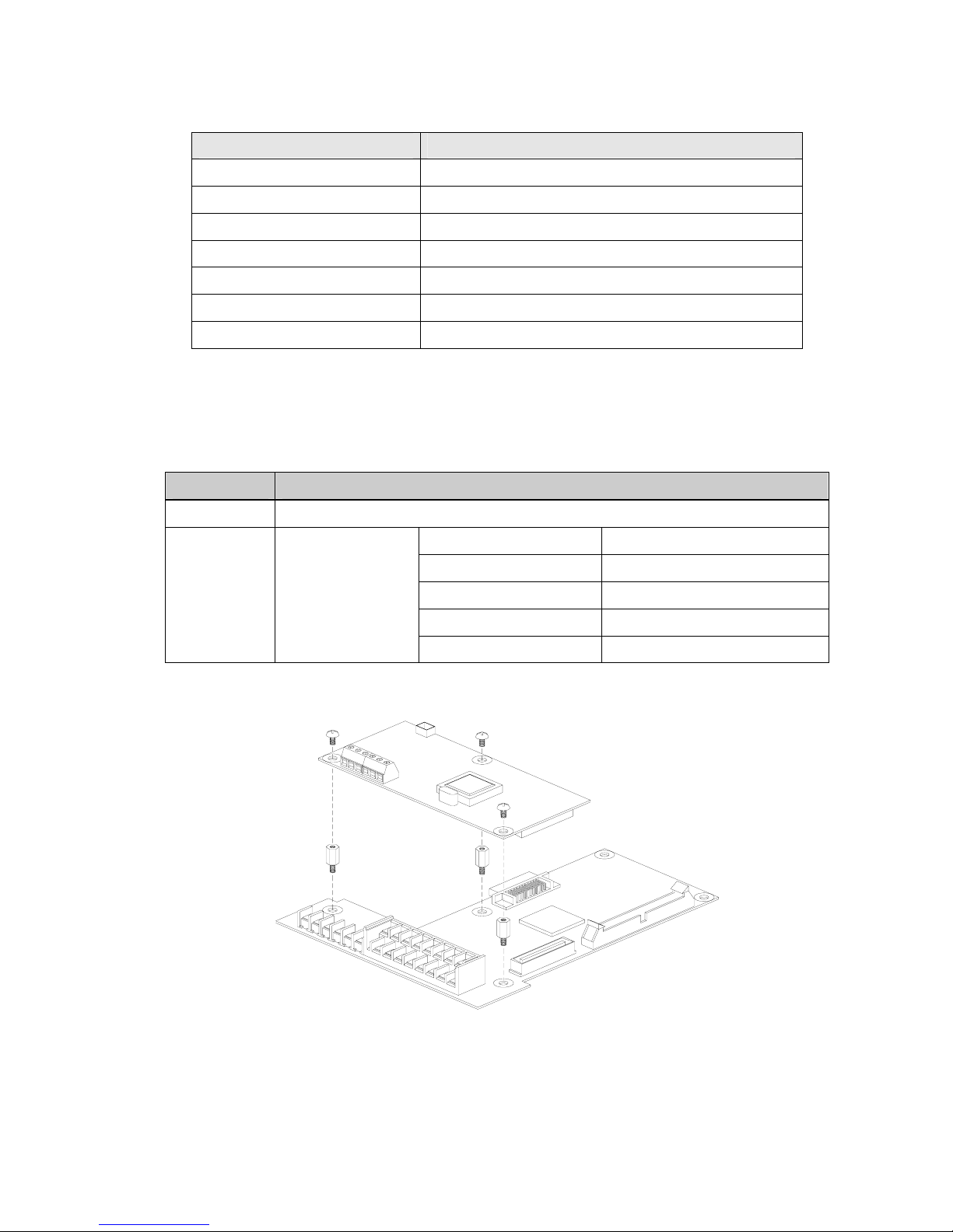
1. Remove the keypad on the inverter and connect the RS485 option board (See the Figure 1).
2. Double check the board is firmly installed to the board and then apply the inverter power.
3. When power ON, CPU LED is blinking per second after all LEDs blink one after another.
4. If “CPU LED” is not blinking, turn off the inverter power swiftly (if not, inverter and the board may get
damaged.) and check for the proper installation of the board. If the problem persists, contact LG
distributor.
5. Check I/O 47 is set to “RS485”.
6. When the above condition is met, set the communication parameters as shown below.
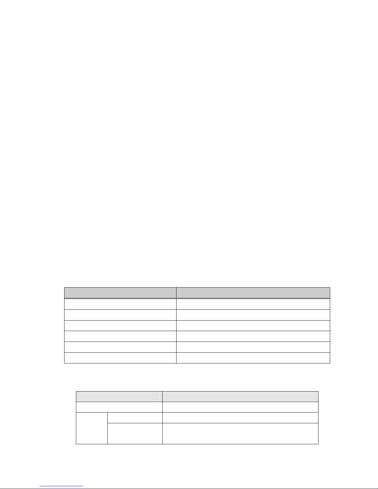
[For SV-iS5]
Parameter code Display Setting Value
< COM-01 > Opt B/D RS485 displayed automatically
< COM-02 > Opt mode Setting command to be controlled by option
< I/O- 46 > Inv. number 1~31
(Verify the assigned number is not duplicated.)
< I/O- 47 > Baud-rate 9600 bps (Factory default)
< I/O- 48 > Lost command (Note 1) User defined
< I/O- 49> Time.Out (Note 1) 0.1 sec (Factory default)
Note1) set for emergency stop of the inverter when inverter and master communication becomes
faulty. Activates when communcation has not been made during setting time. This means remote
controlling of inverter has not executed. Set these for safe use of the inverter.
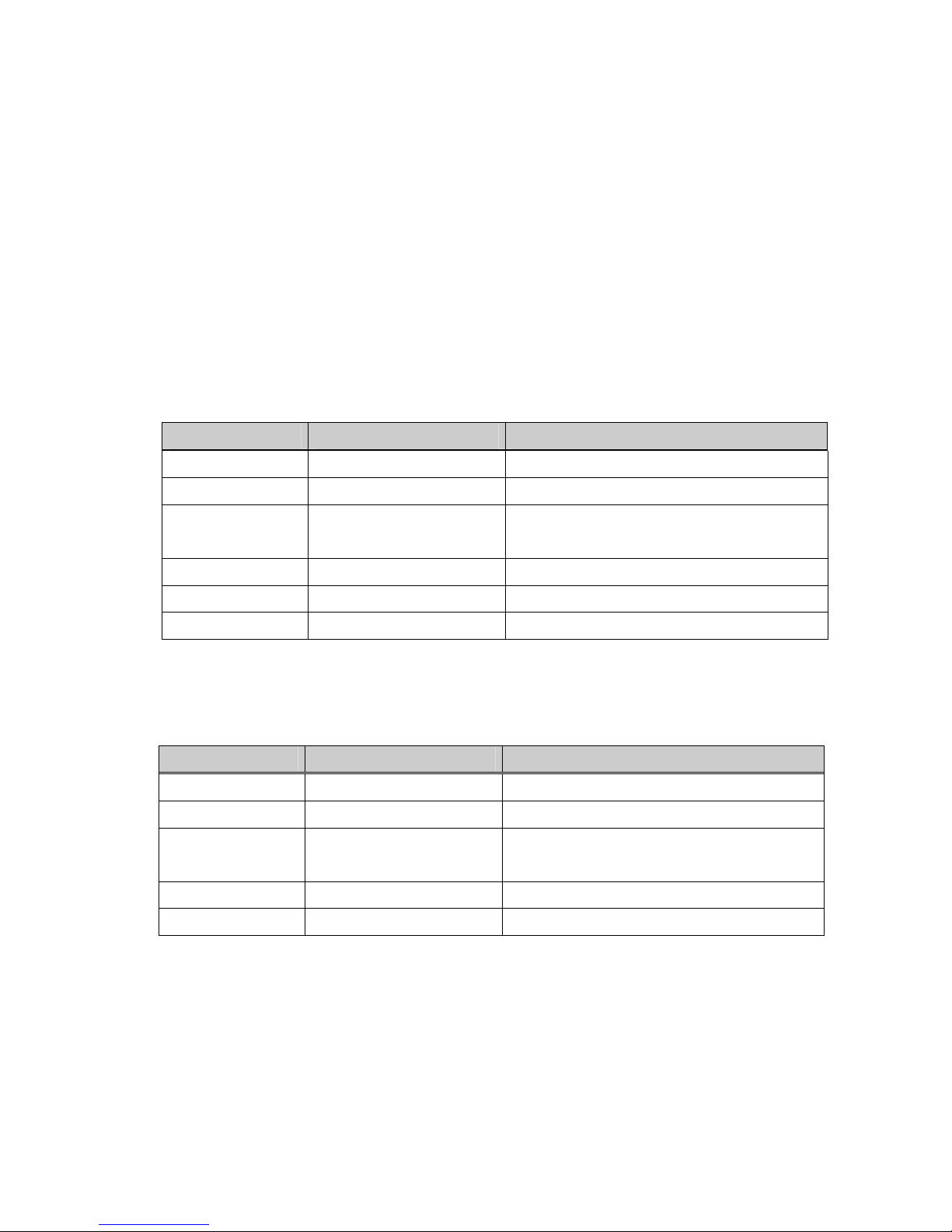
[For SV-iH]
Parameter code Display Setting Value
< FUN-01 > Freq. set “Remote”
< FUN-02 > Run/stop set “Remote“
< I/O- 50 > Inv. number 1~31
(Verify the assigned number is not duplicated.)
< I/O- 51 > Baud-rate 9600 bps (Factory default)
< I/O- 52 > Comm.timeout(Note1) 10.0 (Factory default)
Note1) set for emergency stop of the inverter when inverter and master communication becomes
faulty. Activates when communcation has not been made during setting time. This means remote
controlling of inverter has not executed. Set these for safe use of the inverter.
If Comm. Timeout is set to “0”, inverter maintains its status without stopping at the event of
network communication disconnection.
7. Turn off the inverter power to connect the converter when step 6 is finished.
8. Connect the terminating resistor at the end of network (See the figure 3).
Morek
IT
OÜ,
Rauna
24,
76506
Saue
Harjumaa,
Estonia.
www.morek.eu
Tel.
+372
604
1423
Fax
+372
604
1447
[email protected]