LG GC-P207 User manual

CAUTION
PLEASE READ CAREFULLY THE SAFETY PRECAUTIONS OF THIS BOOK
BEFORE CHECKING OR OPERATING THE REFRIGERATOR.
REFRIGERATOR
SERVICE MANUAL
Ref No :
GC-L207
Ref No :
GC-C207
Ref No :
GC-B207
Ref No :
GC-P207
http://biz.lgservice.com

WARNINGS AND PRECAUTIONS FOR SAFETY ................................................................................................................ 3
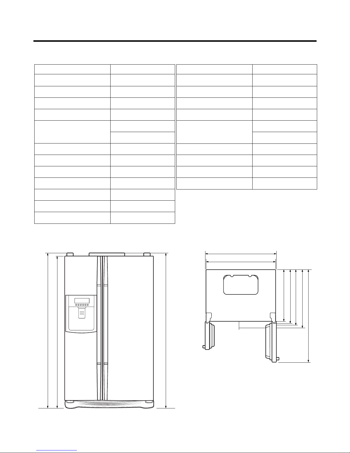
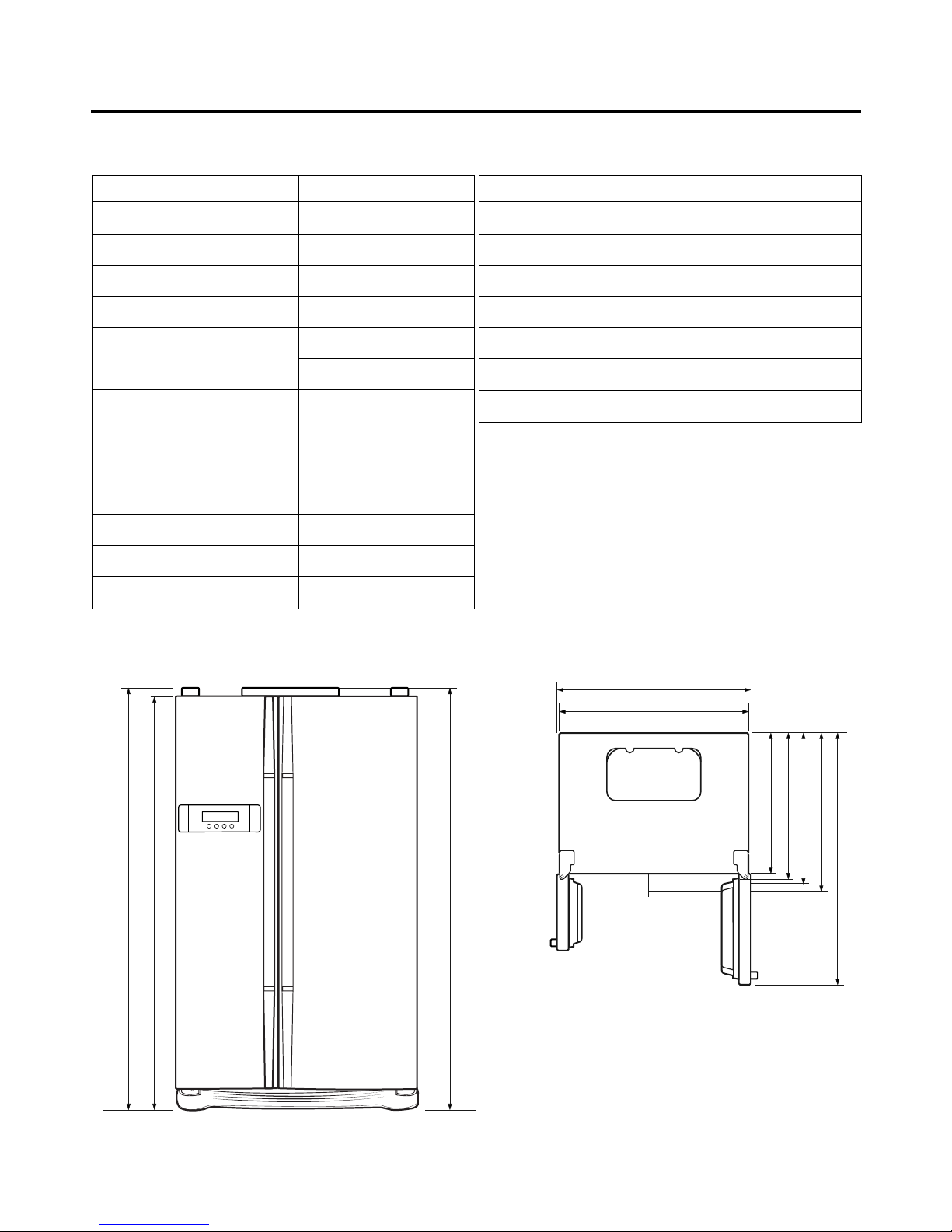
SPECIFICATIONS................................................................................................................................................................... 4
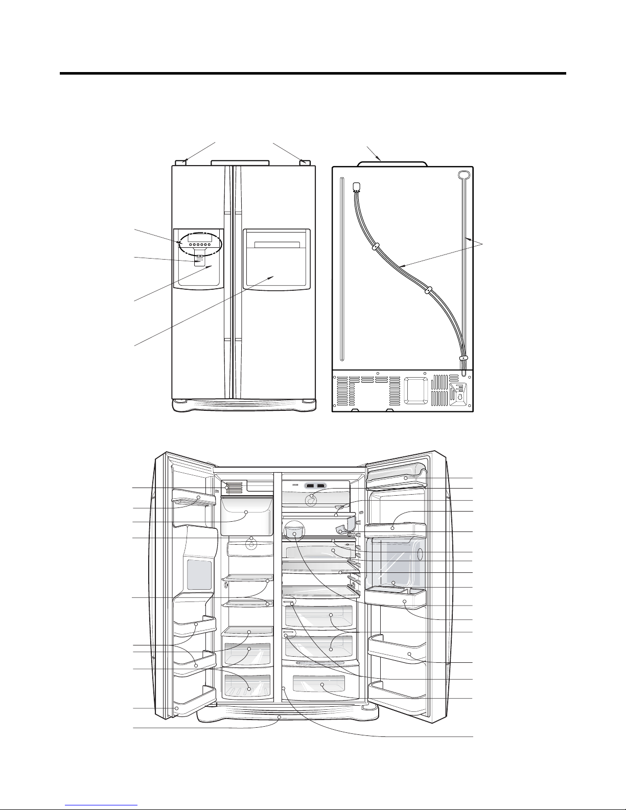
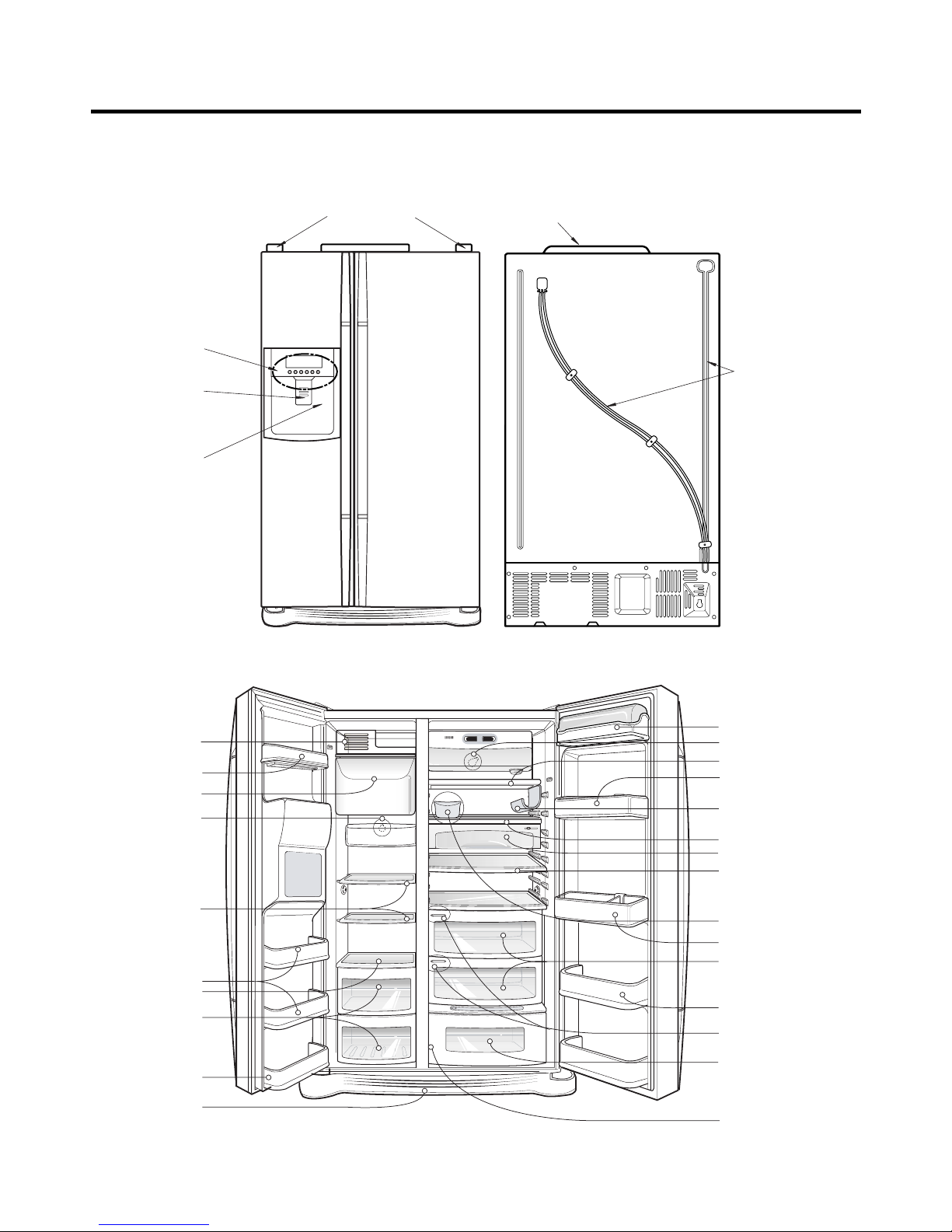
PARTS IDENTIFICATION ....................................................................................................................................................... 8
HOW TO INSTALL THE REFRIGERATOR .......................................................................................................................... 14
HOW TO ADJUST DOOR HEIGHT OF THE REFRIGERATOR ........................................................................................ 14
HOW TO INSTALL WATER PIPE........................................................................................................................................15
HOW TO CONTROL THE AMOUNT OF WATER SUPPLIED TO THE ICEMAKER ......................................................... 19
MICOM FUNCTION .............................................................................................................................................................. 21
EXPLATION FOR MICOM CIRCUIT..................................................................................................................................... 31
EXPLANATION FOR PWB CIRCUIT ................................................................................................................................. 31
COMPENSATION CIRCUIT FOR WEAK-COLD, OVER-COLD AT FREEZING ROOM.................................................... 60
PWB PARTS DRAWING AND LIST ................................................................................................................................... 61
PWB CIRCUIT DIAGRAM .................................................................................................................................................. 76
ICE MAKER AND DISPENSER WORKING PRINCIPLES AND REPAIR ...........................................................................86
WORKING PRINCIPLES.................................................................................................................................................... 86
FUNCTION OF ICE MAKER .............................................................................................................................................. 87
ICE MAKER TROUBLESHOOTING................................................................................................................................... 90
ICE MAKER CIRCUITS...................................................................................................................................................... 91
CIRCUIT................................................................................................................................................................................ 93
TROUBLE DIAGNOSIS........................................................................................................................................................ 95
TROUBLE SHOOTING ...................................................................................................................................................... 95
FAULTS ............................................................................................................................................................................ 105
COOLING CYCLE HEAVY REPAIR ................................................................................................................................. 122
HOW TO DEAL WITH CLAIMS........................................................................................................................................ 126
HOW TO DISASSEMBLE AND ASSEMBLE..................................................................................................................... 131
DOOR............................................................................................................................................................................... 131
HANDLE ........................................................................................................................................................................... 132
SHROUD, GRILLE FAN ................................................................................................................................................... 132
ICEMAKER....................................................................................................................................................................... 132
DISPENSER..................................................................................................................................................................... 133
HOME BAR ...................................................................................................................................................................... 135
EXPLODED VIEW .............................................................................................................................................................. 136
REPLACEMENT PARTS LIST ........................................................................................................................................... 145
CONTENTS
- 2 -

Please observe the following safety precautions in order to
use safely and correctly the refrigerator and to prevent
accident and danger during repair.
1. Be care of an electric shock. Disconnect power cord
from wall outlet and wait for more than three minutes
before replacing PWB parts. Shut off the power
whenever replacing and repairing electric components.
2. When connecting power cord, please wait for more than
five minutes after power cord was disconnected from the
wall outlet.
3. Please check if the power plug is pressed down by the
refrigerator against the wall. If the power plug was
damaged, it may cause fire or electric shock.
4. If the wall outlet is over loaded, it may cause fire. Please
use its own individual electrical outlet for the refrigerator.
5. Please make sure the outlet is properly earthed,
particularly in wet or damp area.
6. Use standard electrical components when replacing
them.
7. Make sure the hook is correctly engaged.
Remove dust and foreign materials from the housing
and connecting parts.
8. Do not fray, damage, machine, heavily bend, pull out,
or twist the power cord.
9. Please check the evidence of moisture intrusion in the
electrical components. Replace the parts or mask it
with insulation tapes if moisture intrusion was
confirmed.
10. Do not touch the icemaker with hands or tools to
confirm the operation of geared motor.
11. Do not let the customers repair, disassemble, and
reconstruct the refrigerator for themselves. It may
cause accident, electric shock, or fire.
12. Do not store flammable materials such as ether,
benzene, alcohol, chemicals, gas, or medicine in the
refrigerator.
13. Do not put flower vase, cup, cosmetics, chemicals,
etc., or container with full of water on the top of the
refrigerator.
14. Do not put glass bottles with full of water into the
freezer. The contents shall freeze and break the glass
bottles.
15. When you scrap the refrigerator, please disconnect the
door gasket first and scrap it where children are not
accessible.
WARNINGS AND PRECAUTIONS FOR SAFETY
- 3 -

SPECIFICATIONS
- 4 -
ITEMS SPECIFICATIONS
DIMENSIONS (mm) 890(W)
X
725(D)
X
1750(H)
NET WEIGHT (kg) 121
COOLING SYSTEM Fan Cooling
TEMPERATURE CONTROL Micom Control
DEFROSTING SYSTEM Full Automatic
Heater Defrost
INSULATION Cyclo-Pentane
COMPRESSOR P.T.C. Starting Type
EVAPORATOR Fin Tube Type
CONDENSER Wire Condenser
REFRIGERANT R600a (82g)
LUBRICATING OIL MO 7 (350 cc)
DRIER MOLECULAR SIEVE XH-9
CAPILLARY TUBE ID 0.85
1750
1720
1750
600
948
890
666
711
725
1133.5
<Front View> <Plane View>
1. Ref No. : GC-P207
ITEMS SPECIFICATIONS
FIRST DEFROST 4 - 5 Hours
DEFROST CYCLE 13 - 15 Hours
DEFROSTING DEVICE Heater, Sheath
ANTI SWEAT HEATER Dispenser Duct Door Heater
Dispenser Heater
Home Bar Heater
ANTI-FREEZING HEATER Damper Heater
FREEZER LAMP 40W (1 EA)
REFRIGERATOR LAMP 40W (1 EA)
DISPENSER LAMP 15W (1 EA)

SPECIFICATIONS
- 5 -
ITEMS SPECIFICATIONS
DIMENSIONS (mm) 890(W)
X
725(D)
X
1750(H)
NET WEIGHT (kg) 120
COOLING SYSTEM Fan Cooling
TEMPERATURE CONTROL Micom Control
DEFROSTING SYSTEM Full Automatic
Heater Defrost
INSULATION Cyclo-Pentane
COMPRESSOR P.T.C. Starting Type
EVAPORATOR Fin Tube Type
CONDENSER Wire Condenser
REFRIGERANT R600a (82g)
LUBRICATING OIL MO 7 (350 cc)
DRIER MOLECULAR SIEVE XH-9
ITEMS SPECIFICATIONS
CAPILLARY TUBE ID 0.85
FIRST DEFROST 4 - 5 Hours
DEFROST CYCLE 13 - 15 Hours
DEFROSTING DEVICE Heater, Sheath
ANTI SWEAT HEATER Dispenser Duct Door Heater
Dispenser Heater
ANTI-FREEZING HEATER Damper Heater
FREEZER LAMP 40W (1 EA)
REFRIGERATOR LAMP 40W (1 EA)
DISPENSER LAMP 15W (1 EA)
1750
1720
1750
600
948
890
666
711
725
1133.5
<Front View> <Plane View>
2. Ref No. : GC-L207

SPECIFICATIONS
- 6 -
ITEMS SPECIFICATIONS
DIMENSIONS (mm) 890(W)
X
725(D)
X
1750(H)
NET WEIGHT (kg) 107
COOLING SYSTEM Fan Cooling
TEMPERATURE CONTROL Micom Control
DEFROSTING SYSTEM Full Automatic
Heater Defrost
INSULATION Cyclo-Pentane
COMPRESSOR P.T.C. Starting Type
EVAPORATOR Fin Tube Type
CONDENSER Wire Condenser
REFRIGERANT R600a (82g)
LUBRICATING OIL MO 7 (350 cc)
DRIER MOLECULAR SIEVE XH-9
CAPILLARY TUBE ID 0.85
1750
1720
1750
600
948
890
666
711
725
1133.5
<Front View> <Plane View>
3. Ref No. : GC-C207
ITEMS SPECIFICATIONS
FIRST DEFROST 4 - 5 Hours
DEFROST CYCLE 13 - 15 Hours
DEFROSTING DEVICE Heater, Sheath
ANTI SWEAT HEATER Home Bar Heater
ANTI-FREEZING HEATER Damper Heater
FREEZER LAMP 40W (1 EA)
REFRIGERATOR LAMP 40W (1 EA)

SPECIFICATIONS
- 7 -
ITEMS SPECIFICATIONS
DIMENSIONS (mm) 890(W)
X
725(D)
X
1750(H)
NET WEIGHT (kg) 106
COOLING SYSTEM Fan Cooling
TEMPERATURE CONTROL Micom Control
DEFROSTING SYSTEM Full Automatic
Heater Defrost
INSULATION Cyclo-Pentane
COMPRESSOR P.T.C. Starting Type
EVAPORATOR Fin Tube Type
CONDENSER Wire Condenser
REFRIGERANT R600a (82g)
LUBRICATING OIL MO 7 (350 cc)
DRIER MOLECULAR SIEVE XH-9
ITEMS SPECIFICATIONS
CAPILLARY TUBE ID 0.85
FIRST DEFROST 4 - 5 Hours
DEFROST CYCLE 13 - 15 Hours
DEFROSTING DEVICE Heater, Sheath
ANTI-FREEZING HEATER Damper Heater
FREEZER LAMP 40W (1 EA)
REFRIGERATOR LAMP 40W (1 EA)
1750
1720
1750
600
948
890
666
711
725
1133.5
<Front View> <Plane View>
4. Ref No. : GC-B207

PARTS IDENTIFICATION
- 8 -
Freezer
compartment
Refrigerator
compartment
Milk product corner
Door rack
Space plus
Lamp
Automatic
ice maker
Shelf
(steel or glass)
Shelf
Door rack
Drawer
Door rack
Lower cover
Lamp
Shelf
Door rack
(1piece or 2piece)
Door rack
(1piece or 2piece)
Door rack
Shelf
Snack drawer (Optional)
Shelf(Folding or Normal)
*Refreshment center
(Optional)
Egg box
Vegetable drawer
(1 or 2)
*Miracle Zone (Optional)
Fresh compartment
(Optional)
*
Conversion switch
(Meats/Vegetables)
(Optional)
* Optional
Humidity switch
*Wine holder
(Plastic or wire)
Cover Hinge
Home Bar
Frame Display
Cover PWB
Water Tube
Dispenser Lamp
Ice & Water
Dispenser Button
1. Ref No. : GC-P207(Internal Filter)

2. Ref No. : GC-P207(External Filter)
PARTS IDENTIFICATION
- 9 -
Freezer
compartment
Refrigerator
compartment
Milk product corner
Door rack
Space plus
Lamp
Automatic
ice maker
Shelf
(steel or glass)
Shelf
Door rack
Drawer
Door rack
Lower cover
Lamp
Shelf
Door rack
(1piece or 2piece)
Door rack
(1piece or 2piece)
Door rack
Shelf
Snack drawer (Optional)
Shelf(Folding or Normal)
*Refreshment center
(Optional)
Egg box
Vegetable drawer
(1 or 2)
*Miracle Zone (Optional)
Fresh compartment
(Optional)
*
Conversion switch
(Meats/Vegetables)
(Optional)
* Optional
Humidity switch
*Wine holder
(Plastic or wire)
Cover Hinge
Home Bar
Frame Display
Cover PWB
Water Tube
Dispenser Lamp
Ice & Water
Dispenser Button

PARTS IDENTIFICATION
- 10 -
Freezer
compartment
Refrigerator
compartment
Milk product corner
Door rack
Space plus
Lamp
Automatic
ice maker
Shelf
(steel or glass)
Shelf
Door rack
Drawer
Door rack
Lower cover
Lamp
Shelf
Door rack
(1piece or 2piece)
Door rack
(1piece or 2piece)
Door rack
Shelf
Snack drawer (Optional)
Shelf(Folding or Normal)
Egg box
Vegetable drawer
(1 or 2)
*Miracle Zone (Optional)
Fresh compartment
(Optional)
*
Conversion switch
(Meats/Vegetables)
(Optional)
* Optional
Humidity switch
*Wine holder
(Plastic or wire)
Cover PWB
Water Tube
Cover Hinge
Frame Display
Dispenser Lamp
Ice & Water
Dispenser Button
3. Ref No. : GC-L207(Internal Filter)

4. Ref No. : GC-L207(External Filter)
PARTS IDENTIFICATION
- 11 -
Freezer
compartment
Refrigerator
compartment
Milk product corner
Door rack
Space plus
Lamp
Automatic
ice maker
Shelf
(steel or glass)
Shelf
Door rack
Drawer
Door rack
Lower cover
Lamp
Shelf
Door rack
(1piece or 2piece)
Door rack
(1piece or 2piece)
Door rack
Shelf
Snack drawer (Optional)
Shelf(Folding or Normal)
Egg box
Vegetable drawer
(1 or 2)
*Miracle Zone (Optional)
Fresh compartment
(Optional)
*
Conversion switch
(Meats/Vegetables)
(Optional)
* Optional
Humidity switch
*Wine holder
(Plastic or wire)
Cover PWB
Water Tube
Cover Hinge
Frame Display
Dispenser Lamp
Ice & Water
Dispenser Button

PARTS IDENTIFICATION
- 12 -
Freezer
compartment
Refrigerator
compartment
Door rack
Cover, Lamp-F
Shelf-F
Shelf-F
Door rack
Drawer
Door rack
Lower cover
compartment
Refrigerator
compartment
Milk product corner
Lamp
Shelf
Door rack
(1piece or 2piece)
Door rack
(1piece or 2piece)
Door rack
Shelf
Snack drawer (Optional)
Shelf(Folding or Normal)
Egg box
Vegetable drawer
(1 or 2)
*Miracle Zone (Optional)
Fresh compartment
(Optional)
*
Conversion switch
(Meats/Vegetables)
(Optional)
* Optional
Humidity switch
*Wine holder
(Plastic or wire)
*Refreshment center
(Optional)
Cover Hinge
Home Bar
Cover PWB
1. Ref No. : GC-C207

PARTS IDENTIFICATION
- 13 -
Freezer
compartment
Refrigerator
compartment
Door rack
Cover, Lamp-F
Shelf-F
Shelf-F
Door rack
Drawer
Door rack
Lower cover
compartment
Refrigerator
compartment
Milk product corner
Lamp
Shelf
Door rack
(1piece or 2piece)
Door rack
(1piece or 2piece)
Door rack
Shelf
Snack drawer (Optional)
Shelf(Folding or Normal)
Egg box
Vegetable drawer
(1 or 2)
*Miracle Zone (Optional)
Fresh compartment
(Optional)
*
Conversion switch
(Meats/Vegetables)
(Optional)
* Optional
Humidity switch
*Wine holder
(Plastic or wire)
*Refreshment center
(Optional)
Cover Hinge Cover PWB
2. Ref No. : GC-B207

1. How to Adjust Door Height of Refrigerator
■Make the refrigerator level first. (If the refrigerator is not installed on the flat floor, the height of freezer and refrigerator
door may not be the same.)
1. If the height of freezer door is lower than that of
refrigerator compartment :
2. If the height of freezer door is higher than that of
refrigerator compartment :
Insert a driver into the groove of adjusting screw
and rotate driver in arrow direction (clockwise) until the
refrigerator becomes horizontal.
Insert a driver into the groove of adjusting screw
and rotate driver in arrow direction (clockwise) until the
refrigerator becomes horizontal.
HOW TO INSTALL REFRIGERATOR
- 14 -
1
1
2
2
Adjusting
Adjusting
Driver
Driver

2. How to Install Water Pipe
■Before Installation
1. The icemaker requires the water pressure of 1.5 -
8.5kgf/cm2. (It is acceptable if city water fills a cup of
180cc with water for 3 seconds)
2. Install booster pump where the city water pressure is
below 1.5kgf/cm2for normal operation of water and ice
dispenser.
3. The total length of water pipe shall be less than 12m. Do
not bend the pipe at right angle. If the length is more
than 12m, there will be troubles on water supply due to
water pressure drop.
4. Please install water pipe where there is no heat around.
2-1. When connecting directly to the water tap.
■Please confirm the following installation parts.
HOW TO INSTALL REFRIGERATOR
- 15 -
Class. Shape and Spec. Nomenclature P/No Remarks
Valve Feed 5221JA3001A Common Use
Connector, (MECH) Pipe 4932JA3003A
Conversion Connector(3/4") 6631JA3004A No Holes
Balance Conector(3/4") 6631JA3004B
Packing(ø24x3t) 3920JA3001B
Connector, (MECH) Pipe 4932JA3003B
Conversion Connector(W25) 6631JA3004C No Holes
Balance Conectoor(W25) 6631JA3004D
Packing(ø23x3t) 3920JA3001A
Connector, (MECH) Pipe 4932JA3003C
Conversion Connector(W28) 6631JA3004E No Holes
Balance Conector(W28) 6631JA3004F
Packing(ø26x3t) 3920JA3001C
Connector, (MECH) Pipe 4932JA3003D
Conversion Connector(1/2") 6631JA3004G No Holes
Balance Conector(1/2") 6631JA3004H
Packing(ø19x3t) 3920JA3001D
Conve-
rtible
Water
Valve
Water
Conn-
ector
Valve Feed Rubber, Packing Connector, Pipe
Tape, TeflonConnector, Pipe

1. Connection of Pipe Connector A and B.
1) Turn off main valve of water pipe.
2) Disconnect water tap from piping by loosening nuts.
3) Connect pipe connector A and B to piping after sealing
the pipe connector with sealing tapes.
4) Connect feed valve to pipe connector A.
5) If there is only one tap water pipe, connect pipe
connector A only and install feed pipe.
2. Water Supply
1) After the installation of feed water, plug the refrigerator
to the earthered wall outlet, press the water dispenser
button for 2 - 3 minutes, and confirm that the water
comes out.
Caution : • Feed pipe should be connected to cold water
line. If it is connected to hot water line, trouble
may occur.
•Please check rubber packing when connecting
feed pipe.
2) Check leakage at connecting part, then arrange water
tube and locate the refrigerator at its regular place if
there is no leaking.
HOW TO INSTALL REFRIGERATOR
- 16 -
Single Lever Type Faucet
(general)
Feed
Valve
General Type
Feed
Valve
Two Hands Type Faucet Single Lever Type Faucet (one
hole, tech type and hand spray)
Feed
Valve
Feed
Valve
Pipe Connector B
Hot Water
Pipe Connector A
Feed
Valve
Cold Water
How to wind
Sealing Tapes.
Water Tube
Water Tube
Nut

3. When customer uses bottled water.
*If customer wants to use bottled water, extra pump should be installed as shown below.
1. The pump system should not be on the floor (it may cause noise and vibration). Securely fasten the inlet and outlet
nuts of pump.
2. If there is any leakage after installation, cut the water tube at right angle and reassemble.
3. When put the water tube end into the bottle, leave a clearance between bottle bottom and water tube end.
4 Check water coming out and any leakage.
Caution : •If feed tube is more than 4m, less water will come out due to pressure drops.
•Use standard feed tube to prevent leaking.
■Outternal Filter
1. Filter Fixation
1) There are two types of filter. One is nut type and the other is connector type.
2) Connect feed tube to the filter outlet and water valve connecting tube.
3) Fix the filter at proper place around the sink where it is easy to replace the filter and to receive the cleaning water.
Please consider the length of tube shall be less than 8m when locating filter.
2. Filter Cleaning
1) Connect feed tube to the inlet of feed valve and filter.
2) Clean the main valve and feed valve with water for at
least one minute until clean water comes out.
HOW TO INSTALL REFRIGERATOR
- 17 -
Water Tube or
Nut
Nut Inlet Outlet
Connector Type Nut Type
Water
Filter
Filter Inlet Feed Valve
Hot Water
Cold Water

■Install Water Filter (Applicable to some models only)
■Before Installing water filter
1. Before installing the filter, take out the top shelf of the
refrigerator after tilting it to the direction () and lifting it
to the direction () and move it to the lower part.
2. Remove the lamp cover by pressing the protrusion
under the cover and pulling the cover to the front.
■Installing water filter
1. Initial installation of water filter
Remove the filter substitute cap by turning it
counterclockwise () by 90 degrees and pulling it down.
Note : Keep it safe to use it later when you do not use the
filter.
Remove the red cap from the filter and attach the
sticker. Insert the upper part of the filter () after
aligning with the guideline marked on the control box,
and fasten it by turning it clockwise by 90 degrees.
Note : Check that the guideline and the fastening
indication line are aligned.
2. Replacement of water filter
While holding the lower part of the filter, turn it
counterclockwise () by 90 degrees and pull it down.
Note : Check that the guideline and the loosening
indication line are aligned.
■After installing water filter
Reassemble the lamp cover and the top shelf of the
refrigerator. To place the top shelf of the refrigerator, raise
the front part of the shelf a bit so that the hook of the shelf
is fit into the groove.
In order to clean the water filter system, drain water for
about 3 min.
Note : Then open the door of the refrigerator and check for
water droppings on the shelf under the filter.
Control box
Aligning with the guide line
and the fastening indication line
Aligning with the guide line
and the loosening indication line
Control box
Separation
of red cap
Adhesion
sticker
Substitute
cap
HOW TO INSTALL REFRIGERATOR
- 18 -

3. How to Control the Amount of Water Supplied to Icemaker.
3-1. Confirm the amount of water supplied to the icemaker.
1. Lift and pull out the space plus in the upper part of the freezer compartment.
2. Pull out the ice bank in the upper part of the freezer compartment.
Caution : •Do not put hands or tools into the chute to confirm
the operation of geared motor.
it may damage refrigerator or hurt hands.)
•Check the operation of motor with its operation
noise.
2. Apply electricity after connecting water pipe.
1) Press test switch under the icemaker for two seconds as shown below.
2) The bell rings(ding~dong) and ice tray rotates and water comes out from the icemaker water tube.
3) The water shall be supplied two or three times into the tray. The amount of water supplied for each time is small.
Put a water container under the ice tray and press test switch.
4) When ice tray rotates, the water in it will spill. Collect the spilt water and throw away into the sink.
5) When ice tray has finished rotation, water comes out from the water tube. Confirm the amounts of water in the ice tray.
(refer to fig. The optimum amount of water is 110cc)
* It is acceptable if the adjusted level of water is a bit smaller than optimum level.
HOW TO INSTALL REFRIGERATOR
- 19 -
21
Test Switch
Confirm the amount
of water
Ice maker
Too much
Too little
Optimum level

3-2. Control the amount of water supplied to the icemaker.
Caution : •Please unplug the power cord from the wall outlet and wait for more than three minutes before disconnecting
PWB cover as 310V is applied in the control panel.
1. Disconnect PWB cover from the upper part of the refrigerator.
2. Adjust the amount of water supplied by using DIP switch.
■Water Supplying Time Control Option
1) The water supplying time is set at five seconds when the refrigerator is delivered.
2) The amount of water supplied depends on the setting time and water pressure (city water pressure).
3) If ice cube is too small, increase the water supplying time. This happens when too small water is supplied into the ice tray.
4) If ice cube sticks together, decrease the water supplying time. This happens when too much water is supplied into the ice tray.
Caution : When adjusting the amount of water supplied, adjust step by step. Otherwise the water may spill over.
3. When adjustment of control switch for the amount of water supplied is complete, check the level of water in the ice tray.
HOW TO INSTALL REFRIGERATOR
- 20 -
(+) Driver
1
ON
Switch ON
Switch OFF 23
Confirm the amount
of water
Optimum level
* The quantity of water
supplied depends on DIP
switch setting conditions
and water pressure as it
is a direct tap water
connection type. (the
water supplied is
generally 80 cc to 120 cc)
* DIP switch is on the main
PWB.
TYPE-3(Dot-LED) TYPE-2(Bar-LED) TYPE-1(88-LED)
No DIP SWITCH SETTING
S1 S2
DIP SWITCH SETTING
S1 S2 S3
1
2
3
4
5
6
7
8
OFF OFF 6.5 SEC
ON OFF 5.5 SEC
OFF ON 7.5 SEC
ON ON 8.5 SEC
OFF OFF OFF 6.5 SEC
ON OFF OFF 5.5 SEC
OFF ON OFF 6 SEC
ON ON OFF 7 SEC
OFF OFF ON 7.5 SEC
ON OFF ON 8 SEC
OFF ON ON 9 SEC
ON ON ON 10 SEC
WATER
SUPPLY TIME
WATER
SUPPLY TIME
REMARKS
This manual suits for next models
3
Table of contents
Other LG Refrigerator manuals