LG M2794D-PM.AWM User manual

Make sure to read the Safety Precautions before
using the product.
Keep the User's Guide(CD) in an accessib e p ace
for furture reference.
See the abe attached on the product and give the
information to your dea er when you ask for service.
OWNER’S MANUAL
MM22779944DD

1
PREPARATION
FRONT PANEL CONTROLS
■
This is a simp ified representation of the front pane . The image shown may be somewhat different from your
set.
INPUT MENU VOL CHENTER
CHANNEL
Buttons
VOLUME
Buttons
MENU
Button
ENTER
Button
INPUT
Button
Power
Button
Headphone
Output

2
PREPARATION
BACK PANEL INFORMATION
■
This is a simplified representation of the ba k panel. The image shown may be somewhat different from your
set.
AC IN
AUDIO IN
(RGB/DVI) OPTICAL
DIGITAL
AUDIO OUT
VIDEO
COMPONENT
IN
AV-IN
VIDEO
S-VIDEO
AUDIO
Y
P
B
P
R
L
R
RS-232C IN
(CONTROL & SERVICE)
SERVICE
ONLY
RGB IN (PC)
DVI-D IN (PC)
HDMI IN
1
2
AC IN
ANTENNA/
CABLE IN
AUDIO
(MONO)
LR
2
910 11
1
87 12
56
3 4
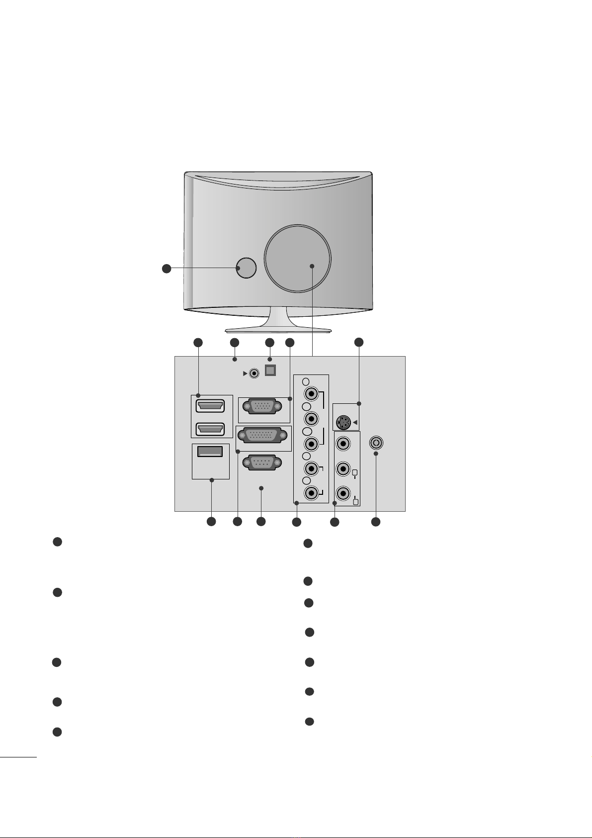
PPoowweerr CCoorrdd SSookkeett
This set operates on AC power. The voltage is indi ated
on the Spe ifi ations page. Never attempt to operate
the set on DC power.
HHDDMMII IInnppuutt
High definition inputs. These two inputs a ept TV
Video, not PC Video. They also a ept TV Video from a
DVI onne tion when using an adapter. The HDMI
inputs support video and audio. When using an adapter
for DVI, they only a ept video.
RRGGBB//DDVVII AAuuddiioo IInnppuutt
This is the audio input for the RGB and DVI-D video
inputs.
OOppttiiaall DDiiggiittaall AAuuddiioo OOuutt
Use this to export audio to an external amplifer.
RRGGBB IINNPPUUTT ((PPCC))
Analog PC input. Also known as VGA.
SS--VViiddeeoo IInnppuutt
Standard definition (480i), but better quality than
standard A/V input.
SSEERRVVIICCEE OONNLLYY PPOORRTT
DDVVII--DD IInnppuutt
Digital PC input.
RRSS--223322CC IINN ((CCOONNTTRROOLL && SSEERRVVIICCEE)) PPOORRTT
Serial port used for external ontrol or servi e.
CCoommppoonneenntt IInnppuutt
High definition analog input.
AAuuddiioo//VViiddeeoo IInnppuutt
Standard definition input.
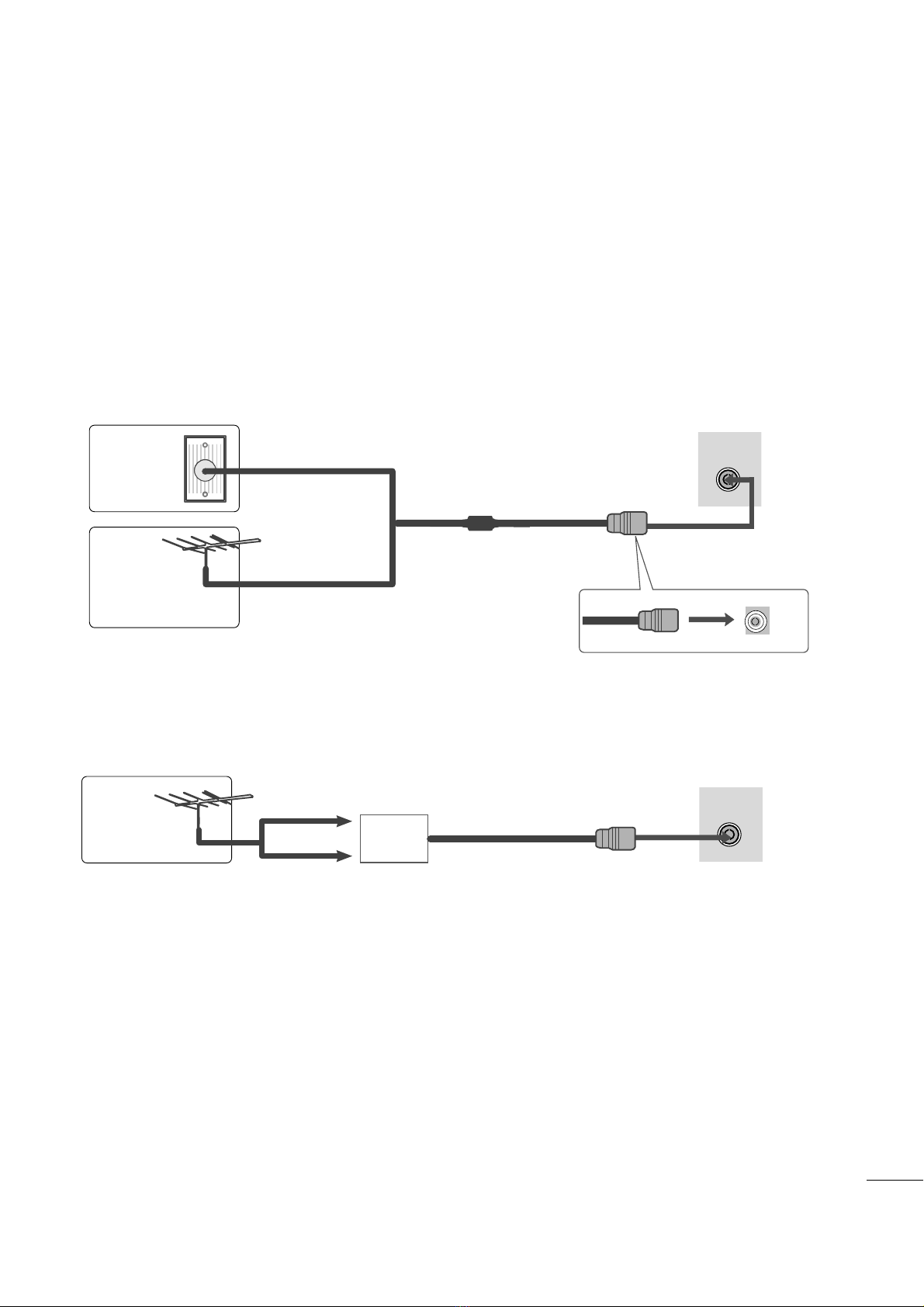
AAnntteennnnaa IInnppuutt
Conne t over-the-air or able signals to this ja k.
1
2
3
4
5
7
6
8
9
10
11
12

3
PREPARATION
STAND INSTALLATION
■
The image shown may be somewhat different from your set.
1
2
3
Carefu y p ace the product screen side down on a
cushioned surface that wi protect product and
screen from damage.
Insert the ssttaanndd bbaasseeinto the product
Attach the monitor to the Stand Base by turning
the screw to the right.
* Turn the screw by using the screw hand e
Screw

4
PREPARATION
DETACHING STAND
12
3
P ace the set screen side down on a cushion or
soft c oth.
Detach the monitor from the Stand Base by
turning the screw to the eft.
Turn the screw by using the screw hand e 4
Pu the stand base.
5
■
The image shown may be somewhat different from your monitor.

5
PREPARATION
DESKTOP PEDESTAL INSTALLATION
For proper venti ation, a ow a c earance of 4 inches on each side and from the wa .
WALL MOUNT: HORIZONTAL INSTALLATION
For proper venti ation, a ow a c earance of 4 inches on each side and from the wa . Fo ow the instructions
inc uded with the wa mount.
4 inches
4 inches
4 inches 4 inches
4 inches
4 inches
4 inches
4 inches
4 inches

6
PREPARATION
POSITIONING YOUR DISPLAY
■
The image shown may be somewhat different from your set.
Adjust the position of the pane in various ways for maximum comfort.
•• TTiitt rraannggee
LOCATION
Position your set so that no bright ight or sun ight fa s direct y onto the screen. Care shou d be taken not to expose
the set to any unnecessary vibration, moisture, dust or heat. A so, ensure that the set is p aced in a position to a ow a
free f ow of air. Do not cover the venti ation openings on the back cover.
If you intend to mount the set to a wa , attach the wa mounting interface (optiona parts) to the back of the set.
When you insta the set using the wa mounting interface (optiona parts), attach it carefu y so it wi not drop.
- Be sure to use screws and a wa mount that meet VESA standards.
- Using screws onger than those recommended might damage the product.
- Using screws that do not meet VESA standards might either damage the product or resu t in it coming away from the
wa . We wi not be he d responsib e for any damage resu ting from fai ure to fo ow these instructions.
< Screw Mounting Interface Dimension >
* 75mm x 75mm ho e spacing
* Wa mount interface(LG) : RW120
-5
°
~ -2
°
7
°
~ 13
°
WWaarrnniinngg::
When adjusting the ang e of the
screen, do not put your finger(s)in
between the head of the monitor
and the stand body. You can hurt
your finger(s).
RW120

7
PREPARATION
SECURING THE SET TO THE WALL TO PREVENT FALLING
WHEN THE SET IS USED ON A STAND
We recommend that you set up the set c ose to a wa so it cannot fa over if pushed backwards.
Additiona y, we recommend that the set be attached to a wa so it cannot be pu ed in a forward direction,
potentia y causing injury or damaging the product.
Caution: P ease make sure that chi dren don’t c imb on or hang from the set.
■Insert the eye-bo ts (or set brackets and bo ts) to tighten the product to the wa as shown in the picture.
*If your product has the bo ts in the eye-bo ts position before inserting the eye-bo ts, oosen the bo ts.
* Insert the eye-bo ts or set brackets/bo ts and tighten them secure y in the upper ho es.
Secure the wa brackets with the bo ts (so d separate y) to the wa . Match the height of the bracket that is
mounted on the wa to the ho es in the product.
Ensure the eye-bo ts or brackets are tightened secure y.
■Use a sturdy rope or cord (so d separate y) to tie the product. It is
safer to tie the rope so it becomes horizonta between the wa and the
product.
■
Image shown may differ from your set.
GWhen moving the set, undo the cords first.
GUse a p atform or cabinet strong enough and arge enough to support the size and weight of the set.
GTo use the set safe y make sure that the height of the bracket on the wa and the one on the set are the same.
NOTE
!

8
PREPARATION
KENSINGTON SECURITY SYSTEM
- The product is equipped with a Kensington Security System connector on the back pane . Connect the
Kensington Security System cab e as shown be ow.
- For detai ed insta ation and use of the Kensington Security System, refer to the user’s guide provided with the
Kensington Security System.
For further information, contact hhttttpp::////wwwwww..kkeennssiinnggttoonn..ccoomm, the internet homepage of the Kensington
company. Kensington se s security systems for expensive e ectronic equipment such as notebook PCs and
LCD projectors.
NOTE
- The Kensington Security System is an optiona accessory avai ab e at most e ectronics stores.
NOTES
a. If the product fee s co d to the touch, there may be a sma “f icker” when it is turned on.
This is norma , there is nothing wrong with product.
b. Some minute dot defects may be visib e on the screen, appearing as tiny red, green, or b ue spots. However,
they have no adverse effect on the monitor's performance.
c. Avoid touching the LCD screen or ho ding your finger(s) against it for ong periods of time.

9
PREPARATION
■For optimum picture qua ity, adjust antenna direction.
■An antenna cab e and converter are not supp ied.
■To prevent equipment damage, never p ug in any power cords unti you have finished connecting a equipment.
Mu ti-fami y Dwe ings/Apartments
(Connect to wa antenna socket)
Sing e-fami y Dwe ings /Houses
(Connect to wa jack for outdoor antenna)
Outdoor
Antenna
(VHF, UHF)
Wa
Antenna
Socket
RF Coaxia Wire (75 ohm)
ANTENNA CONNECTION
Antenna
UHF
VHF
■In poor signa areas, to get better picture qua ity, insta a signa amp ifier to the antenna as shown above.
■If signa needs to be sp it for two TVs, use an antenna signa sp itter for connection.
AC IN
ANTENNA/
CABLE IN
AC IN
ANTENNA/
CABLE IN
Signa
Amp ifier

10
EXTERNAL EQUIPMENT SETUP
Connect the SET-TOP outputs to the CCOOMMPPOONNEENNTT IINN
VVIIDDEEOOsockets (Y PBPR) on the set.
Connect the audio cab e from the SET-TOP to CCOOMMPPOO--
NNEENNTT IINNAAUUDDIIOOsockets of the set.
Press the IINNPPUUTTbutton to se ect CCoommppoonneenntt..
2
3
1
HD RECEIVER SETUP
■To prevent the equipment damage, never p ug in any power cords unti you have finished connecting a equipment.
■
The image shown may be somewhat different from your set.
When connecting with a component cab e
Signa
480i
480p
576p
720p/1080i
1080p
Component
Yes
Yes
No
Yes
Yes
HDMI
No
Yes
Yes
Yes
Yes
VIDEO
COMPONENT
IN
AUDIO
Y
P
B
P
R
L
R
1
2

11
EXTERNAL EQUIPMENT SETUP
When connecting with a HDMI
Connect the HDMI output of the digita set-top box to the
HHDDMMII IINNjack on the set.
1
Connect the digita set-top box to HHDDMMII IINN jack on
the set.
Connect the audio output of the digita set-top box to
the AAUUDDIIOO IINN ((RRGGBB//DDVVII)) jack on the set.
Turn on the digita set-top box. (Refer to the owner’s
manua for the digita set-top box.)
2
3
1
When connecting with a HDMI to DVI cab e
HDMI IN
1
2
1
DVI OUTPUT
AUDIO
R
L
AUDIO IN
(RGB/DVI)
HDMI IN
1
2
12
NOTE
!
GHDMI Input does not support PC mode. If it is connected PC, the screen may not disp ay proper y.

12
EXTERNAL EQUIPMENT SETUP
DVD SETUP
When connecting with a component cab e
Component Input ports
To get better picture qua ity, connect a DVD p ayer to the component input ports as shown be ow.
Component ports on the set
YP
BPR
Video output ports
on DVD p ayer
Y
Y
Y
Y
PB
B-Y
Cb
Pb
PR
R-Y
Cr
Pr
Connect the video output sockets (Y PBPR) of the DVD to
the CCOOMMPPOONNEENNTT IINN VVIIDDEEOO sockets (Y PBPR) of the
set.
Connect the audio cab e from the DVD to CCOOMMPPOO--
NNEENNTT IINN AAUUDDIIOO sockets of the set.
Press the IINNPPUUTTbutton to se ect CCoommppoonneenntt.
Press the PPLLAAYYbutton on the DVD.
The DVD p ayback picture appears on the screen.
2
3
4
1
VIDEO
COMPONENT
IN
AUDIO
Y
P
B
P
R
L
R
1
2

13
EXTERNAL EQUIPMENT SETUP
When connecting HDMI cab e
Connect the HDMI output of the DVD to the
HHDDMMII IINN jack on the set.
1
GHDMI supports video and audio. You do not need to connect a sperate audio cab e.
GIf the DVD p ayer does not support Auto HDMI, you need to set the DVD output reso ution appropriate y.
NOTE
!
HDMI IN
1
2
1
When connecting S-Video
Connect the S-Video output of the DVD to the S-Video in put on the set.
Connect the audio output of the DVD to the AUDIO in put on the set.
1
2
VIDEO AUDIO
(MONO)
S-VIDEO
LR
AV-IN
VIDEO
S-VIDEO
LR
1
2

14
EXTERNAL EQUIPMENT SETUP
VCR SETUP
■To avoid picture noise (interference), eave an adequate distance between the VCR and the set.
■If a user uses 4:3 picture format for a ong time, an afterimage may remain on the sides of the screen for a short
time.
OUTPUT
SWITCH
ANT IN
R
S-VIDEO VIDEO
ANT OUT L
ANTENNA/
CABLE IN
AV 1 AV 2
Wa Jack
Antenna
1
2
When connecting with an antenna
Connect the RF out socket of the VCR to the antenna socket of the set.
Connect the antenna cab e to the RF aeria in socket of the VCR.
Store the VCR channe on a desired channe number using the ‘Manua
channe tuning’ section.
Se ect the Channe number where the VCR channe is stored.
Press the PPLLAAYY button on the VCR.
1
2
3
4
5

15
EXTERNAL EQUIPMENT SETUP
When connecting with a RCA cab e
Connect the audio/video out sockets of the VCR to
AUDIO/VIDEO in sockets of the set.
Press the INPUT button to se ect AV.
Press the PLAY button on the VCR.
The VCR p ayback picture appears on the screen.
2
3
1
When connecting with an S-Video cab e
Connect the S-Video socket of the VCR to the S-
VIDEO socket of the set.
Connect the audio cab e from the S-VIDEO of the VCR
to the AUDIO sockets of the set.
Press the INPUT button to se ect AV.
Press the PLAY button on the VCR.
The VCR p ayback picture appears on the screen.
2
3
4
1
NOTE
!
GIf you have a mono VCR, connect the audio cab e from the VCR to the AUDIO L/MONO jack of the set.
VIDEO AUDIO
(MONO)
S-VIDEO
LR
AV-IN
VIDEO
S-VIDEO
LR
VIDEO AUDIO
(MONO)
S-VIDEO
LR
AV-IN
VIDEO
S-VIDEO LR
1
2
1

16
EXTERNAL EQUIPMENT SETUP
PC SETUP
This product provides P ug and P ay capabi ity, meaning that the PC adjusts automatica y to the set's settings.
When connecting with a D-sub 15 pin cab e
4
Connect the signa cab e from the monitor output socket of
the PERSONAL COMPUTER to the PC input socket of the set.
Connect the audio cab e from the PC to the AAUUDDIIOO IINN
((RRGGBB//DDVVII))sockets of the set.
Press the INPUT button to se ect RRGGBB.
Switch on the PC, and the PC screen appears on the set.
The set can be operated as a PC monitor.
2
3
1
RGB OUTPUT AUDIO
AUDIO IN
(RGB/DVI)
RGB IN (PC)
12
NOTE
!
GUser must use shie ded signa interface cab es (D sub 15 pin cab e, DVI cab e) with ferrite cores to main-
tain standard comp iance for the product.

17
EXTERNAL EQUIPMENT SETUP
When connecting with a DVI cab e
Connect the DVI output of the PC to the DDVVII--DD IINN
jack on the set.
Connect the audio cab e from the PC to the AAUUDDIIOO
IINN ((RRGGBB//DDVVII))sockets of the set.
2
1
NOTE
!
G
If the set is co d, there may be a sma “f icker” when
the set is switched on. This is norma , there is noth-
ing wrong with the set.
G
If possib e, use the 1920x1080@60Hz video mode
to obtain the best image qua ity for your LCD moni-
tor. If used with other reso utions, some sca ed or
processed pictures may appear on the screen. The
set has been preadjusted to the mode
1920x1080@60Hz.
G
Some dot defects may appear on the screen, ike
Red, Green or B ue spots. However, this wi have no
impact or effect on the monitor performance.
G
Do not press the LCD screen with your finger for a
ong time as this may produce some temporary dis-
tortion effects on the screen.
G
Avoid keeping a fixed image on the set’s screen for
pro onged periods of time. The fixed image may
become permanent y imprinted on the screen; use a
screen saver when possib e.
AUDIO
DVI OUTPUT
AUDIO IN
(RGB/DVI)
DVI-D IN (PC)
12

18
EXTERNAL EQUIPMENT SETUP
Tie cab es together with a cab e tie as shown in the
i ustration.
Cab e tie
R
R
BACK COVER FOR WIRE ARRANGEMENT

19
EXTERNAL EQUIPMENT SETUP
RGB/DVI[PC]
HDMI[DTV] supported mode
60
60
50
50
60
60
60
60
50
24
24
30
30
50
60
60
31.47
31.5
31.25
37.5
44.96
45
33.72
33.75
28.125
26.97
23
33.716
33.75
56.25
67.43
67.5
Reso ution
720x480/60p
720x576/50p
1280x720/60p
1280x720/50p
Horizonta
Frequency(kHz) Vertica
Frequency(Hz)
1920x1080/60i
1920x1080/50i
1920x1080/24p
1920x1080/30p
1920x1080/50p
1920x1080/60p
Reso ution
640x480
800x600
720x400
1024 x 768
Horizonta
Frequency(kHz) Vertica
Frequency(Hz)
70
60
75
60
75
60
75
75
60
75
60
60
60
60
31.468
31.469
37.500
37.879
46.875
48.363
60.123
67.500
63.981
79.976
64.674
65.290
75.000
66.587
12 8 0 x 10 24
115 2 x 8 6 4
1680x1050
1920x1080
1600x1200
This manual suits for next models
1
Table of contents
Other LG TV manuals