Life Alert HELP PERS LTE User manual

1
Life Alert HELP PERS LTE
Cellular Wireless Emergency Response System
User's Guide
Cellular Wireless Emergency Response System
This home health care signaling system was designed to support people in
their home environment. In the event of an emergency, help can be
summoned at the press of a Help button and that message will be sent to
Life Alert call center. In the event of fire, the system can be programmed to
automatically call the Life Alert call center
SMS commands may be sent via the 4G/LTE cellular module. Local and
Remote Programming may be performed over SMS and PC connections.
The Unit's LEDs show the system status.
The Unit's rechargeable backup battery provides backup operation. When
AC power is restored, the backup battery is automatically recharged.
What's Included
Before you begin to set up your system, make sure you have all the
necessary components.
Life Alert Help Pers Unit
Input 120VAC 60 Hz / Output 5V DC 1000 mA
Pendant transmitters supplied with necklace or wrist band
Pendant LATR-01

2
SPECIFICATIONS
General Data
Pendant Transmitter Battery Life: 6 years (for typical
use)
Frequency (MHz): 315.
Note: The 315 MHz version only was tested for
compliance with UL standards.
Indicators: 4 LED indicators.
UL Compliant:
Battery Pack: NI-MH 3.7 V, 2.0 Ah
Supply Voltage: 5VDC , 1A (via 120VAC/60Hz
transformer)
Compliance: Complies with FCC part 68 and part 15,
and UL 985 Home Health Care Signaling Equipment.
LEDs:
Indicator
Behavior
Significance
RF LED
Lights
steadily
for 3 sec.
Received RF
signal
No light
No RF signal received.
2
Trouble LED
Lights
steadily
Blinks
Indicates all system
troubles
No light
No trouble.
3
Communication
LED
Light
steadily
Communication with call
center established
Blinks
Contacting Call Center
No light
Communication via
Cellular is offline
4
Power LED
Lights
steadily
AC power is connected.
Blinks
Battery problem
No light
AC power is not
connected.
5
Backlight LEDs
Lights
steadily
When the conditions
below do not exist.
Blinks
No AC Power , on battery
operated
Special Functions:
- Calling for help by using an emergency pendant
transmitter
- Speakerphone (hands-free) when communicating
with Life Alert Call Center
- The system supports up to 15 users (pendant
transmitters and smoke detectors).
- Computer control and data download/upload
- Remote control by SMS commands
- Remote diagnostic and event log using a PC
software or SMS
Physical Properties
Operating Temperature: 32
F to 104
F (0
C to 40
C)
Storage Temperature: -4
F to 140
F (-20
C to 60
C)
Size: 179.5 x 185.5 x 50mm
Weight: 658 gram
Color: White
Note: The product supports Life Alert monitoring center
receivers.
SYSTEM SETUP
To set up your system, follow the steps below.
Select Unit Location
If possible, select a central location in your home for the
Unit. This location should be in the area where you
spend most of your time. The location should also
enable an optimal signal reception for pendants,
smoke , CO detectors and Cellular network .
The Unit can be placed on a table, desk, or counter. It
also can be mounted on a wall.
Make sure that the location you have selected is near
an electrical outlet.
Connect Power to the unit
During normal operation, the unit runs on electrical
power.
1. Insert the plug on the power cord into the "AC"
connector on the unit.
2. Connect the AC/DC adapter into a nearby electrical
outlet. DO NOT USE AN OUTLET CONTROLLED
BY A WALL SWITCH.
5. Turn the ON/OFF switch to ON.
The Unit is now connecting you to
the Monitoring Center
After you complete the steps above press the Help
button, the unit will automatically call Life Alert call
center and the dispatch will be in touch with you .
Transmitters Enrolling
Without PC:
Up to 15 wireless devices / transmitters can be enrolled
locally without a PC. The unit will recognize the device

3
type according to it's ID:
1. Press and hold for 5 seconds both the "CANCEL"
button and ‘’Help ‘’ button. All 4 LEDs should flash
slowly to indicate that the system is in programming
mode.
2. To select the desired transmitter location (zone)
number, click ’’Cancel’’ button repeatedly until the
desired transmitter location number is displayed (see
Table below).. Each press advances to the next
location (zone) number (1 - 15).
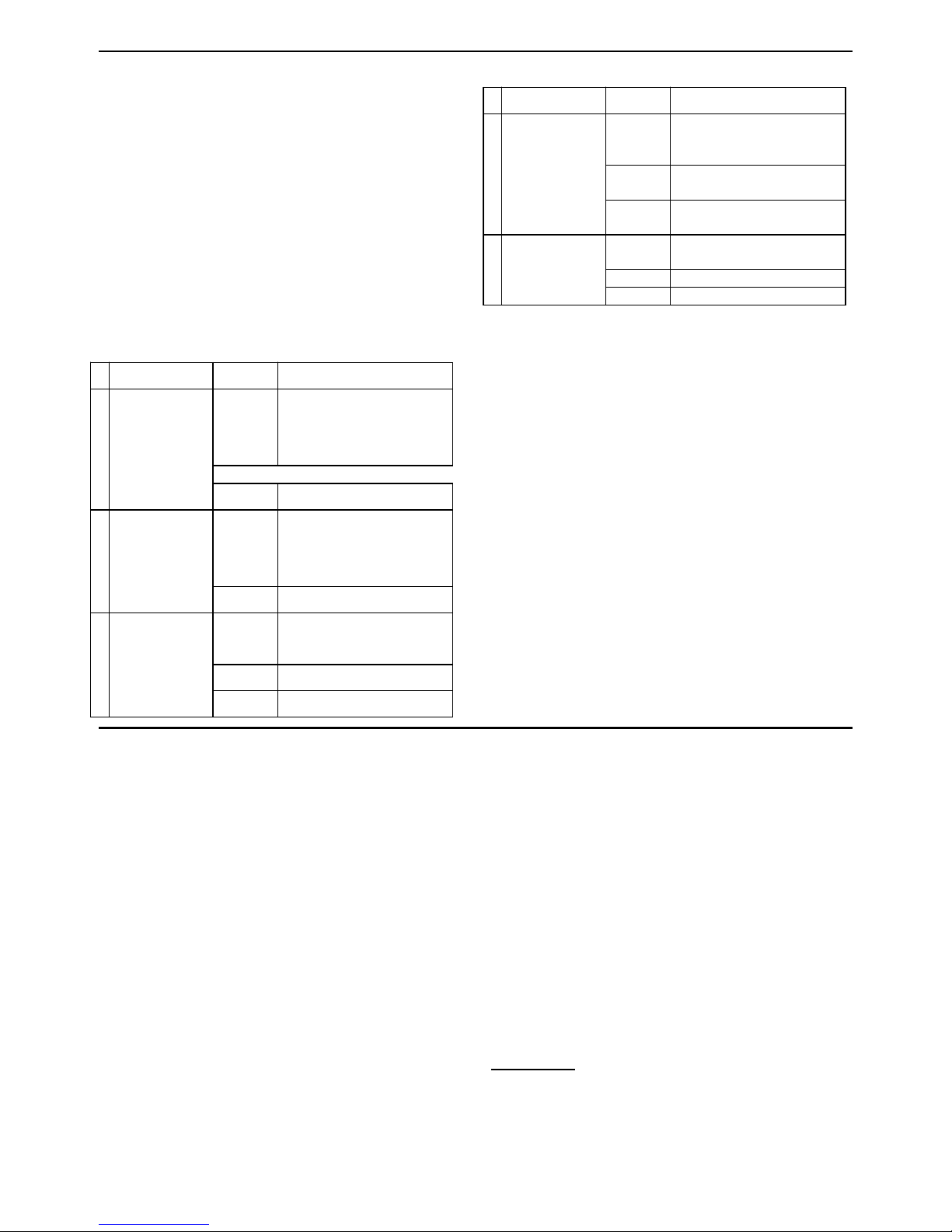
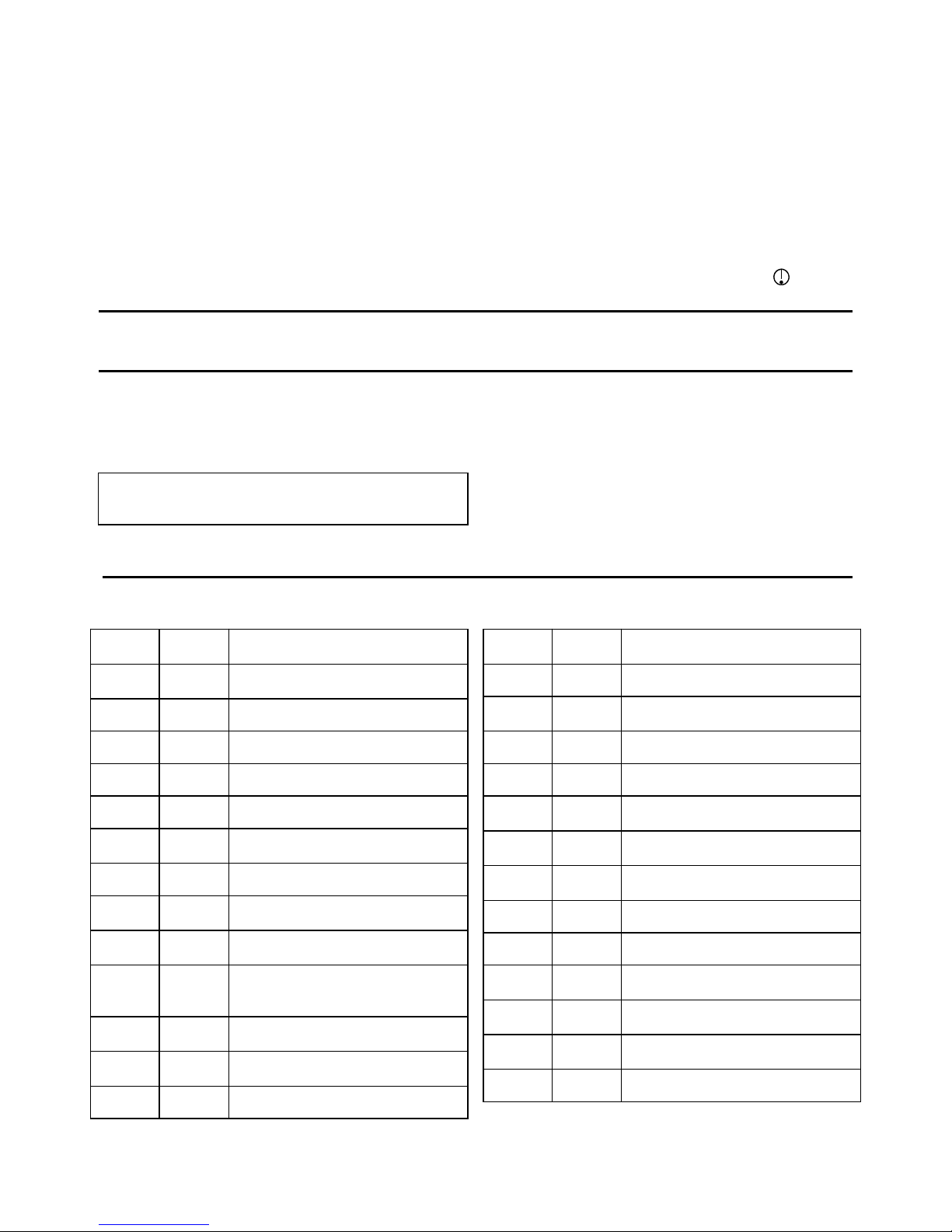
The LEDs lights combination indicates the Location /
zone number, as shown in the following Table:
Flashing light = Free location into which a
transmitter can be enrolled.
Steady light = Occupied location with an enrolled
transmitter.
Table 1 - Zone Number Indication
ZONE
No.
LED
1
ON
–
–
–
2
–
ON
–
–
3
ON
ON
–
–
4
–
–
ON
–
5
ON
–
ON
–
6
–
ON
ON
–
7
ON
ON
ON
–
8
–
–
–
ON
9
ON
–
–
ON
10
–
ON
–
ON
11
ON
ON
–
ON
12
–
–
ON
ON
13
ON
–
ON
ON
14
–
ON
ON
ON
15
ON
ON
ON
ON
16 (Global Zones
clear)
–
–
–
–
3. When the LEDs of the desired location flash, activate
the desired transmitter. Success beeps should be
heard and the proper LEDs combination (see Table
1) should stop flashing and light constantly.
4. To verify that the specific transmitter was properly
enrolled, reactivate the transmitter once again and
verify that all 4 LEDs flash once (in a sequential
manner) and then the LEDs combination
corresponding to the transmitter location return to
light constantly as before.
5. Perform steps 3 - 5 for all other desired transmitters.
6. Exit from programming mode by pressing and
holding for 5 seconds both the "CANCEL" button and
‘’Help’’ button (automatic exit by time out will occur if
no action is performed during 5 minutes).
Deleting Wireless Transmitters
from the System Memory
Using PC:
By using a remote or local PC programmer, it is
possible to delete enrolled wireless transmitters.
Without PC:
Locally (without PC), wireless transmitters can be
deleted from the unit memory, as follows:
1. Press and hold both the "CANCEL" button and
‘’Help’’ button for 5 seconds. All 4 LEDs should flash
slowly to indicate that the system is in programming
mode.
2. To select the desired transmitter to be deleted, click
‘’Cancel’’ button repeatedly until the desired
transmitter location number is displayed (see Table
1). Each press advances to the next location (zone)
number (1 - 15).
3. To delete a selected transmitter, press and hold the
"CANCEL" button for 2 seconds approximately until
the proper LEDs combination will be switched off. As
a result, the LEDs combination of the respective
deleted location (see Table 1) will flash indicating the
location is now free.
Wireless Devices Test
1. Press and hold both the "CANCEL" button and the
‘’Help’’ button for 5 second. All 4 LEDs should flash
to indicate that the system is in programming
mode/Test mode.
2. Activate the transmitter you wish to test and listen to
the system response.
3. Press on ‘’Help’’ button for 2 seconds – the unit will
show the cellular RSSI level .
The unit will play current RSSI level ; Strong ,
Good or Poor . The led indication will show the
RSSI level accordingly:
a. Strong – 4 leds light
b. Good - 3 leds light
c. Poor - 2 leds light
d. Sim card or network problem – 1 led lights
4. Exit the test by pressing and holding both the
"CANCEL" button and ‘’Help’’ button for 5 seconds
(automatic exit by timeout will occur if no action is
performed during 5 minutes).
Using your HELP PERS
Your unit is the communication center of your system.
When your pendant transmitter or smoke detector
signals to the unit , then it contacts Life Alert Monitoring
Center to report the emergency event.
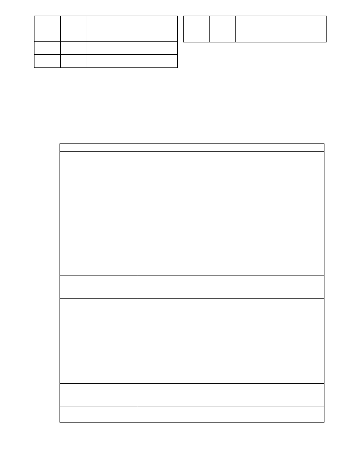
The unit includes the following buttons.
HELP – When pressed, an emergency alarm is
reported to the Life Alert Center or to private phones.
CANCEL – Cancel emergency call
Using your Pendant Transmitter
The pendant transmitter can be used to initiate an

4
emergency call .
Pendant Activation - Your pendant transmitter lets
you signal to the unit from anywhere in your home
when you need emergency assistance. You should
wear your pendant transmitter whenever you are at
home even in the shower or bath. Your pendant
transmitter is waterproof.
Your pendant transmitter can be activated by simply
pushing its button. Once pushed, a signal is sent from
the pendant transmitter to the unit and the red LED
on the pendant transmitter illuminates. The unit then
calls Life Alert call center.
Neckband - You can wear the pendant transmitter
using the neckband, it exists in the transmitter kit.
Optional Wristband - Your pendant transmitter can
also be used with an optional wristband.
Calling for Help
If you need emergency assistance, press the button on
your pendant transmitter or press the HELP button on
the main unit.
The unit calls Life Alert Monitoring Center and sends an
emergency alarm. When your Monitoring Center
representative answers, you can hear them talking to
you through the unit speakerphone.
Trouble
Trouble conditions are indicated by LED and are
immediately reported to the Life Alert Center.
Pendant test
Regular testing of your pendant(s) . Recommended
testing once a week
MAINTAINING YOUR SYSTEM
The transmitter may get dirty if touched with greasy
fingers. Clean it only with a soft cloth or sponge
moistened lightly with a mixture of water and mild
detergent, and wipe it dry immediately.
The use of abrasives of any kind is strictly
forbidden. Also never use solvents such as
kerosene, acetone or thinner.
When a Pendant's Battery is Low
When a pendant transmitter's battery is low, the
transmitter informs Life Alert Monitoring Center. In this
case the red led illuminates repeatedly.
When a Smoke Detector's Battery is
Low
When a smoke detector's battery voltage is low, the
panel will inform Life Alert Monitoring Center.
APPENDIX A : SIA EVENT CODES
EVENT
CODE
ZONE
#
EVENT
DESCRIPTION
QA
55
EMERGENCY ALARM
(CONSOLE)
RP
55
PERIODIC TEST
AT
55
A/C LOSS
AR
55
A/C LOSS RESTORE
YT
55
LOW BATTERY TO CONSOLE
YR
55
RESTORAL TO LOW BATTERY
TO CONSOLE
YM
55
SYSTEM BATTERY MISSING
YS
55
SYSTEM SHUTDOWN (POWER
OFF THE UNIT)
RR
55
POWER UP (POWER ON THE
UNIT)
AB
55
ALARM CANCELLED (RESET
BUTTON ON CONSOLE
PUSHED)
XT
Variable
LOW BATTERY TO
TRANSMITTER
XR
Variable
RESTORAL TO LOW BATTERY
TO TRANSMITTER
XS
Variable
TRANSMITTER LOST
EVENT
CODE
ZONE
#
EVENT
DESCRIPTION
SUPERVISION
XJ
Variable
RESTORAL TO TRANSMITTER
LOST SUPERVISION
TA
Variable
TAMPER ALARM
TR
Variable
TAMPER RESTORE
MA
Variable
MEDICAL ALARM (NECK
PENDANT AND WATCH)
MT
Variable
MEDICAL TRANSMITTER LOW
BATTERY
MR
Variable
RESTORAL TO MEDICAL
TRANSMITTER LOW BATTERY
GA
Variable
GAS ALARM
GT
Variable
GAS SENSOR LOW BATTERY
GR
Variable
RESTORAL TO GAS SENSOR
LOW BATTERY
GS
Variable
GAS SENSOR LOST
SUPERVISION
GJ
Variable
RESTORAL TO GAS SENSOR
LOST SUPERVISION
FA
Variable
FIRE ALARM

5
EVENT
CODE
ZONE
#
EVENT
DESCRIPTION
FT
Variable
FIRE SENSOR LOW BATTERY
FR
Variable
RESTORAL TO FIRE SENSOR
LOW BATTERY
FS
Variable
FIRE SENSOR LOST
SUPERVISION
EVENT
CODE
ZONE
#
EVENT
DESCRIPTION
FJ
Variable
RESTORAL TO FIRE SENSOR
LOST SUPERVISION
Remote SMS commands:
The commands structure:
GET – get the data from the unit
SET – set the data to the unit
PW – Password ( default 9999 )
Commands
1. SET APN acount
SETPW#APN#"XXXXXX"#
example: SET9999#APN#"mpers.lifealert.com"#
data return: +APN=XXXXXX
2.SET APN Password
SETPW#USERPW#XXXXXX#
data return: +USERPW=XXXXXX#
3. SET Fibro server 1
address and port
SETPW#IP1#"XXX.XXX.XXX.XXX",XXX#
example: SET9999#IP1#"12.167.62.11",3061#
data return: +IP1="XXX.XXX.XXX.XXX",XXX#
4.SET Fibro server 2
address and port
SETPW#IP2#"XXX.XXX.XXX.XXX",XXX#
data return: +IP2="XXX.XXX.XXX.XXX",XXX#
5. SET the first phone
number
SETPW#PHONE1#XXXXXX#
data return: +PHONE1=XXXXXX#
6.SET the second phone
number
SETPW#PHONE2#XXXXXX#
data return: +PHONE2=XXXXXX#
7. SET Fibro local port
SETPW#LOCALPORT#XXXXXX#
data return: +LOCALPORT=XXXXXX#
8. Read equipment IMEI
GETPW#CGSN#
data return: +IMEI=XXXXXX#
9. Read CSQ ( Signal
quality )
GETPW#CCSQ#
data return: +CCSQ=-XXX#
Poor [2…7 ] ; Good [ 8…14 ] ; Strong [15… 31 and greater ]
-109 …-99dbm; -97 ….- 83dBm; -81 …. – 65dBm
10. Modify SMS
operation password
SETPW#SMSPW#XXXX#
data return +SMSPW=XXXX#
11. Read FW version
GETPW#VERSION#
data return: +VERSION=XXXX#

6
12. Read the latest 8 logs
for the device
GETPW#LOG#
data return: +LOG=XXXX#
13. Modify Fibro data
package account
SETPW#FIBRO#XXXX#
data return: +FIBRO=XXXX#
14. Enrolling Wl devices
SETPW#ZONEX#RFID CODE#
data return: +ZONEX=RFID CODE#
15. Delete Wl devices
SETPW#ZONEX#000000#
data return: +ZONEX=Deleted#
16. SET Mute
SETPW#SOUND#1 On or SETPW#SOUND#0 Off
17. SET Remote Call On
SETPW#RCALL#1 On or SETPW#RCALL#0 Off
18. Full Duplex
SETPW#FULLDUPLEX#1 On or SETPW#FULLDUPLEX#0 Off
19. Remote
Communication test
GETPW#TEST# The unit sends even NTX55 to the receiver
20. AC power failure
report
SETPW#ACREPORT#30#
21. Remote Call allowed
SETPW#RCALL#1
22. Remote TEST
SETPW#TEST# the unit sends code NTX55 to the receiver
23. Periodic test
SETPW#PTEST#1#
24. Periodic test start
SETPW#PTESTSTART#1255#
25. Pendant Supervision
SETPW#PSUPERVISION#7#
26. Event Report delay
SETPW#ERDELAY#15#
COMPLIANCE
FCC STATEMENT
1. This device complies with Part 15 of the FCC Rules. Operation is subject to the following two
conditions:
(1) This device may not cause harmful interference.
(2) This device must accept any interference received, including interference that may cause undesired
operation.
2. Changes or modifications not expressly approved by the party responsible for compliance could void the
user's authority to operate the equipment.
NOTE: This equipment has been tested and found to comply with the limits for a Class B digital device,

7
pursuant to Part 15 of the FCC Rules. These limits are designed to provide reasonable protection against
harmful interference in a residential installation.
This equipment generates uses and can radiate radio frequency energy and, if not installed and
used in accordance with the instructions, may cause harmful interference to radio communications.
However, there is no guarantee that interference will not occur in a particular installation. If this equipment
does cause harmful interference to radio or television reception, which can be determined by turning the
equipment off and on, the user is encouraged to try to correct the interference by one or more of the
following measures:
Reorient or relocate the receiving antenna.
Increase the separation between the equipment and receiver.
Connect the equipment into an outlet on a circuit different from that to which the receiver is connected.
Consult the dealer or an experienced radio/TV technician for help.
FCC Radiation Exposure Statement
This equipment complies with FCC radiation exposure limits set forth for an uncontrolled environment.
This equipment should be installed and operated with minimum distance 20cm between the radiator &
your body

Supplier’s Declaration of Conformity
Responsible party details
Company name:
Life Alert Emergency Response, Inc.
Address:
16027 Ventura Blvd. Suite 400 Encino California United States 91436
Contact Person:
Yasha Sigal
Email:
Phone No.:
+18182075116
Fax No.:
Product details
Product:
Life Alert HELP PERS LTE
Brand name:
Life Alert
Model name:
2ABZ7-919
Manufacturer:
Life Alert Emergency Response, Inc
Address:
16027 Ventura Blvd. Suite 400 Encino California United States 91436
We hereby declare that the equipment bearing the trade name and model number specified above was tested confirming to
the applicable FCC Rules under the most accurate measurement standards possible, and that all the necessary steps have
been taken and are in force to assure that production units of the same equipment will continue to comply with the
Commission’s requirements.
Applied Standards
Report No.:
United States CFR 47 Part 15 Subpart B - Electromagnetic Emissions (Unintentional Radiators)
BL-SZ1810049-401
The product complies with Part 15 of the FCC Rules. Operation is subject to the following two conditions: (1) this device may
not cause harmful interference, and (2) this device must accept any interference received, including interference that may
cause undesired operation.
Signature:
Print name: Yasha Sigal
Date of issue: 3 March 2018
This manual suits for next models
1
Table of contents
Other Life Alert Personal Care Product manuals