LIFE home integration ACER Parts list manual

ACER
VERSIONE 10/2007
AUTOMAZIONE PER CANCELLO SCORREVOLE
ISTRUZIONI E AVVERTENZE PER L`INSTALLAZIONE,E L`USO E LA MANUTENZIONE
ELECTROMECHANICAL OPERATOR FOR SLIDING GATES
INSTRUCTIONS FOR INSTALLATION, USE AND MAINTENANCE
MOTOREDUCTEUR ELECTROMECANIQUE POUR PORTAILS COULISSANTS
INSTRUCTIONS POUR L’INSTALLATION, L’UTILISATION ET L’ENTRETIEN
MOTORREDUCTOR ELECTROMECÁNICO PARA CANCELAS CORREDERAS
INSTRUCCIONES PARA LA INSTALACIÓN, EL USO Y EL MANTENIMIENTO
MOTORREDUCTOR ELECTROMECÂNICO PARA PORTÕES DE CORRER
INSTRUÇÕES PARA A INSTALAÇÃO, USO E MANUTENÇÃO
ELEKTROMECHANISCHER SCHIEBETORANTRIEB
ANLEITUNGEN UND HINWEISE FÜR INSTALLATION, GEBRAUCH UND WARTUNG
MOTOREDUKTOR ELEKTROMECHANICZNY DO BRAM PRZESUWANYCH
INSTRUKCJA MONTAŻU, UŻYTKOWANIA I KONSERWACJI
ЭЛЕКТРОМЕХАНИЧЕСКИЙ РЕДУКТОРНЫЙ МОТОР ДЛЯ РАЗДВИЖНЫХ ВОРОТ
ИНСТРУКЦИЯ ПО МОНТАЖУ, ИСПОЛЬЗОВАНИЮ И ТЕХНИЧЕСКОМУ ОБСЛУЖИВАНИЮ
ELEKTROMECHANICKÝ POHON PRE POSUVNÉ BRÁNY
NÁVOD NA INŠTALÁCIU, POUŽITIE A ÚDRŽBU
ELEKTROMECHANICKÝ POHON PRO POSUVNÉ BRÁNY
NÁVOD NA INSTALACI, UŽÍVÁNÍ A ÚDRŽBU
ELEKTROMECHANIKUS MOTOR TOLÓKAPUKHOZ
UTASÍTÁSUK ÉS FIGYELMEZTETÉSEK TELEPÍTÉSHEZ, HASZNÁLATHOZ ÉS KARBANTARTÁSHOZ

STANDARD INSTALLATION
Fig.1: componenti e dispositivi di un’automazione tipo.
Fig.1: components and devices of a typical automation.
Fig.1: composants et dispositifs d’un automatisme type.
Fig.1: componentes y dispositivos de un automatismo tipo.
Fig.1: componentes e dispositivos de uma automação tipo.
Abb.1: Bestandteile und Vorrichtungen eines Musteranstriebs, siehe Abbildung.
Obr.1: części i urządzenia typowego siłownika.
Рис.1: детали и устройства для оборудования типа см. рис.
Obr. 1: Súčiastky a zariadenia typickej inštalácie, pozri obrázok.
Obr. 1: Součástky a zařízení typické instalace, viz obrázek
Tab.1: általános automatikához tartozó robbantott rajz, lásd ábra.
Tab. 2: descrizione contenuto scatola attuatore ACER.
Fig.2: description of the contents of the ACER pack.
Fig.2: description contenu boîtier ACER.
Fig.2: descripción del contenido de la caja ACER.
Fig.2: descrição do conteúdo da caixa ACER.
Abb.2: Beschreibung des Verpackungsinhalts ACER, siehe Abbildung.
Obr.2: opis zawartości opakowania ACER.
Рис.2: Описание содержимого коробки ACER.
Obr. 2: Popis obsahu škatule ACER, pozri obrázok.
Obr. 2: Popis obsahu balení ACER, viz obrázek
Tab. 2: ACER szetthez tartozó doboz tartalma, lásd ábra.
AC001
RE
C
A
in
o
izu
r
t
si
idela
u
naM
RECA
i
noizu
rts
ii
d
e
l
a
u
naM
GN
I
N
E
P
OR
O
ODC
IT
A
M
O
TU
A
RECA
1 A

1
20
29
29
29
24
25
26
18 19
21
22
23
33-34 35
28
39-40-41-42-43
30-31-32
27
15-16-17
14 9-10-11-12-13
1-2-3-4-5 6-7-8
36-37
38
DESCRIZIONE PARTICOLARI ACER
DESCRIPTION OF ACER PARTS
DESCRIPTIONS PARTICULIERES ACER
DESCRIPCIONES DE LOS DETALLES ACER
DESCRIÇÃO DETALHADA ACER
BESONDERE BESCHREIBUNGEN ACER
OPIS SZCZEGÓŁOWY ACER
ОПИСАНИЕ ОСОБЕННОСТЕЙ ACER
PODROBNÝ POPIS ACER
PODROBNÝ POPIS ACER
ÁLTALÁNOS TELEPÍTÉSI RAJZ
2 A

SIAÇNARF
1
CARACTERISTIQUES TECHNIQUES
LIFE home integration se réserve le droit de varier à tout moment et sans préavis les caractéristiques techniques, en conservant leur emploi et leur fonctionnalité.
ACER: Motoréducteur électromécanique irréversible pour portails coulissants avec encodeur optique / magnétique et centrale électronique incorporée.
Version: CENTRALE - 230 Vca 50 Hz CENTRALE - 24 V d.c.
AC4 / AC4R AC6 / AC6R AC8 AC4 24 P AC6 24 X AC8 24 X
Centrale incorporée RG1A / RG1R RG1A / RG1R RG1A RG1 24 P RG1A 24 X RG1A 24 X
Alimentation secteur V 230 Vac 50 Hz
Alimentation moteur V 230 V a.c. 24 V d.c.
Puissance moteur W 250 280 300 40 80 90
Absorption du secteur 230 V / Absorption max. moteur à la reprise 24 V A 1,1 1,2 1,4 5 6 12
Condensateur µF 14 14 16 NO
Poussée N 500 700 900 300 500 700
Graissage Type graisse huile graisse huile
Thermoprotection °C 140 NO
Fin de course 2 électromécaniques ou magnétique dans la version M
Encodeur optique magnétique optique
Vitesse m/min 10 11
Modulo ruota dentata esterna 4
Module roue dentée externe 18 16 16 16
Cycle de travail % 35 80
Temps de travail nominal min 10 20
Temps recharge batterie (en option)* BATTERIE NON PREVUE 48
Cycles ouverture batterie chargée* BATTERIE NON PREVUE 20 15 10
Température de fonctionnement °C de -20 à +70
Niveau de protection IP 54
Classe d’isolation moteur FD
Montage Horizontal avec la plaque d’ancrage spécifique
Dimensions / poids 170 (plaque) x 342 x 288 (h) mm / 10 kg
Utilisation en atmosphère acide, saline ou potentiellement explosive non
Poids max portail kg 400 600 800 400 600 800
* pour batteries de 2 Ah (en option et installées dans la centrale de commande).
1.0 INSTALLATION
1.1 Déblocage du motoréducteur
Attention:
• L’installateur doit fixer d’une manière permanente l’étiquette concernant le déblocage manuel à côté de la clé pour le déblocage manuel.
• L’activation du déblocage manuel pourrait provoquer un mouvement incontrôlé du portail à cause d’endommagements mécaniques ou de condi-
tions de déséquilibrage mécanique.
• Avant d’effectuer la manœuvre couper l’alimentation électrique à l’automatisme.
• Ne pas forcer sur la clé afin d’éviter de la rompre.
a) Faire glisser le petit couvercle de protection de la serrure (1). Voir fig. (1.1).
b) Enfiler la clé (2) dans la serrure et la tourner vers la droite de 90°. Voir fig. (1.2).
c) Tirer la clé légèrement vers l’extérieur pour faire sortir (16) le petit battant, puis le tirer vers l’extérieur jusqu’à son arrêt. Voir fig. (1.3).
d) Maintenant le motoréducteur est libre et peut être déplacé à la main. Un micro-interrupteur monté sur le dispositif de blocage empêche le moteur
de fonctionner en cas du retour du courant.
e) Opérer dans le sens contraire pour raccrocher la transmission et déplacer le portail à la main jusqu’à sentir son accrochage.
Fig. (1)
AC017
3
2
1
Fig.1.2
Fig.1.1 Fig.1.3

2
1.2 Installation composants motorisation : positionnement et installation plaque d’ancrage
La zone d’installation du motoréducteur doit prévoir l’espace nécessaire pour effectuer l’entretien et le déblocage manuel.
a) Vérifier les limites d’encombrement en se référant à la fig.2.
Fig. (2)
335
81
170
582
003
22 170
192
5961z
9981z
18
AC003a
7861z
1981z
45
Fig. (3)
XD
XS
b) Respecter l’orientation de la fig. (3) pour le positionnement de la plaque d’ancrage du motoréducteur (Droite – Gauche).
c) Se référer à la fig. (2.2) pour ce qui concerne les cotes en hauteur selon que le pignon ait 16 ou 18 dents.
d) Faire arriver les tuyaux des fils électriques (4), en les laissant dépasser et en les bouchant afin d’éviter qu’ils se remplissent de détritus.
Assurer la plaque d’ancrage (1) à la base en béton avec 4 chevilles expansibles (2), voir fig. (4.1); ou la noyer dans le béton frais en pliant les deux L
(3), voir fig. (4.2).
Fig. (4)
1
4
350
250
200
3
AC005
2
1
AC010
4
350
250
200
AC010
35
Fig.4.1 Fig.4.2
ATTENTION : Si le motoréducteur est soumis à des conditions de travail difficiles ou si le poids du vantail dépasse les 300 kg la plaque
d’ancrage (1) doit être assurée en la noyant nécessairement dans le béton.

SIAÇNARF
3
1.3 Installation composants motorisation : positionnement et installation motoréducteur
a) O
ter le couvercle (2) du motoréducteur en dévissant les vis (1); appuyer le motoréducteur sur la plaque d’ancrage et visser à la main les 4 vis M10 (7)
avec leurs rondelles en leur faisant faire 3/4 tours. Voir fig. (5.1).
b) Ef
fectuer l’éventuel réglage vertical du motoréducteur en opérant sur les 4 goujons (8) en le mettant de niveau en vissant avec la clé (9); régler
le motoréducteur afin qu’il soit parallèle au portail. Voir fig. (5.2).
c) Fixer définitivement le motoréducteur en bloquant les 4 vis M10 (7) et leurs rondelles avec une clé plate de serrage ou une clé à douille (10).
Monter les couvercles des pieds de fixation (4). Voir fig. (5.3).
Fig. (5)
AC037
AC4 24P AC6 24 AC8 24 AC4-AC6-AC8
AC012
7
7
AC012
6
5
7
1
2
1
8
8
8
9
8
AC013 10
7
&
&
4
Fig.5.1
Fig.5.2 Fig.5.3
1.4 Installation composants motorisation : montage crémaillère
Monter les étriers de fin de course “portail ouvert” (A) et “portail fermé” (B) aux extrémités de la crémaillère en les bloquant à l’aide des vis fournies dans
l’emballage tel qu’il est indiqué dans la fig. (6). Considérer que le portail parcourra encore 2 à 3 autres cm après l’intervention de l’interrupteur de fin
de course, régler donc la position des étriers de manière à ce que le portail n’aille pas taper contre les arrêts mécaniques.
Fig. (6)
B
mm1
A

4
2.0 BRANCHEMENTS ET CONNEXIONS
• Le motoréducteur doit être raccordé exclusivement à sa centrale de commande produite par Life.
• Toutes les opérations de connexion et de branchement doivent être effectuées avec la centrale de commande débranchée du courant électrique;
si le dispositif de débranchement n’est pas à vue, placer un panneau avec l’inscription : “ATTENTION ENTRETIEN EN COURS”.
Les câblages internes de l’actionneur linéaire électromécanique ayant été effectués par l’entreprise ne doivent être absolument pas modifiés.
2.1 Branchements electriques
Branchement Type de fil
Ligne électrique d’alimentation Fil 3x1,5 mm2
ATTENTION: les fils utilisés doivent être adaptés au type d’installation ; cette évaluation est à la charge de l’installateur.
• Le fil d’alimentation ne doit pas être plus léger de 60245 IEC 57 ( HO5RN-F).
• Dans le fil d’alimentation un conducteur doit être de couleur jaune-vert.
• Le revêtement du fil d’alimentation doit consister en une gaine de polychloroprène.
• Tous les fils doivent être dégainés le minimum indispensable, au maximum 6 mm, le plus près possible des bornes de connexion afin de prévenir
le contact accidentel avec des parties sous tension au cas où le fil se détache de la borne.
• Ne pas pré-étamer les fils qui doivent être fixés aux bornes à l’aide de vis.
• Un dispositif de fixation du fil d’alimentation doit être prévu. Monter le fil d’alimentation de manière à ce qu’il sorte de son dispositif de fixation, les
conducteurs de phase et neutre se tendent avant le conducteur de terre.
2.2 Introduction des fils électriques dans le motoréducteur
a) Pour accéder à la centrale démonter le couvercle (2) du réducteur en enlevant les deux vis latérales de fixation (1).
b) O
uvrir dans la porte presse-câbles (3) les trous prédécoupés (17), puis enfiler les fils (18) nécessaires aux raccordements (tenir séparés les fils de 230 V
de ceux à très basse tension). Laisser les fils plus longs d’environ 40 cm.
c) Monter la porte presse-câbles en la faisant bien adhérer aux bords de l’emplacement dans le socle du motoréducteur afin d’empêcher la pénétration
d’insectes et de saletés. Voir
fig. (7).
AC021
2
&
&
1
AC020
2
1
&
&
2
&
&
1
18
17
4
3
Fig.7.1 Fig.7.2
2.3 Branchements centrale
L’installateur doit effectuer les branchements de l’alimentation à 230 Vca 50 Hz et des différents dispositifs prévus pour l’automatisme. Les raccordements
entre la centrale, le moteur, l’encodeur et l’autotransformateur ont déjà été effectués par le constructeur.
ATTENTION : pour la sécurité il est indispensable d’effectuer le branchement de la mise à la terre du moteur.
Sertir le fil jaune-vert du fil d’alimentation à l’œillet situé sur la calotte supérieure, au point indiqué par le symbole de terre comme l’illustre la fig. (7.1).
Afin de faciliter le branchement à la centrale et la programmation de la centrale, il est prévu que celle-ci puisse être ôtée de son emplacement.
L’opération est simple et n’a besoin d’aucun outillage:
a) Faire glisser la centrale vers e haut et, d’une manière compatible avec la longueur des fils, la poser sur le bord du socle du motoréducteur ou bien la tenir dans les mains.
Une fois terminés les branchements et/ou la programmation, réintroduire la centrale sur le support en exerçant simplement une légère pression pour
déclencher les 4 accrochages. Voir fig. (7.2).

SIAÇNARF
5
GENERAL INFORMATION
It is strictly forbidden to copy or reproduce this instruction manual without written permission to do so by LIFE home integration and will be subject to verification. Translation into other languages of all
or part of the manual is strictly forbidden without previous written authorisation from LIFE home integration and will be subject to verification. All rights on this document are reserved. LIFE home integratio
will not accept responsibility for damage or malfunctions caused by incorrect installation or improper use of products and Users are therefore recommended to read this manual carefully. LIFE home integration
will not accept responsibility for damage or malfunctions caused by the use of the operator together with the devices of other manufacturers; such action will render the warranty void LIFE home integration
will not accept responsibility for damage or injury caused by non-compliance with the installation, set up, maintenance and use indications contained in this manual and the safety instructions described
in the SAFETY INSTRUCTIONS AND WARNINGS chapter. With the aim of improving its products, LIFE home integration reserves the right to bring about alterations to them at any time, without giving
prior notice. This document conforms to the state of the automation at which it is provided when released for sale.
INFORMATION ON THE MANUFACTURER
LIFE home integration is the manufacturer of the ACER operator (and will hereinafter be referred to as manufacturer) and the owner of all rights concerning this document. The Manufacturer’s information
required by Machinery Directive 98/37/EC is given below:
• Manufacturer: LIFE home integration
• Address: Via I Maggio, 37 – 31043 FONTANELLE (TV) Italia
• Telephone: + 39 0422 809 254
• Fax: + 39 0422 809 250
• http: www.homelife.it
• e-mail: [email protected]
The identity plate bearing the information on the Manufacturer of the operator is fixed to the control unit. The plate specifies the type anddate (month/year) of manufacture of the automation.
For further information on technical or commercial issues and technician call-out and spares requests, Clients may contact the Manufacturer or area representative from which the product was purchased.
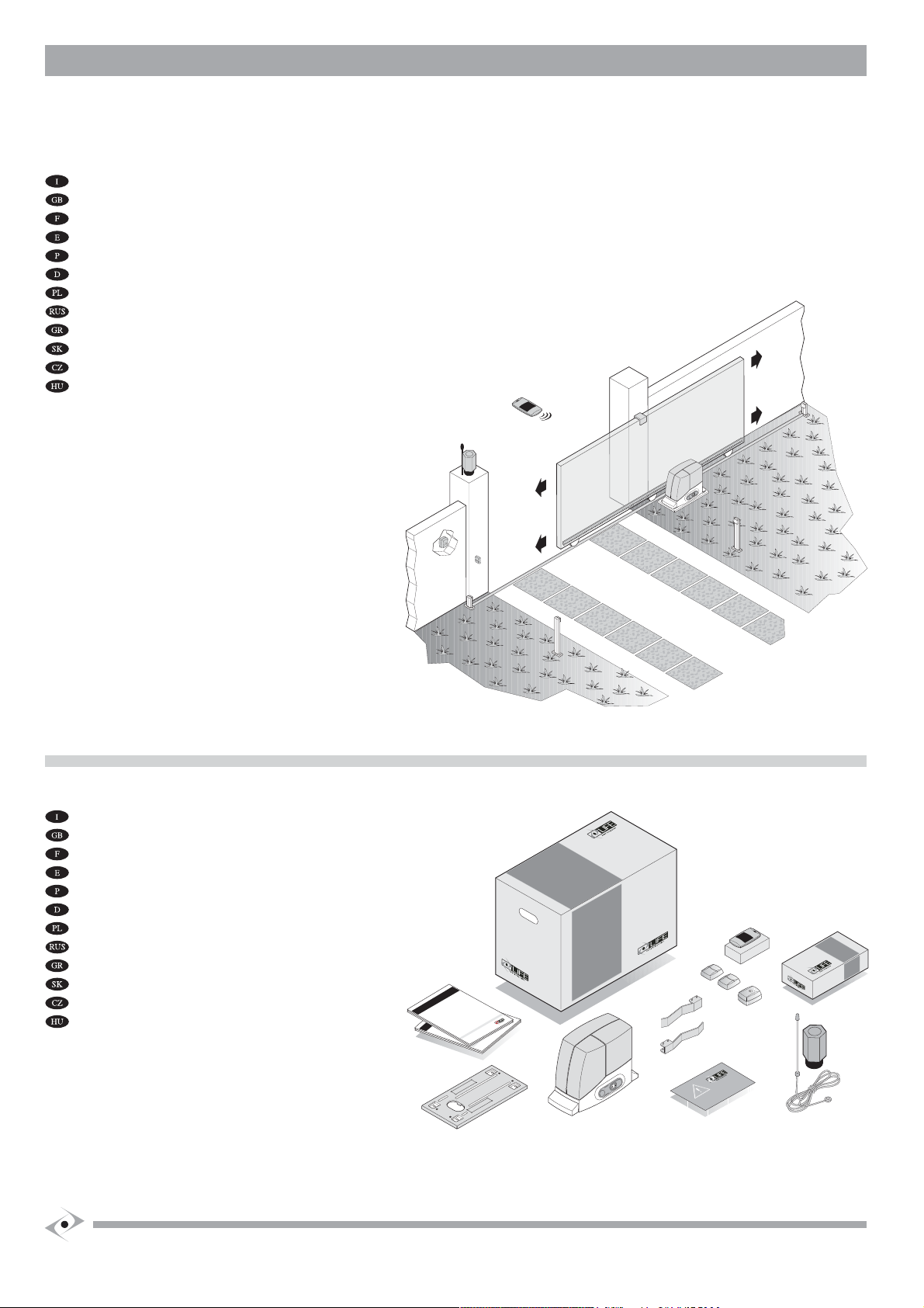
INTENDED USE
• ACER operators are designed for opening and closing residential-type sliding gates only. Improper use or use on gates larger than those indicated in the TECHNICAL DATA chapter will
be considered non-conform to the intended use. The Manufacturer declines all responsibility for improper use. The owner accepts full responsibility for improper use, which will result
in the warranty being rendered void.
• Any usage differing from that described above is forbidden.
• The operator may not be installed or used in potentially explosive environments.
• The Fitter must ensure that the environment in which the automation is installed is conform to the operator’s temperature range (see Technical Data chap.).
• The operator is not suitable for use on gates with built-in doors unless the automation is prevented from functioning when the door is open.
• Motorised gates must conform to current European standards and Directives, including EN 12604 and EN 12605.
• T
he operator may only be used when in perfect working order and in compliance with the intended use, in the awareness of safety and hazard conditions and in observance with the instructions for installation and use.
• Any dysfunctions that may pose threats to safety must be eliminated immediately.
• The gate must be stable, properly hung and resistant to flexion (it must not bend during opening and closure movements).
• The operator cannot compensate for faulty or incorrectly hung gates.
• The operator may not be used in environments prone to flooding
• Do not use the operator in environmental conditions characterised by harsh atmospheric agents (e.g. Salty air).
SAFETY INSTRUCTIONS AND WARNINGS
• These general rules must always be respected during the installation, connection, testing, trial run, use and maintenance of the automation.
• The Manufacturer declines responsibility for damage or injury caused by non-conformity with the information supplied concerning installation, trial run, use and maintenance contained
in this manual, and the failure to observe the safety instructions given below.
• The installation, connection, testing, trial run and maintenance of the operator must be performed by a COMPETENT PERSON aided and supervised by a PROFESSIONAL FITTER.
• Given the technical, procedural, regulation and legal implications of the work, unauthorised fitters are not permitted.
• Installation requires a practical and theoretical knowledge of mechanics, electronics and electrics, and of sector laws and standards.
• Amateur installation is strictly forbidden as it does not comply with current standards and laws and therefore does not guarantee the safe operation of the automation.
• Do not proceed with installation, connection and trial run in the event of doubts or indecision of any kind.
• This manual must be read carefully and understood before installing the operator. If doubts arise during installation, contact a PROFESSIONAL FITTER or the MANUFACTURER.
• Do not perform adjustments and/or parameter memorisation before installation is complete and only if you have understood the procedures described in this manual.
• O
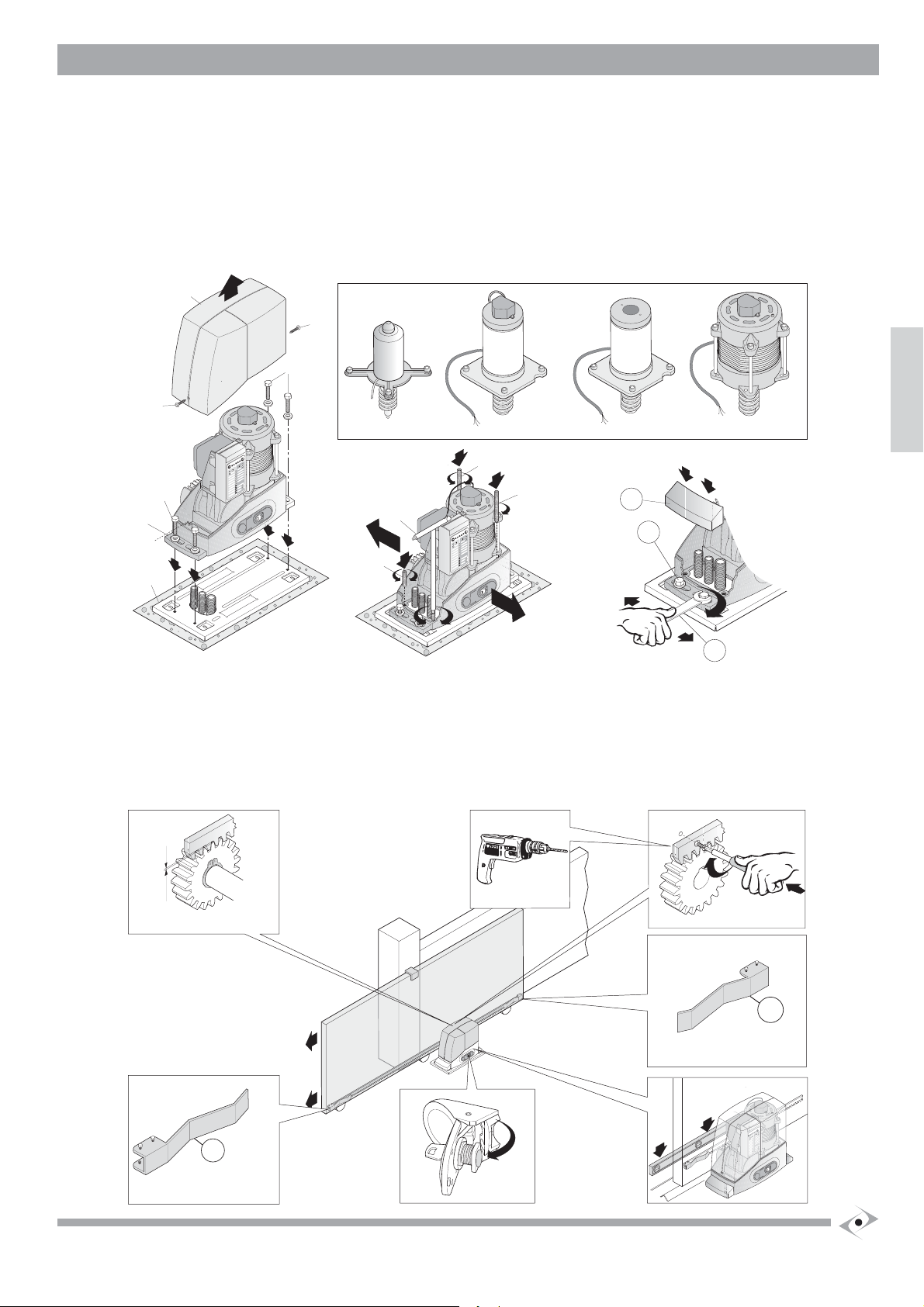
nly mount the operator on gates that are perfectly aligned with the sliding tracks and are properly hung. A gate that is not correctly aligned or hung can cause serious injury and/or damage to the operator.
• The Manufacturer declines all responsibility for damage and faults to the operator caused by non-observance of the instructions contained in this manual.
• Keep this manual in a safe and easily accessible place so that it can be consulted rapidly when necessary.
• During installation, connection, trial run and usage of the operator, observe all applicable accident prevention and safety regulations.
• In the interests of safety and optimal functioning of the operator, only use original spares, accessories, devices and fastening apparatus.
• D
o not perform alterations on any operator device or component. This type of operation may cause malfunctions. The Manufacturer declines all responsibility for damage caused by products that have been modified.
• The operator should not be used until the setting up procedure described in the STARTING UP chapter has been performed.
• S
hould liquids penetrate inside the operator, disconnect the electricity supply and contact the Manufacturer’s Assistance Service immediately; use of the operator in such conditions may cause hazard situations.
• In the case of faults or problems that cannot be resolved using the information contained in this manual, contact the Manufacturer’s assistance service.
Storage instructions and warnings
• The manufacturer declines all responsibility for damage and faults to operator functioning caused by non-compliance with the storage instructions given below.
• The operator must be stored in closed, dry places, at room temperatures of between –20 and +70°C.
• Keep the operator away from sources of heat and naked flames, which could damage it and cause malfunctions, fires or hazard situations.
• Keep the operator in a horizontal position, but not resting on the ground.
Indications and warnings for use
• It is the fitter’s duty to perform risk analysis and inform the user/owner of any existing residual risks. Any residual risk detected must be recorded in writing in this manual.
• T
he following residual risks are usually present in moving gates: impact and crushing against the main closure surface; impact and crushing in the opening area; shearing between sliding
leaf and fixed part of the track and support during movement; mechanical risks caused by movement.
• T
he Manufacturer will not accept responsibility for damage or injury caused by the non-observance of the information on use contained in this manual, and the failure to observe the safety
indications given below.
• The Manufacturer declines responsibility for damage and malfunctions caused by non-compliance with the instructions for use.
• Keep this manual in a safe, easily accessible place, so that it can be consulted rapidly when necessary.
• Never touch the gate or moving parts when they are in motion.
• Remain at a safe distance when the gate is in motion: only pass when the gate is completely open and immobile.
• Prevent children from playing or standing in the vicinity of the gate or the control organs (radio control), the same precautions should be adopted for disabled persons and animals.
• In the event of malfunctions (noisiness, jerky movements, etc.) suspend the use of the automation immediately: failure to observe this rule may entail serious hazards, risks of accidents and/or serious
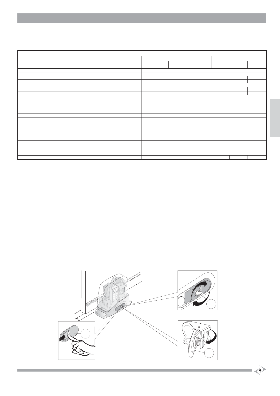
damage to the gate and the automation. Contact a PROFESSIONAL FITTER and in the meantime use the gate manually by disconnecting the operator (see the OPERATOR RELEASE chapter).
• In order to maintain the operator in efficient conditions, ensure that the operations indicated in the MAINTENANCE chapter are performed at the frequency indicated by a PROFESSIONAL FITTER.
• S
hould liquids penetrate inside the operator, disconnect the power supply immediately and contact the Manufacturer’s Assistance Service; the use of the operator in such conditions may cause hazard situations.
• If a problem arises that cannot be resolved using the information contained in this manual, contact the Manufacturer’s assistance service.

6
Instructions and warnings for installation
• Before commencing installation read the SAFETY INSTRUCTIONS AND WARNINGS chapter carefully.
• The person who installs the operator is responsible for performing risk analysis and regulating the automation’s safety devices consequentially.
• Before commencing installation, check whether further devices or materials are needed to complete the automation in order to suit the specific situation in which it will be used.
• It is strictly forbidden to motorise a gate that is not already efficient and secure as the automation cannot resolve faults caused by incorrect installation or poor maintenance of the gate.
• During installation, make constant reference to harmonised standards EN 12453 and EN12445.
• Ensure that the individual devices to be installed are suitable for the automation that one intends to create, paying careful attention to the points raised in the TECHNICAL DATA chapter. Do not proceed
if even just one device is unsuitable for the intended use.
• Ensure that the place of installation is not prone to flooding, does not contain sources of heat or naked flames, fires or hazard situations in general.
• During installation, protect automation components to prevent liquids (e.g. rain) and/or foreign bodies (earth, gravel, etc) penetrating inside.
Preliminary checks
Before commencing installation, the following preliminary checks must be performed:
1) The weight and dimensions of the gate must not exceed the limits for use (see the TECHNICAL DATA chap.), if they exceed such limits, the operator may not be installed.
2) The gate structure must be suitable for the installation of the operator and conform to current standards.
3) The gate’s movement in both opening and closure must be uniform, without points of greater resistance or friction.
4) The gate must be properly hung and without risks of derailment, this can be checked by sliding the gate back and forth several times.
5) The gate must be hung flat, i.e. it must not move when left in any point of the sliding tracks. Ensure that the gate does not bend or deviate from its course during movement.
6) The gate must be perfectly flat in to the plane to which the sliding track is fixed, in order to prevent irregular movement during operation.
7) The limit switches must be sufficiently sturdy and there must be no risk of derailment should the gate collide with the limit switches.
8) The operator installation area must not be prone to flooding and therefore it may not be installed in potholes, trenches, dips in the ground, etc.
9) The cement base on which the operator must be installed must be adequately solid and compact.
MAINTENANCE INSTRUCTIONS AND WARNINGS
• Once the automation has been tested, the parameters set must not be altered. If further adjustments (e.g. alterations to the voltage value) are made, all the checks required for testing
and compliance with standards must be repeated.
• The Manufacturer declines responsibility for damage or injury caused by non-compliance with the information provided in this manual and the safety instructions provided below.
• The Manufacturer declines all responsibility for damage and malfunctions deriving from non-compliance with the maintenance instructions.
• In order to keep the operator efficient and safe, follow the cleaning, checking and routine maintenance procedures as described in this manual. This is the owner’s duty.
• Any checking, maintenance or repair work must be conducted by a PROFESSIONAL FITTER
• Always switch of the electricity supply in the event of malfunctions, breakdowns and before any other operations in order to avoid the gate from being activated.
• The owner is not authorised to remove the operator lid as it contains live parts.
• If the power cable is damaged, it must be replaced by the Manufacturer or its technical Assistance service or in any case a person with a similar qualification in order to avoid risks.
• The owner is NOT authorised to use the programming keyboard.
• Use original pare parts, accessories and clamping material only.
• Do not perform technical or programming modifications on the operator. Operations of this type may cause malfunctions and/or risk of accidents. The Manufacturer declines responsibility for damage
deriving from modified products.
• In the event of intervention of automatic or fuse switches, before restoring function conditions identify and eliminate the fault. Request the intervention of a PROFESSIONAL FITTER.
• If a fault that cannot be solved following the information contained in the present manual, contact the manufacturer’s assistance service.
• All maintenance, repair or replacement of parts must be recorded in the maintenance log, which is SUPPLIED AND INITIALLY FILLED IN BY THE FITTER.
• Inspect the installation frequently to ensure that there are no signs of mechanical unbalance, wear or damage to the wires and assembled parts: no not use the automation until any necessary repairs
or adjustments have been made.
Cleaning the automation
ATTENTION:
• Never wash the operator using water sprays or washing devices.
• Do not use corrosive substances, solvents, thinners or spirit to clean the operator.
• Switch off the electricity supply to the operator before cleaning.
a) Automations are almost always installed outdoors and therefore they are subject to climatic variations and exposed to the elements, which transport debris that may cause problems.
b) The entire area in which the automation is installed must be kept clean to avoid malfunctions and/or faults.
c) Keep the track on which the gate runs clean by sweeping stones, gravel, and mud off using a broom.
d) C
lear the area in which the operator is installed to prevent stones, gravel, mud, dry leaves, pine needles etc. from accumulating around the pinion, thus causing damage to the pinion, rack, limit switch and operator.
Routine maintenance
Every six months contact a PROFESSIONAL FITTER to perform the following operations.
• A series of opening and closing checks using radio controls and selectors, using all the system’s components (photocells, flashing light, etc.). Ensure that the operator performs the desired action.
• Grease the operator’s nut-screw-bushing unit and the gate hinges.
• Repeat the series of tests envisaged for operator testing (see INSTALLATION MANUAL – Testing and first run chapter.
DEMOLITION AND DISPOSAL
ACER operators are constituted by various materials, which implicates different disposal modes. Materials such as aluminium, plastic, electric cables, etc., can be recycled; batteries, electronic cards,
etc. must be disposed of.
ATTENTION:
• The disposal of batteries, cards and electric and electronic components must comply with legislation and local regulations on toxic, harmful and polluting substances.
• Disconnection from the main supply must always be performed by a qualified electrician using suitable equipment.

SIAÇNARF
MANUFACTURER’S DECLARATION OF CE CONFORMITY
Declaration of Conformity
under Directive 98/37/EC, appendix II, part B (Manufacturer’s Declaration of CE Conformity).
LIFE home integration
Via 1 Maggio, 37
31043 FONTANELLE (TV) – Italia
declares that the following product:
ACER operator for sliding gates
Satisfies the essential requisites established in the following directives:
• Machinery Directive 98/37/EC (ex 89/392/EEC) and subsequent amendments,
• Low voltage directive 73/23/EEC and subsequent amendments,
• Electromagnetic compatibility directive 89/336/EEC and subsequent amendments,
• Radio and telecommunications equipment directive 1999/5/EC and subsequent amendments.
and satisfies the following standards
• EN 12445:2000 Industrial, commercial and garage doors and gates – Safety in the usage of motorised doors – testing methods.
• EN 12453:2000 Industrial, commercial and garage doors and gates – Safety in the usage of motorised doors - Requisites.
• EN 60204-1:1997 Machinery safety – Electric equipment of the machine – Part 1: general rules.
• EN 60950 Information technology equipment -Safety - Part 1: General requisites.
• ETSI EN 301489-3:2001 Electromagnetic compatibility for radio equipment and appliances.
• EN 300220-3:2000 Radio equipment and systems – short band devices – Technical characteristics and testing methods for radio apparatus with a
frequency of 25 to 1000 MHz and powers of up to 500mW.
The Manufacturer also declares that it is not permitted for the abovementioned components to be used until such time as the system in which
they are incorporated is declared conform to directive 98/37/EC.
Fontanelle Name of Signor: Faustino Lucchetta
Position: Managing Director
Signature: _____________________

3 A
15RI2310000 ACER 25RI2320000 AC4-AC6-AC8
35RI2330000 AC4R-AC6R
45RI2340000 AC4 24P
55RI2350000 AC8 24
65RI2360000 AC4M-AC6M-AC8M
75RI2370000 AC4RM-AC6RM
85RI2380000 AC8 24M
95RI2390000 AC4
10 5RI2400000 AC6
11 5RI2410000 AC8
12 5RI2420000 AC4R
13 5RI2430000 AC6R
14 5RI2440000 AC4 24P 15 5RI2450000 AC4 24
16 5RI2460000 AC6 24
17 5RI2470000 AC8 24
18 5RI2480000 ACER 19 5RI2490000 ACER M 20 5RI2500000 ACER
21 5RI2510000 AC4-AC6-AC4R-AC6R
22 5RI2520000 AC8-AC4 24-AC4 24P
AC6 24- AC8 24
23 5RI2530000 ACER 24 5RI2540000 AC4-AC6-AC4R-AC6R
25 5RI2550000 AC8-AC4 24-AC4 24P
AC6 24-AC8 24
26 5RI2560000 AC4-AC6-AC8-AC4R
AC6R

36 5RI2660000 ACER
37 5RI2670000 AC4R-AC6R-AC4 24P
38 5RI268000 ACER 39 5RI2690000 AC4-AC6-AC8
40 5RI2700000 AC4 24-AC6 24
41 5RI2710000 AC4 24P
42 5RI2720000 AC8 24
43 5RI2730000 AC4R-AC6R
30 5RI2600000 AC4-AC6-AC8-AC4R
AC6R
31 5RI2610000 AC4 24 P
32 5RI2620000 AC8 24
33 5RI2630000 AC4-AC6-AC8-AC4R
AC6R-AC4 24-AC6 24
34 5RI2640000 AC8 24-AC8 24M
35 5RI2650000 AC4 24P
27 5RI2570000 ACER 28 5R2580000 ACER 29 5RI2590000 ACER
4 A

4A
Address: Via Sandro Pertini,3/5 31014 COLLE UMBERTO (TV) Italia
Telephone: + 39 0438 388592
Telefax: + 39 0438 388593
http www.homelife.it
Table of contents
Languages:
Other LIFE home integration Gate Opener manuals
Popular Gate Opener manuals by other brands

SOMFY
SOMFY Dexxo RTS Pro INSTALLATION INSTRUCTIONS-ILLUSTRATIONS

SEA
SEA 1110 Important safety instructions

Zareba
Zareba G752 installation manual

Nice
Nice LFAB4024 Instructions and warnings for installation and use

RIB
RIB K1400 FAST Operating and installation instructions

Centurion
Centurion D2 Turbo user guide