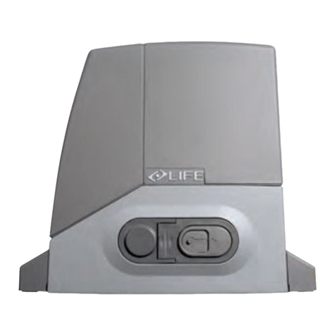
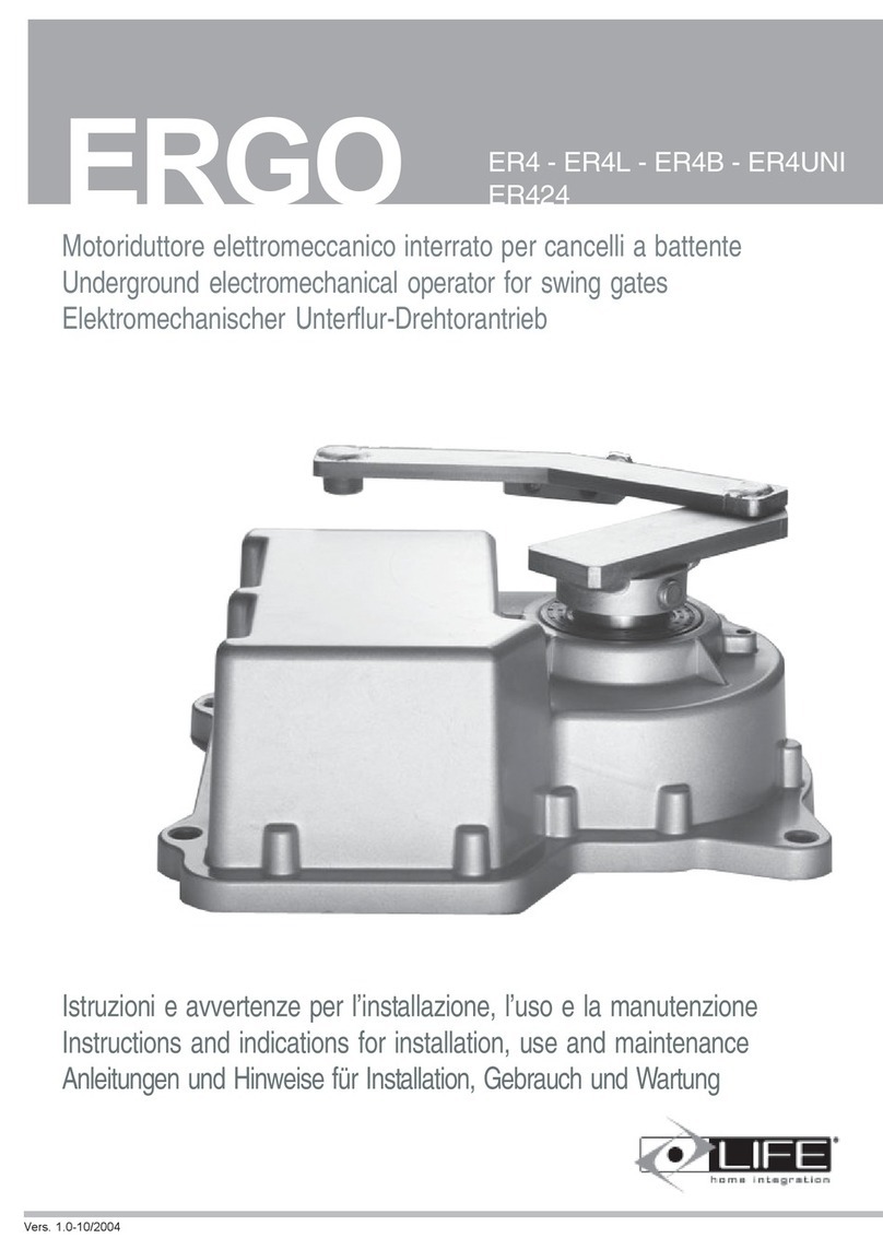
LIFE home integration OPTIMO OP3 Series Technical specifications

WWW.Roham-tech.ir
OP3-OP5
ИНСТРУКЦИИ и РЕКОМЕНДАЦИИ ПО МОНТАЖУ, ИСПОЛЬЗОВАНИЮ И ТЕХНИЧЕСКОМУ
ЛИНЕЙНЫЙ ЭЛЕКТРОМЕХАНИЧЕСКИЙ ИСПОЛНИТЕЛЬНЫЙ
INSTRUCTIONS AND WARNINGS FOR INSTALLATION, USE AND MAINTENANCEОБСЛУЖИВАНИЮ
LINEAR ELECTROMECHANICAL OPERATOR FOR SWING GATESСТВОРЧАТЫХ
INSTRUÇÕES E ADVERTÊNCIAS PARA A INSTALAÇÃO, USO E A MANUTENÇÃO
MOTOR LINEAR ELECTROMECÂNICO PARA PORTÕES DE BATENTE
INSTRUKCJA MONTAŻU, UŻYTKOWANIA I KONSERWACJIОБСЛУЖИВАНИЮ
МЕХАНИЗМ SIŁOWNIK LINEARNY ELEKTROMAGNETYCZNY DO BRAM
INSTRUCCIONES Y ADVERTENCIAS PARA LA INSTALACIÓN, EL USO Y EL
ACTUADOR LINEAL ELECTROMECÁNICO PARA CANCELAS
INSTRUCTIONS ET CONSEILS POUR L’INSTALLATION, L’UTILISATION ET
ACTIONNEUR LINEAIRE ELECTROMECANIQUE POUR PORTAILS A
ANLEITUNGEN UND HINWEISE FÜR INSTALLATION, GEBRAUCH UND WARTUNG
ELEKTROMECHANISCHER DREHTORANTRIEBСТВОРЧАТЫХ ВОРОТ
UTASÍTÁSUK ÉS FIGYELMEZTETÉSEK TELEPÍTÉSHEZ, HASZNÁLATHOZ ÉS KARBANTARTÁSHOZ
ELEKTROMECHANIKUS KAROS MEGHAJTÁS SZÁRNYAS KAPUKHOZ
ISTRUZIONI E AVVERTENZE PER L`INSTALLAZIONE, L`USO E LA MANUTENZIONE
ATTUATORE LINEARE ELETTROMECCANICO PER CANCELLI A BATTENTE

1
1 TECHNICAL FEATURES
2.0 INSTALLATION
The type of gate, height and shape of the leaf and climatic conditions impose certain limits of use and must be carefully taken
into consideration during installation. The following table is to be considered a rough guide.
860
OP5 corsa 450 mm
OP3 corsa 300 mm
D=OP3 775 mm
95
106
1010
D=OP5 905 mm
2.1 Limits of use
LIFE home integration reserves the right to make changes to technical characteristics at any time and without prior notice,
without changing the product’s intended use and function.
NAME OP3 OP3 UNI OP3L OP3L UNI OP5 OP5 UNI OP5L OP5L UNI OP324 OP324 UNI OP524 OP5 UNI
Motor power supply V 230 V ac 50 Hz 24V dc
Power W210 80
Input A1,3 3,5
Capacitor µF 8 NO
Thrust N2000 1800
Lubrication Type grease
Net rod travel mm 300 450 300 450
Thermal protection device °C 140 NO
Stop plate -YES - YES - YES - YES
- YES - YES
Electromechanical limit switches YES - YES -YES - YES - YES - YES -
Optic encoder YES NO YES NO YES NO YES NO YES NO YES NO
Connected cable CENELEC H07RN-F
Operating temperature °C from -20 to +70
Protection class IP 54
Speed m/min. 0,96 0,6 0,96 0,6 0,96 0,96
Time to open 90° S 19 30 28 45 19 28
Work cycle % 35 30 35 30 80 80
Nominal work time min. 10 7,5 10 7,5 20 20
Motor insulation class F D
Battery recharge time* h- 48
Opening cycles with
charged battery N° - 15 10
Operator weight kg 8,5
9,5 8,5 9,5
Total dimensions 95x106L=860 95x106L=1010 5x10⁶L=860 95x106L=1010
Use in acid, saline or potentially explosive environment NO
OPTIMO: Irreversible electromechanical operator with 230V or 24V power supply for swing gates with or without optical encoder,
with or without limit switches and with stop plates.
ENGLISH
WWW.Roham-tech.ir

2
OP3 - OP3L - OP3 UNI - OP3L UNI - OP324 - OP324 UNI OP5 - OP5L - OP5UNI - OP5L UNI - OP524 - OP524
2,00 800 3,00 500
2,50 600 4,00 400
3,00 400 5,00 300
EOP3= 745 mm
EOP5= 895 mm
80
2.2 Typical installation
A) TWO-LEAF SYSTEM
The denition of leaf 1 and leaf 2 of the gate is essential for automation operation.
Leaf 1: is the rst to open (1) when the gate is closed and the second to move when the gate is open; it nishes its closure travel after leaf 2.
Leaf 2: is the second to open (2) when the gate is closed and the rst to move when the leaves are open; it nishes its closure travel before leaf 1.
B) ONE-LEAF SYSTEM
Leaf 1: the gate’s only leaf.
2
1
1
2
12
AB
Max leaf length (m) Max leaf weight (kg) Max leaf length (m) Max leaf weight (kg)
WWW.Roham-tech.ir

3
Check that the distance “C” on the gate support structure is no greater than the value given in the table below. If the distance is higher than this value,
it is necessary to intervene by making a niche in the structure to obtain the indicated value. This is to avoid the linear operator colliding with the edge of
the structure during closure. The niche must be made in the area in which the linear operator is to be installed and it must have a height such as to allow
operator passage.
2.3 Rear and front bracket positioning
a) Dene the clamping position of the rear bracket (1) of the operator, observing
the distances A, B and C.
b) Check that the outlet of the pipe housing the electric cables is below the
bracket (1).
c) Check that there is enough space on the leaf, at the point in which the operator’s
front bracket is to be clamped, and that the surface is suitable for clamping (with
screws or by means of welding).
d) Fix (with screws or by means of welding) the rear bracket (1) to the pillar in the
established position.
e) Make sure that the rear bracket (1) is perfectly level.
a. Take the leaf to the closure position, resting it against
the closure stop plates.
b. Position the front bracket (2) at distance E from the rear
bracket (1) and 80 mm lower.
The value of Emust be just lower (10 mm) than D (maximum space between centres) to allow optimal stop plate adjustment.
a) Temporarily block the front bracket (2) with a clamp.
b) Check that the bracket is level using a spirit level.
OP324 UNI OP524 UN
Ω
OP3 - OP3L - OP3 UNI – OP3L UNI – OP324 OP5 – OP5L – OP5UNI – OP5L UNI – OP524
AMAXmm BMAXmm CMAXmm D*mm AMAXmm BMAXmm CMAXmm D*mm
Ω1=90° 140 140 90 max 755 210 210 140 max 905
Ω2=120° 140 100 50 max 755 210 120 70 max 905
1
1
12
2
EOP3= 745
EOP5= 895
80
1
A
B
D
C
Ω
Ω
1
2
E
A
A
B
B
C
OP3 - OP3L - OP3 UNI – OP3L UNI OP5 – OP5L – OP5UNI – OP5L UNI
OP324-OP324UNI OP5-OP5L–OP524 UNI
E 745 mm 895 mm
OPTIMO 3 OPTIMO 5
C
ENGLISH
WWW.Roham-tech.ir

WWW.Roham-tech.ir 4
2.4 Positioning the operator and stop plate adjustment
1. Release the operator as indicated in the RELEASING THE OPERATOR chapter.
2. Lift the operator and insert the nut screw bushing support pin (3) into the hole on the front bracket (2).
3. Insert the bushing (4) into the chosen hole on the rear bracket (1) and thread the operator fork (5) on to the bracket, aligning the hole with the
bushing. Fix the whole set with a screw, washer and self-locking nut and tighten.
4. Fix the operator to the front bracket (2) using a screw and washer, and tighten.
5. Manually open and close the gate several times and check that the movement of the leaf is regular and that the operator moves on a plane parallel
to the gate’s plane of movement.
6. Check that the nut screw bushing support (3) slides perfectly on the operator nut screw and that, with the leaf closed and open, there are at least
5 mm between the nut screw bushing support (3) and the closure (6) and opening (7) stop plates.
7. If necessary, use a different hole on the rear bracket and repeat the operations indicated in points 3 and 4. .
8. Dene with precision the opening and closure positions of the stop plates on the operator’s internal slider, as follows:
• take the gate to a closed position, abutting against the stop plate.
• loosen the support of the closure stop plate (6) using a suitable wrench and position so that it touches the nut screw bushing support (3); then
lock again by tightening.
• Take the gate leaf to the desired opening position;
• loosen the support of the opening stop plate (7) using a suitable wrench and position so that it touches the nut screw bushing support (3); then
lock again by tightening.
9. Denitively x the front bracket (2) of the operator, to the leaf of the gate, choosing the clamping means to suit the material of the leaf (with screws
or by welding).
10. Release the operator as indicated in the RELEASING THE OPERATOR chapter.
2.5 Releasing the operator
ATTENTION:
• The tter must permanently x the label describing the manual release operation close to the manual release key.
• The activation of the manual release could cause an uncontrolled movement of the gate in the event of mechanical damage or
mechanical unbalance conditions.
• Before performing the manoeuvre, switch off the electricity supply to the automation.
• To avoid breaking the key, do not apply excessive force.
This command makes it possible to release the operator transmission and to perform leaf movement manually. It can be used in the case of a blackout or
system malfunction.
The release is activated using a wrench, which must be kept in a safe place.
36
7
36
7
2
3
4
1
5
1
5
a) Lift the lock protection cover (1).
b) Insert the key (2) into the lock and turn clockwise through 360°.
c) The leaf is now free and can be moved manually.
d) To relock the leaf, insert the key (2) and turn anticlockwise through 360°.
1
2
360°
2
360°
BLOCCAGGIO
SBLOCCAGGIO

WWW.Roham-tech.ir 5
3.0 WIRING AND CONNECTIONS
• Before commencing wiring and connection work, read the SAFETY INSTRUCTIONS AND WARNINGS chapter carefully.
• The operator must be connected to Life control units only.
• All wiring and connection operations must be carried out with the control unit disconnected from the electricity supply. If the
disconnection device is not in view, display a sign reading: “ATTENTION: MAINTENANCE WORK IN PROGRESS”.
• The internal wiring of the linear electromechanical operator performed by the Manufacturer, may not be modied under any circumstances.
3.1 Electrical connections of the operator
One or two cables lead out of the operator depending on whether or not one has the UNI version.
The UNI single-cabled version, only has a power supply cable, which can be 230 V (cable with 4 wires) or 24 V (cable with two wires).
The 230 V and 24 V two-cabled versions have an extra cable for the encoder and limit switch signal (2-wired cable).
The 230V models come with a capacitor, which is housed in the control unit. The capacitor is connected in parallel to the “open motor” and “close
motor” cables.
OP3 UNI-OP3L UNI
OP5 UNI-OP5L UNI
D
C
F
E
OP324 UNI-OP524 UNI
G
H
I
N.B. each cable is 1m long.
OP3 - OP3L - OP5 - OP5L
OP3 UNI - OP3L UNI - OP5
UNI - OP5L UNI
OP324 - OP524
OP324 UNI - OP524 UNI
230 V
50 Hz
24 V
LIMIT SWITCH and ENCODER SIGNAL
MOTOR POWER SUPPLY
BLUE/ GREY COMMON BROWN +
BLACK OPEN MOTOR BLUE -
BROWN CLOSE MOTOR
YELLOW - GREEN EARTH
BLUE + BROWN +
BROWN - BLUE -
YELLOW - GREEN EARTH
OPERATORS
OP3 - OP3L - OP5 - OP5L GE1A -GE2A GE1R -GE2R
OP3 UNI - OP3L UNI - OP5 UNI - OP5L UNI GE UNI R
OP324 - OP524 GE1A 24 GE1A 24-GE2A 24
OP324 UNI - OP524 UNI GE UNI 24R
230 V
50 Hz
24 V
OPERATORS
D
C
FE
A
B
OP3-OP3L-OP5-OP5L
H
G
I
A
B
OP3 24-OP5 24
LIFE PLUG-IN RADIO
RECEIVER INTEGRATED 433.92 MHz
RADIO RECEIVER
ENGLISH

WWW.Roham-tech.ir
1-2
1) 5RI0870000 OP3-OP5-OP3UNI-OP5UNI
2) 5RI0880000 OP3L-OP3LUNI-OP5L-OP5LUNI
3
3) 5RI0890000 OP324-OP324UNI-OP524-OP524UNI
4-5
4) 5RI0900000 OP3-OP3UNI-OP3L-OP3LUNI-OP324-OP324UNI
5) 5RI0910000 OP5-OP5UNI-OP5L-OP5LUNI-OP524-OP524UNI
6
6) 5RI0920000 OPTIMO
7
7) 5RI0930000 OPTIMO
8
8) 5RI0940000 OP3-OP3L-OP5-OP5L-OP324-OP524
9-10
9) 5RI0950000 OP3-OP3L-OP3UNI-OP3LUNI-OP5-OP5L-
OP5UNI-OP5LUNI
10) 5RI0960000 OP324-OP324UNI-OP524-OP524UNI
11-12
11) 5RI0970000 OP3-OP3L-OP324
12) 5RI0980000 OP5-OP5L-OP524
ОПИСАНИЕ ОСОБЕННОСТЕЙ OP3 / OP5
DESCRIPTION OF OP3/OP5 COMPONENTS
DESCRIPTIONS PARTICULIERES
OP3 / OP5
OPIS SZCZEGÓŁOWY OP3 / OP5
DESCRIPCIONES DE LOS DETALLES
DEL OP3 / OP5
DESCRIÇÕES PARTICULARES OP3 / OP5
BESONDERE BESCHREIBUNGEN
OP3 / OP5
OP3/OP5 RÉSZLETEZETT ROBBANTOTT
LEÍRÁSA
DESCRIZIONE COMPONENTI OP/OP5

15-16 17
22
19
20 21
15) 5RI01010000 OP3-OP3L-OP324
16) 5RI01020000 OP5-OP5L-OP524
17) 5RI01030000 OPTIMO
18) 5RI01040000 OPTIMO 19) 5RI01060000 OPTIMO
20) 5RI01070000 OPTIMO 22) 5RI01080000 OP3-OP3L-OP3UNI-OP3LUNI-OP5-OP5L
OP5UNI-OP5LUNI
22) 5RI01090000 OPTIMO
18
23
23) 5RI2750000 OP3UNI-OP3LUNI-OP324UNI-OP5UNI
OP5LUNI-OP524UNI
13
13) 5RI0990000 OPTIMO
14
14) 5RI01000000 OPTIMO
WWW.Roham-tech.ir
This manual suits for next models
13
Table of contents
Other LIFE home integration Gate Opener manuals
Popular Gate Opener manuals by other brands

SOMFY
SOMFY AXOVIA 3S INSTALLATION INSTRUCTIONS-ILLUSTRATIONS

FAAC
FAAC S800H SB manual

cedamatic
cedamatic RAM 50V Series Operating instructions and spare parts catalogue

CAME
CAME STYLO instruction manual

Comunello Automation
Comunello Automation DART installation manual

Chamberlain
Chamberlain LMWEKITU manual