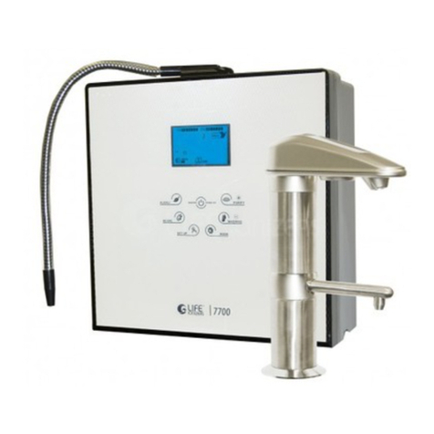
Life 7600/ 8100/ 8200 User manual


Safety Guide
Installation of Parts Guide
Installation Instructions
Installation Guide
Indicator Functions
Operation Method
Parts of the Ionizer
Operation Warnings
Production of Ionized Water
7600 to 8100 Conversion
Operation Warnings
Installation Guide for 8100
Operation Method
Indicator Functions
Installation of the Pre-Filter
Internal Filter Replacement
Filters
Explanation of Ionized Water
Alkaline and Acidic Water Usage Guide
Uses of Ionized Alkaline/Acidic Water
Performance Features
Common Problems and Solutions
Acidic Cleaning Instructions
& Routine Maintenance
Frequently Asked Questions
4-8
9
10
11
12
13
14
15
16
17
18
19
20
21
22
23
24
25
26
27-29
30
31-32
33
34-45
Table of Contents

www.LifeIonizers.com/Support
4
Safety Guide - Read Completely
Before installation or operation of the LIFE IonizerTM, read this
instruction manual completely.
Note- Some parts may have been altered to improve product quality,
function or ease of use.
Symbols
Indications
Refer to the following key symbols and indicators throughout the manual.
Improper use may cause bodily injury
Improper use may cause structural damage to the unit
or physical injury
Caution, warning, danger symbol
Information on prohibited functions and uses
Make note of important information
Do not open as it may cause electric shock or other injury
Disconnect power plug in case of malfunction
75
7600/8100/8200
As with most electrical appliances, electrical parts in
this ionizer are electrically live even when switch is o.

www.LifeIonizers.com/Support 5
Improper use may cause bodily injury
When drinking Ionized Alkaline Water - Do not take
prescription or other medications for approximately one
hour before and after drinking water.
This machine should not be repaired or otherwise
disassembled by any unauthorized person as it
may cause electrical re or shock, and will void the
manufacturer’s warranty.
Do not place the machine in humid areas such as
bathrooms. Do not clean this machine by spraying
the ionizer with water as it may cause electrical
shock.
75
7600/8100/8200
As with most electrical appliances, electrical parts in
this ionizer are electrically live even when switch is o.

www.LifeIonizers.com/Support
6
Power cord should not be touched with wet hands.
Power cord should be plugged directly into an electrical
outlet.
Do not connect multiple appliances into a single power
receptacle.
Dusty or dirty electrical outlets may cause safety issues.
Bending, twisting, pulling or putting heavy objects onto
the power cord may cause electrical problems including
re.
If power cord, plug, or electrical outlet are damaged,
discontinue use immediately.
If the ionizer machine falls into water-
1. Unplug power cord from electrical outlet
2. Wipe the machine down and place in shaded area
3. Contact your LIFE IonizerTM dealer
Use only (110v) in the U.S.A. and Mexico. Use (100v) in
Japan. Most other countries require (220v). The power
cord cannot be altered from manufacturer’s specs.
Do not crimp or staple the power cord as it could cause
electrical shock.
75
7600/8100/8200
As with most electrical appliances, electrical parts in
this ionizer are electrically live even when switch is o.

www.LifeIonizers.com/Support 7
Improper use may cause bodily injury
Improper use may cause structural damage to
the unit or physical injury
Place machine in an upright position only.
If not used for several days, run water through the
unit for 1 to 3 minutes before starting.
Do not install this unit in direct sunlight or near a
heater, replace or other heat source.
Do not use water with a temperature of over 104
degrees Fahrenheit or 40 degrees Celcius.
Store Ionized Alkaline Water in an air-tight glass
container and refrigerate for up to 2 days.
If inexperienced with drinking Ionized Alkaline
Water, users are encouraged to start with lever 1.
DO NOT DRINK ACIDIC WATER.
If wall mounted, secure rmly and correctly.
Do not store Alkaline or Acidic water in metal
containers.
75
7600/8100/8200

www.LifeIonizers.com/Support
8
Aluminum and brass containers will be tarnished by
Alkaline and acidic water.
Improper use may cause structural damage to the unit
or physical injury
Do not block the unit vent as it can cause overheating
and/or electrical problems.
Do not use benzene, thinner, or chemicals to clean the
unit as it can damage the housing.
Do not block the water passage or tubing.
If the machine will not be used for several days...
1. Unplug the power cord from the electrical outlet
2. Turn o the water valve to avoid leaking
3. Remove lters, drain and place in refrigerator in
plastic bags.
When handling the pH test (reagent drops)
1. Keep away from eye area. If eyes become irritated,
ush thoroughly and consult a doctor.
2. If accidentally swallowed, drink water and consult a
doctor.
3. Store in an airtight container away from the reach of
children.
4. Drops are ammable. Keep away from children.
75
7600/8100/8200

www.LifeIonizers.com/Support 9
1. Refer to the diagrams on the following page before beginning
installation.
2. Be aware that a 110v outlet (USA) or 220v outlet is required. If
the outlet is located under the sink, make sure it is not near
the water source.
3. If after installation the water has an odor, you may need to
install a pre-lter. Please consult your LIFE IonizerTM dealer.
4. How to use reagent drops. (BTB Chemical). Put 2-3 drops in
approximately 1 ounce of water to be tested. Compare color
to color chart provided in kit to determine pH level.
EXTRA
FUSE
Reagent Drops
(pH Test Drops)
Flexible Hose
Wall - Mount Nail Tubing Hose
Diverter User Manual
BTB Chemical
Installation of Parts Guide
(for 8100)
Diverter Valve
75
7600/8100/8200

www.LifeIonizers.com/Support
10
Installation Instructions for LIFE IonizerTM 7600
Use Cold Water Only With Your Ionizer
STEP 1: Unscrew the existing aerator from your faucet.
STEP 2: Use teon plumbers tape on the threads. Screw the LIFE
IonizerTM diverter valve onto your faucet. Three dierent
sized adaptors are included for non-standard sized faucets.
STEP 3: Unscrew the round nut from the side of the diverter valve.
Slide the nut over the end of the 1/4” tubing and then screw
the nut back onto the diverter valve. Tubing should now t
snugly onto the diverter valve.
STEP 4: Lay the ionizer down on its back and you will see two white
elbows extruding from the bottom of the machine. There
will be an o-white collar around the base of the elbow.
Depress the collar towards the machine while simultaneously
extracting the elbow from the machine. Now, holding the
elbow in your hands, you’ll see a similar collar near the end
of the elbow. In the same way as you extracted the elbow,
you can depress the collar towards the elbow and extract
the plug from the end of the elbow. It is sometimes helpful
to use the back of a butter knife or screw driver to remove
the plug. If you ever need to remove the tubing from the
quick release, you will use the same process.
STEP 5: Run tubing from the diverter valve to the inlet valve on the
bottom of the ionizer. Be sure to push the tubing into the
quick connect valve 3/4” until it is rmly seated.
STEP 6: Insert one end of tubing into outlet valve on bottom of unit
and run the other end into the sink securing it with the
suction cup provided. Some units may contain water.
Don’t be alarmed; we test units for quality before shipment!
* For installation video, go to http://www.lifeionizers.com/support/LIFE Ionizer 7600 & 8100
75
7600/8100/8200

www.LifeIonizers.com/Support 11
Installation Instructions for LIFE IonizerTM 7600
C
o
ld
w
a
t
e
r
in
le
t
C
o
ld
w
a
t
e
r
i
n
l
e
t
Assembly method of valve for
wall-mounted water taps
Fix adapter
Quarter turn
for Tap Water
Running
Water
Rubber Gasket
Remove the aerator from the water tap.
Assembly method of valve for Deck-sink water taps
Screw in the adaptor
Remove the aerator from
the water tap.
Connect by rotation
after insertion of rubber
packing
Installation Guide
Cold Water inlet
Assembly method of valve for Deck sink water taps
Assembly method of valve for
wall-mounted water taps
Quarter turn
for Tap Water
Running
Water
Cold Water inlet
Rubber Gasket
Fix adapter
Inlet Valve
Outlet Valve
(Drainage)
75
7600/8100/8200

www.LifeIonizers.com/Support
12
Water Cleaning
Voice Functions
Ionized Alkaline Water
Acid Water Button
Puried Water Button
1. Drinking method indicator
2. pH indicator
3. Indicates “Being Washed”
4. Rotates while cleaning
5. Indicates ion water type
(Alkaline, acidic, puried)
6. Indicates selected
ionization water setting
7. Filter life - indicator
8. LIFE IonizerTM Logo
*Please wait a few seconds… as the machine is cleaning itself.
*4th grade of Ionized Alkaline Water is being extracted now.
*3rd grade of Ionized Alkaline Water is being extracted now.
*2nd grade of Ionized Alkaline Water is being extracted now.
*1st grade of Ionized Alkaline Water is being extracted now.
*2nd grade of acid water is being extracted now.
*1st grade of acid water is being extracted now.
*1st grade of clean water is being extracted now.
Voice: Please wait a few seconds as the machine is cleaning itself.
Indicator Functions
6
75
7600/8100/8200

www.LifeIonizers.com/Support 13
When “CLEAN WATER” is
selected, pH is not indicated.
The “ALKL” and “ACID” LEDs
go o.
When “Alkaline” water is
chosen, Levels 1 to 4 can be
selected by pressing the
“Alkaline” button again.
When “ACID WATER” is
selected, Level 1 or 2 can
be selected by pressing the
“ACID WATER” button again.
When “FUNCTION” is selected,
The menu changes from the
main menu to FN1 and FN2 and
then back to the main menu.
When replacing the lter while
on the main menu, press the“1ST
FILTER”or“2ND FILTER”button
and hold for 5 sec. This resets the
lter counter to 0000. The lter
count goes to 9999.
When FN2 is selected with the
“FUNCTION”button, the amperage
setting can be adjusted from 0
to 4 by pressing the ”2ND FIL-
TER” (increase) and “1ST FILTER”
(decrease) buttons.
FN1 is the volume menu.
Levels 0 to 4 can be selected
by pressing the ”2ND FILTER”
(up) and “1ST FILTER” (down)
buttons to increase or decrease
the volume.
Operation Method
75
7600/8100/8200

www.LifeIonizers.com/Support
14
345
1. First Filter Cover
2. Wall Mount Screw
Holes
3. Speaker
4. Bar Code and Serial
Number
5. Second Filter
1. Outlet valve
2. Inlet valve
3. Power Plug
4. Fuse Box
5. On/O Power Switch
Parts for the Ionizer (Back)
Parts for the Ionizer (Bottom)
xxx-xxxxx-xx-xx
Parts of the Ionizer
75
7600/8100/8200

www.LifeIonizers.com/Support 15
Parts for the Ionizer (Front)
1. Water Spout
2. Water Hose
3. Flexible Hose
Connector
4. Control Panel
5. LCD panel
DO NOT run the following types of water though the LIFE
IonizerTM as it can cause damage to the unit.
1. Dirty or Salty Water
2. Water containing high amounts of rust or iron
3. Water above 40 degrees C or 104 degrees F
Read these instructions thoroughly before attempting
installation.
Operation Warnings
75
7600/8100/8200

www.LifeIonizers.com/Support
16
1. Press the main water ow
button on top of the product.
2. Select the water type –
Alkaline, Acidic, or Puried
setting.
3. When the “Alkaline” is selected,
the LCD indicates the Alkaline
setting and level.
When you select the main
water ow button while the
water pressure is low or valve
is closed, the LCD will appear as
“Fig. 1” Please check the water
pressure or valve opening before
proceeding.
4. According to the selected step,
the LED indicates the pH of the
water.
“ERR 1” will appear as shown in Fig. 1 if water pressure is low.
Please check...
Production of Ionized Water
75
7600/8100/8200

www.LifeIonizers.com/Support 17
“ERR 1” will appear as shown in Fig. 1 if water pressure is low.
Please check...
1. Snap in plastic adaptor into top of unit where exible metal hose was in place.
2. Cut a piece of 1/4 inch tubing and connect it to plastic adaptor on top of unit,
then insert other end of tubing into the alkaline tubing connection on faucet.
3. Connect a piece of 1/4 inch tubing from “outlet” on bottom of ionizer, to the
acid connection on faucet.
4. Plug in electrical extension wire into faucet connection and plug in the other
end into the back of the ionizer.
5. Press power button on top of faucet to turn on ionizer.
345
1. Outlet valve
2. Inlet valve
3. Power Plug
4. Fuse Box
5. On/O Power Switch
Conversion from 7600 to 8100
75
7600/8100/8200

www.LifeIonizers.com/Support
18
DO NOT run the following types of water though the LIFE
IonizerTM as it can cause damage to the unit...
1. Dirty or Salty Water.
2. Water containing high amounts of rust or iron.
3. Water above 40 degrees C or 104 degrees F.
Read these instructions thoroughly before attempting
installation.
Operation Warnings
A
Ionizer Parts List and Installation Guide
1. Refer to the diagrams on the following page before beginning
installation
2. Be aware that a 110v outlet (US) or 220v outlet is required. If this
outlet is located under the sink make sure it is not near the water
source.
3. If after installation the water has an odor, you may need to install a
pre-filter. Please consult your Life Ionizer dealer.
DO NOT run the following types of water though the Life Ionizer as it
can cause damage to the unit:
1. Dirty or Salt Water
2.Water containing high amounts of rust or iron
3.Water above 40 degrees C/104 degrees F
Read these instructions thoroughly before attempting
installation
1- Acid Water Spout
2- Digital Indicator
3- Alkali Water Spout
4- Control Panel
1- Water Spout
2- Digital Indicator
3- Water Spout
4- Control Panel
Please note that water will come
out of both spouts when dispensing
water.
A) When the Alkaline button is
pressed, Alkaline water will be
dispensed from the top spout and
acid water will be dispensed
from the bottom spout.
B) When the Acid button is pressed,
Acid water will be dispensed from
the top spout and Alkaline water
will be dispensed from the bottom
spout.
C) When the purify button is pressed,
puried water will be dispensed
from the bottom and top spouts.
75
7600/8100/8200

www.LifeIonizers.com/Support 19
How to Connect the Angle Stop Adapter Valve
1. Shut o cold water supply by turning supply valve in
the o direction.
2. Disconnect supply valve from cold water supply hose.
DO NOT connect this unit to the hot water supply.
Ensure that the sealing gasket is fully seated into the
Angle Stop Valve female thread.
3.Install Angle Stop Adapter Valve on supply valve.
4. Connect the Angle Stop Adapter Valve to cold water
supply hose.
5. Connect white tubing to cold water diverter value.
Water ow adjustment screw is located opposite side of
white tubing.
6.Lay the ionizer downonits back and youwillseetwo white el-
bowsextruding from thebottomof the machine. Therewillbe
an off-white collararoundthebaseofthe elbow. Depressthecol
lar towardsthemachinewhilesimultaneously extractingthe
elbow fromthemachine. Now, holding the elbow inyour hands,
you’llseeasimilar collar neartheend of the elbow. In thesame
wayasyou extracted the elbow,you can depressthecollar to
wards theelbowand extractthe plug fromthe end oftheelbow.
Itissometimes helpful touse the back ofa butter knifeor screw
driver toremove theplug. Ifyouever need toremovethe tubing
from thequickrelease,youwillusethesameprocess.
Note- If installing a pre-lter, the pre-lter should be installed
between the cold water supply and the water inlet valve at the
bottom of the unit. See diagram and instructions on page 22.
7.
Installation Guide for 8100
* For installation video, go to http://www.lifeionizers.com/support/LIFE Ionizer 7600 & 8100
Connect the other end of the tubing from
the SpeedtTM side of the valve to the
water inlet (white elbow-quick connect)
located on the bottom of the ionizer.
Push the tubing into the elbow as far as
you can; approximately 3/4 of an inch.
The tubing and the elbow will self-seal.
If your sink/counter does not have a
hole for the faucet, select a location and
drill a 1 3/8 in. hole.
Place the faucet through the drilled
hole. From under the sink slip washer and
nut over the tubing and screw on tightly
to bottom of counter.
On the top of the machine, you will no-
tice there is a white plug in the ALKALI inlet
and there is a white plug in the ACID inlet.
These two plugs need to be removed
before you can install the tubing. On the
machine, there is a collar just under the top
of the plug. Depress the collar towards the
machine while simultaneously pulling the
plug out the machine. It is sometimes help-
ful to use the back of a butter knife blade or
a very thin, at screwdriver to push down
on the collar while you pull out the plug.
8.
9.
Connect the thicker tubing
running from the faucet
to the alkali connector at
the bottom of the unit, the
thinner tube to the acid
connector, and the electrical
connection to the back of
the unit.
10.
11.
345
1. Outlet valve
2. Inlet valve
3. Power Plug
4. Fuse Box
5. On/O Power Switch
1. 2. 3.
4. 5.
75
7600/8100/8200

www.LifeIonizers.com/Support
20
Operation Method
When you select alkaline water.
1~4 phases appear in number
and light is marked by blue
color.
When you select acid water,
1~2 phases apear in number
and light is marked by orange
color.
When you select puried water,
the number and light is marked
by green color.
The lifetime of the lter is
shown by four phases of light.
You should change the lter
when only one bar is not lit up.
* After changing the rst lter, you
can reset it by pushing the
acid button for 5 seconds.
* After changing the second lter;
you can reset it by pushing the
alkali button for 5.
For sound control, all alkaline,
acid, puried water lights will be
turned on if you push the puried
button for 5 seconds. After that, if
you push the acid button, the vol-
ume will decrease. If you push the
alkaline button, the volume will
be increase. This can be controlled
from 0 to 5 seconds.
DISPLAY WINDOW OPERATION MENU DESCRIPTION
Early stages of lter life. In need of lter change.
75
7600/8100/8200
Table of contents
Other Life Water Filtration System manuals
Popular Water Filtration System manuals by other brands

Streamline
Streamline FILTERPLUS FH0618-K instruction manual

tom logisch
tom logisch enteron user manual

Pulsotronic
Pulsotronic MESEP VA digital 50 manual

Philips
Philips IronCare GC024 user manual

GRE
GRE AR-135 Installation and maintenance manual

Maxblue
Maxblue Brita Intenza MB-C01 installation instructions