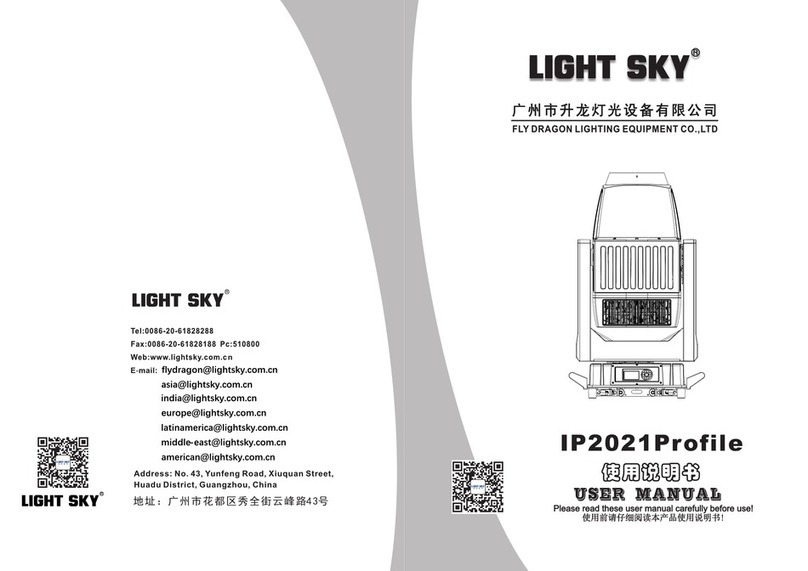
Light Sky SUPER SCOPE User manual

SUPER SCOPE MAX

-1-
CONTENTS
1. Safety Instructions...........................................................................................................2
2. Technical Specifications .................................................................................................5
2.1 Attachment And Size .............................................................................................8
3. Control Panel ...................................................................................................................9
4. Effect Wheels....................................................................................................................10
4.1 Replacing Rotating Gobos....................................................................................11
5. How To Set The Unit.......................................................................................................13
5.1 Main Function........................................................................................................13
5.2 Home Position Adjustment .................................................................................20
6. Control By Universal DMX Controller .........................................................................26
6.1 DMX 512 Connection...........................................................................................26
6.2 Channel Setting....................................................................................................27
6.3 Address Setting ...................................................................................................27
6.4 DMX 512 Configuration........................................................................................28
7. Electrical Connection Diagram......................................................................................36
8. Error Information............................................................................................................37
9. Troubleshooting..............................................................................................................43
10. Fixture Cleaning............................................................................................................44
Congratulations on choosing our company product! We thank you for your custom.
◆Please note that this product, as all the others in the rich my company range, has been designed and
made with total quality to ensure excellent performance and best meet your expectations and requirements.
◆Carefully read this user manual in its entirety and keep it safe for future reference.It is essential to know
the information and comply with the instructions given in this manual to ensure the fitting is installed, used
and serviced correctly and safely.
◆My company disclaims all liability for damage to the fitting or to other property or persons deriving from
installation, use and maintenance that have not been carried out in conformity with this user manual, which
must always accompany the fitting.
◆My company reserves the right to modify the characteristics stated in this user manual at any time and
without prior notice.
11. Duty exonerative and copyright protectio..................................................................44

-2-
1.Safety Instructions
WARNING
Important:
Damages caused by the disregard of this user manual are not subject to warranty.
The dealer will not accept liability for any resulting defects or problems.
►Unpack and check carefully to ensure that there is no transportation damage before
using the unit.
►This product is for indoor use only. Use only in a dry location.
►DO install and operate by qualified operator.
►The light source in this luminaire should be replaced by the manufacturer or its service
agent or a similarly qualified person, always cut off the power supply before replacing
he light source.
►DO NOT allow children to operate the fixture.
Please read the instruction carefully which includes important information about
the installation, usage and maintenance.
Please keep this User Manual for future consultation. If you sell the unit to another user,
be sure that they also receive this manual.
The following symbols are used to identify important safety information on the product
and in this manual:
Applies only to
luminaires directly
mounted on
surfaces of
non-combustible
materials
Replace all
shatter shields
Take a short
distance from
the object to be
photographed
(meters)
Rated
maximum
ambient
temperature
Indoor use
only
Do not point
the lens towards
the sun or
strong light
Operation not
allowed during
runtime
Hazardous
voltage.Risk
of severe or lethal
electric shock.
Safety hazard.
Risk of severe
injury or death.
Refer to manual
betore installing,
powering or
servicing.
Fire hazard. Burn hazard.
Hot surface.
not touch.
Do not touch
Risk of eye
injury.Safety
glasses must
be worn.
Risk of hand injury.
Safety gloves
must be worn.

-3-
►The unit must be installed in a location with adequate ventilation, at least 20cm from
adjacent surfaces.
►Be sure that no ventilation slots is blocked, otherwise the unit will be overheated.
►Before operation, ensure that you are connecting this product to the proper voltage in
accordance with the specifications in this manual or on the product’s specification label.
►It’s important to ground the yellow/green conductor to earth in order to avoid electric shock.
►Minimum ambient temperature TA: -10℃. Maximum ambient temperature TA: 40℃.
Do not operate this product at a lower or higher temperature.
►DO NOT connect the device to any dimmer pack.
►When the lamp is running, do not place combustible objects next to it. The shortest
distance between the device and inflammable and explosive objects or materials is 0.5m.
►Make sure the power cord is not crimped or damaged; replace it immediately if damaged.
►Unit’s surface temperature may reach up to 80℃. DO NOT touch the housing
bare-handedduring its operation.
►Avoid any flammable liquids, water or metal from entering the unit. Once it happens,
cut off the mains power immediately.
►DO NOT operate in a dirty or dusty environment. DO clean the fixture regularly.
►DO NOT touch any wire during operation as there might be a hazard of electric shock.
►Avoid entanglement of the power cord with other wires.
►The minimum distance to objects/surface must be more than 3 meters.
►In the event of serious operating problem, stop using the unit immediately.
►Never turn on and off the unit time after time.
►The housing, the lenses, or the ultraviolet filter must be replaced if they are visibly
damaged.
►DO NOT open the housing as there are no user serviceable parts inside.
►DO NOT attempt to operate this unit if it becomes damaged. DO NOT attempt any
repairs yourself. Repairs carried out by unskilled people can lead to damage or
malfunction. Please contact the nearest authorized technical assistance center if needed.
►Disconnect this product from its power source before servicing.
►DO use the original packaging if the device is to be transported.
►Avoid direct eye exposure to the light source while the product is on.

-4-
►DO NOT operate this product if you see damage on the housing, shields, or cables.
Have the damaged parts replaced by an authorized technician at once.
Installation:
The fixture should be fixed on the clamp. Always ensure that the unit is firmly fixed to avoid
vibration and slipping off during operation. Ensure that the trussing or area of installation
must be able to hold 10 times the weight without any deformation. Always install a safety
cable that can hold at least 12 times the weight of the fixture when installing.
DO install and operate by qualified operator. It must be installed in a place where there is
out of the reach of people.

-5-
2.Technical Specifications
OPTICAL
Light source: 1000W/1200W/1400W white LED module (optional)-
Zoom angle : 6° -50 °-
Optical lens: coated with high anti-reflection film, 186mm diameter-
Color Temperature: 6500 K-
CRI : RA≥70 / RA≥90 (cut into the high-display digital filter)-
Total output :1000 w : 43200 Lm;- Light source
1200 w : Lm; 1400 w : Lm Light source 50700 Light source 57200
COLOR
CMY infinite color blend-
CTO color temperature linear adjustment (3000K-6500K)-
5 color pieces + white light, can achieve bidirectional color rainbow, double color step gradient-
(linear movement), color wheel bidirectional rotation,Random color mode
GOBO
2 rotating pattern plates, 12 glass pattern plates, dynamic stacking effect, can be inserted and -
replaced, can realize rotation,Flow, jitter effect;
Rotary plate 1:6 kinds of glass pattern + white circle, pattern sheet outer diameter 31.9mm,
pattern sheet inner diameter 24mm
Rotary plate 2:6 kinds of glass pattern + white circle, pattern sheet outer diameter 31.9mm,
pattern sheet inner diameter 24mm
Dynamic effect disc-
Eight-way cutting: four gratings achieve fast and smooth cutting, and eight cutting directions -
and angles can be individually controlled.Each piece can achieve complete light closure, the
whole cutting module can rotate ±45°
EFFECT
Four prism, bidirectional rotation-
Heavy atomization + light atomization, can be independently switched, can be superimposed-
- Single channel high finger filter -CRI 90
With electric aperture, 5-100% linear adjustment, with macro function and multiple effect changes-

-6-
- Electronic dimming, 0-100% linear dimming, uniform spot
Electron strobe speed is 1-25 times/S-
LED refresh frequency: 1000Hz ~ 25KHz-
CONTROL
Control channel: 42CH, 56CH,- See Channel table for details.
Protocol: - DMX512 protocol, RDM protocol, Art Net (optional)
Data connection: - Three core or five core signal input/output
- RJ45 interface (optional)
Display: LCD liquid crystal display (LCD)-
SOFTWARE
Upgrade software via DMX signal or USB interface-
Mute fan, three working modes (highlight/mute/ultra-mute)-
Ntelligent temperature control to ensure LED life-
X/Y ANGLE OF MOTION
- X axis: 540° or 630°16bit precision scan
- Y-axis: 270°8bit/16bit precision scan
POWER
- Input voltage: AC 100-240V 50/60Hz
- Maximum power:
1000W Light source :1200W (110V: maximum current 12A; 220V: Maximum current 6A) PF0.996
1200W Light source :1430W (110V: maximum current 14.3A; 220V: Maximum current 7.15A) PF0.987
1400W Light source :1630W (110V: maximum current 16.3A; 220V: Maximum current 8.15A) PF0.987
SIZE & WEIGHT
- Lighting Size :502mm×300mm×845mm
Box Size :920mm×570mm×375mm N.W.:44.0kg ,G.W.:48.8kg-
Flycase Size (1 set):710X560X875mm N.W.:44.0kg ,G.W.:80.6kg-

-7-
OTHERS
- IP rate : IP20
- Working Ambient : -10℃~ 40 ℃
- ℃Maximum temperature of lamp body surface: 80
STANDARDS AND CERTIFICATION
- The product implementation standard: GB 7000.1-2015 GB7000. 217-2008
- 、 Approved certifications: CE RoHs
- The product complies with the following EU directives:
Low Voltage Directive 2014/35/EU . EMC Directive 2014/30/EU
1400WHLilluminationdiagram
10 20 30 50
50°
6°
Diameter(m)
Diameter(m)
Distance(m)
1.07 2.14 3.21 5.35
9.32 18.64 27.96 46.6
6° Lux
50° Lux 900 225 100
36
31000 7750 3444 1240
1.605
13.98
400
13778
15
1000WHLilluminationdiagram
10 20 30 50
50°
6°
Diameter(m)
Diameter(m)
Distance(m)
1.07 2.14 3.21 5.35
9.32 18.64 27.96 46.6
6° Lux
50° Lux 800 200 89
32
28500 7125 3167 1140
1.605
13.98
356
12667
15
1200WHLilluminationdiagram
10 20 30 50
6°
Diameter(m)
Diameter(m)
Distance(m)
1.07 2.14 3.21 5.35
9.32 18.64 27.96 46.6
6° Lux
50° Lux 850 213 94
34
29000 7125 3167 1140
1.605
13.98
378
12667
15
50°

-8-
2.1.Attachment And Size
Attachment contents-Fig.1
Size-Fig.2
X1 X 2 X1
Certificate of conformity
X1
power cord
X1 X1 X 2

-9-
OK confirmation key
UP
DOWN
To the left
To the right
2.Button:
1.Display: To show the various menus and the selected function
3.Control Panel
PG Version:
Neutrik Version:
1 2 34567
910
1 2
3.PG version power input: connect to the power supply
.FUSE:A4 20
5.FIRMWARE UPGRADE: Used to upgrade the fixture’s firmware
6.POWER SWITCH: To turn on/of f the power
7.DMX input/output: used for DMX512 connection, use 3/5 core XLR signal cable to
connect console and lamps,And input/output DMX signal
8.ART-NET: The information of the lamp can be transmitted to the main controller
through the network cable, and the lamp can be controlled through RJ45 (optional)
9. 4G network module (optional)
10. Wireless network module (optional)
11. socket version power input: connect the power supply
11 456 78

-10-
1
2
3
4
5
Red
Green
Blue
Orange
Turquoise
C-A C-B M-A M-B
CTO -A CT O-BY-A Y-B
Rotating gobo wheel ARotating gobo wheel B
Rotation Gobo Size
DANGER!
Install the rotating gobos with the device switched of f only.
Unplug from mains before changing the rotating gobos!
4.Effect Wheels
Effect disc
A1
A2
A3
A4
A5
A6
B1
B2
B3
B4
B5
B6
C0700 5 9 0008
C0700 5 9 0009
C0700 5 9 0010
C0700 5 9 0011
C0700 5 9 0012
C0700 5 9 0013
FG2061A
FG2064A
FG2062A
FG2103A
FG2104A
FG2105A
C0700 5 9 0002
C0700 5 9 0003
C0700 5 9 0004
C0700 5 9 0005
C0700 5 9 0006
C0700 5 9 0007
FG2068A
FG2073A
FG1630A
FG2071A
FG210 1 A
FG2102A
Serial
Number Part Number
Drawing
Number Serial
Number Part Number
Drawing
Number
6
5
4
3
2
1
2
3
5
4
6
1

-11-
1.Use a screwdriver to unscrew the two screws at A to take out the pattern color
module assembly;
A
B
2. Reverse the assembly, and use a screwdriver to unscrew the five screws at B to
separate the pattern color module from the CMY module;
4.1.Replacing Rotating Gobos

-12-
F
G
3. From the front of the pattern module, use a screwdriver to unscrew the screws of the two
magnetic induction plates at C, and then remove the magnetic induction plates; then half loosen
the motors in the four places at D Screws, remove the belt after moving the motor; turn the
pattern module in reverse, and use a screwdriver to unscrew the four screws at E to take out the
rotating patternDisc assembly
C
D
E
4.Gently lift the gobo holder from the edge of the rotating gobo wheel (reverse side)
as F shows and slowly pull it out;
5.Remove the spring lock at G with an appropriate tool like tweezers (if the gobo is
coated with glass glue, do remove it with some good glass cleaning fluid before
removing the spring lock to avoid damage to the gobo).

-13-
H
I
Turn on the machine, press the OK button to enter the menu mode, use the left and right buttons
to find the menu, when the preset menu is shown on the display,Press the OK button to confirm,
use the Up/Down buttons to select a submenu, and press the OK button to save the setting or
return to the previous menu.
The main functions are shown below:
6. Do not touch the surface of the gobo with bare fingers. The gobo has a small
position point at its edge which has to aim at the position point on the gobo holder as
H shows (glossy side towards the light source).
7.Insert the gobo driven wheel into the driving wheel assembly, as shown in I, the gobo
driven wheel pit must be positioned towards the center of the driving wheel.
8.After installation, put the component back to the fixture.
5.How To Set The Unit
5.1.Main Function

-14-
main menu
DMX SETTING Channel mode
Input mode
Address
Info
Person
Manual
Test
Noise mode
Display
Pan/Tilt
Dimmer Curve
Led Preq Set
ART-NET
Temperatures
RDM info
Fixture times
Version info
Fan Info
DMX live
Manual
Control
Reset
Test pan/tilt
Test all
Standard:42
Extended:56
1-512
DMX 512
Art-Net
LED on time
All time
Power on time
LED TEMP
LEDDrv TEMP
0-99999H
0-99999H
0-99999H
Manufactory Label:
MAX LIGHTING
Device Labe:l 1200W
UID:0x3888XXXXXXXX
Pan invert
Tilt invert
PT swap
OFF
ON
OFF
ON
OFF
ON
Silent
Super silent
Hight Brightness
Backlight time
Intensity
Language
Chinese
English
Always
Auto (30S)
0-100
Rotate 180
Normal
Auto
Rotation
IP Address xxx.xxx.xxx.xxx
Mask Address xxx.xxx.xxx.xxx
Net Address 0 - 127
Sub Net Address 0 - 15
0 - 15
Universe Address
Linear
Square(Default)
I-Square
Scurve
1000 Hz
3600 Hz
7200 Hz
25000 Hz
Test effects
0-255
Service Adjust
Factory
Fixture state
0-255
Memory IC OK/ Reset/Error
Factory Reset YES / NO
YES / NO
Reset timers Reset led timers
Reset power on timers
Reset all timers
YES / NO
YES / NO
0-255
VX.XXX
Update
Simple update
Whole update

-15-
DMX SETTING●
Enter the MENU mode, select the setting function, press the OK button to confirm, use the up/down
buttons to select: address code,Channel mode, input mode.
DMX Address
Select the DMX address, press the OK button to confirm, the current DMX address will be shown on
the display. Use the left/right buttons to select001~512 address, press the OK button to save. Press the
left/right button to return to the previous menu.
Channel Mode
Select Select Channel Mode, press the OK button to confirm, use the Up/Down buttons to select the
Channel Mode: Standard Mode (42 channels),Expansion mode (56 channels, press the OK button to
save. Press the left/right button to return to the previous menu.
Input Mode
Select the input mode, press the OK button to confirm, use the up/down buttons to select the input
mode: DMX512, press the OK button to save.Press the left/right button to return to the previous menu.
Info●
Enter the MENU mode, select the device information function, press the OK button to confirm, use the
up/down buttons to select: device time, device temperature,RDM information, device channel, version
information, fan information.
Fixture Times
Select the device time, press the OK button to confirm, you can view the device: power-on time, lighting
time, total time. Press the left/right button to go back to Previous menu.
Temperature
Select the device temperature, press the OK button to confirm, you can view the device: LED
temperature, driver board temperature. Press the left/right button to return to the previous menu.
RDM Info
Select RDM information, press the OK button to confirm, you can view the device: UID. Press the
left/right button to return to the previous menu.

-16-
DMX Live
Select the fan information, press the OK button to confirm, use the up and down keys to view the
equipment: tail inlet fan, tail outlet fan, cutting fan,Pattern fan, focusing fan, tail inlet fan 1, tail inlet fan 2,
tail inlet fan 3, tail outlet fan 1, tail outlet fan 2, tail outlet fan 3,Fan operation information such as cutting
fan, CMY fan, pattern fan, bottom box fan board, etc. Press the OK button to return to the previous menu.
Version Info
Select the version information, press the OK button to confirm, use the up and down keys to view the
equipment: display board, XY board, CMY module, pattern module,PCB version information of zoom
module, cutting board 1, fan driver board, prism board, cutting board 2, bottom fan board, etc. Press
the left/right button to go back go to previous menu
Fan Info
Select the fan information, press the OK button to confirm, use the up and down keys to view the
equipment: tail inlet fan, tail outlet fan, cutting fan,Pattern fan, focusing fan, tail inlet fan 1, tail inlet fan 2,
tail inlet fan 3, tail outlet fan 1, tail outlet fan 2, tail outlet fan 3,Fan operation information such as cutting
fan, CMY fan, pattern fan, focusing fan board, etc. Press the OK button to return to the previous menu.
● Person
Enter the MENU mode, select the Personalize function, press the OK button to confirm, use the
up/down buttons to select: XY axis, noise mode,Display settings, Art-Net settings, dimming curve, Led
frequency settings.
Pan/Tilt
Select the XY axis, press the OK button to confirm, you can use the up and down keys to select: XY
swap, X axis reverse, Y axis reverse, press OK to enterNext menu, select: On/Off, press OK to
confirm and exit, then press left/right to return to the previous menu.
Noise Mode
Select the noise mode, press the OK button to confirm, you can use the up and down keys to select:
ultra-quiet mode, silent mode(default), highlight mode ,Then press the left/right button to return to the
previous menu.

-17-
Display
Select the display settings, press the OK button to confirm, you can use the up and down keys to
select: language selection, backlight time, backlight adjustment, screen rotation,Press OK to enter the
next menu level. Select language selection, use the up and down keys to select: Chinese/English,
press the OK key to confirm and exit; selectBacklight time (the screen backlight time can be adjusted),
use the up and down keys to select: always on/auto 30S, press the OK key to confirm and exit; select
the backlightAdjustment (screen brightness can be adjusted): Press the left and right keys to select
any value between 0 and 100, press the OK key to confirm and exit; select screen rotation,Use the up
and down keys to select: normal/rotate 180°/auto, press the OK key to confirm and exit; then press
the left/right button to return to the previous menu.
Art-Net
Select the XY axis, press the OK button to confirm, you can use the up and down keys to select: IP
address, Mask address, Net address, Sub Net address, Universe address, press the OK button to
confirm and enter the next menu.
Dimmer Curve
Select the dimming curve, press the OK button to confirm, you can use the up and down keys to select:
square, inverse square, linear or S curve, select the desiredAfter the mode, press the OK button to set
and save. Then press the left/right button to return.
DMX Value(0-255)100%
100%
Brightness output
100%
100%
Brightness output
DMX Value(0-255)100%
100%
Brightness output
DMX Value(0-255)100%
100%
Brightness output
DMX Value(0-255)
Optically Linear: The increase in light intensity appears to be linear as DMX value is increased.
Square Law: Light intensity control is finer at low levels and coarser at high levels.
Inverse Square Law: Light intensity control is coarser at low levels and finger at high levels.
S-Curve: Light intensity control is finger at low levels and high levels and coarser at medium levels.

-18-
Led Preq Set
Select the Led frequency setting, press the OK button to confirm, you can use the up and down keys
to select: 1000 Hz, 3600 Hz, 7200 Hz,25000 Hz, press OK button to confirm, then press left/right
button to return to the previous menu.
● Manual
Enter the mode, select the manual function, press the middle square button to confirm, use Manual
the up/down buttons to select: manual control, reset.
Manual Control
Select manual control, press the OK button to confirm the entry, you can use the up and down keys to
select each channel, press the left and right keys to adjust the value of the selected channel,Then press
the OK button to return to the previous menu.
Reset
Select reset, press the OK button to confirm, you can use the up and down keys to select: machine
reset, XY reset, pattern reset, color reset,To reset the cutting system, the focusing system and the effect
disc, press the OK key to confirm, and then press the left/right button to return to the previous menu.
Test●
Enter the MENU mode, select the test equipment function, press the middle square button to confirm,
use the up/down buttons to select: all tests,XY test, head test.
Test All
Select all tests, press OK button to confirm, all functions of the whole machine start automatic test, and
then press the left/right button to return to the previous menu.
Test pan / tilt
Select pan / tilt test, press the OK button to confirm, the XY axis function of the whole machine starts to
automatically test, and then press the left/right button to return to the previous menu.
Test Effects
Select the head test, press the OK button to confirm, each function of the lamp head of the whole
machine will start the automatic test, and then press the left/right button to return to the previous menu.

-19-
● Service
Enter the MENU mode, select the service option function, press the OK button to confirm, use the
up/down buttons to select: lamp status, calibration,Factory setting.
Fixture State
Select the lamp status, press the up and down keys to select, press the OK button to confirm, you can
see: memory chip, angle sensor, level encoder,Vertical encoder, horizontal, vertical, cyan, magenta,
yellow, down color temperature, color wheel, pattern 1, pattern 1 rotation, pattern 2,Pattern 2 rotation,
cutting rotation, zoom, focus, prism, prism rotation and other functions of the running status and error
records, and then press the left/rightbutton to return to the previous menu.
Adjust
Select calibration, press the up and down keys to select, press the OK button to confirm, you can
fine-tune the position of the following functions from 0 to 255 (default 128): horizontal,Vertical, Cyan,
Magenta, Yellow, Down Color Temperature, Color Wheel, Rotation Pattern 1, Pattern 1 Rotation,
Rotation Pattern 2, Pattern 2 Rotation,Blade Up 1, Blade Up 2, Blade Down 1, Blade Down 2, Blade
Left 1, Blade Left 2, Blade Right 1, Blade Right 2, Cutting Rotation,Prism, Effect Disc, Display Finger,
Fog 1, Fog 2, Aperture, Zoom, Focus, Dimming, Focus Pattern 1, Focus Pattern 2, FocusAperture,
etc.and then press the left/right button to return to the previous menu.
Factory
Select the factory settings, press the up and down keys to select, press the OK button to confirm, you
can choose: factory reset, clear time, software upgrade, powerAdjustment, power selection and other
functions, note that this function is factory set
Other manuals for SUPER SCOPE
1
Table of contents
Other Light Sky Spotlight manuals
Popular Spotlight manuals by other brands

TOOLCRAFT
TOOLCRAFT 2229245 operating instructions

Sealey
Sealey AK436.V3 instructions

brennenstuhl
brennenstuhl SOL 1x4 Instructions for installation and use

Hoftronic
Hoftronic ODESSA 5421549 user manual

Gantom
Gantom ColorPiano user guide

Universal Security Instruments
Universal Security Instruments LITE AIDE HE-430 owner's manual