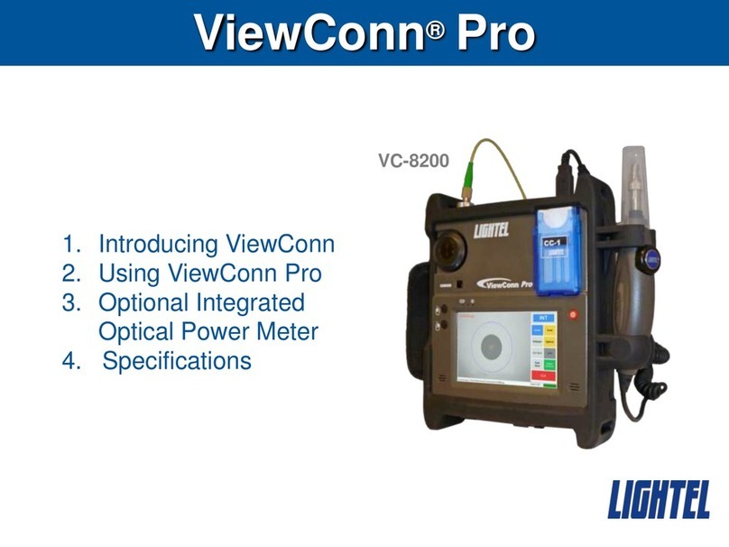
LIGHTEL Technologies ViewConn Pro User manual

2
Specifications
ViewConn
Field of View
~464μm x 348μm
Resolution
0.5 μm detectable
Optical Sensor
CMOS
Light Source
Blue LED
LCD Display
5” LCD color touchscreen
Power Supply
Li-Ion internally rechargeable battery or
12V DC adapter
Adjustable automatic power saving
Low battery indicator
Battery
Li-Ion, 7.4V, 3700mAh
Battery Life
≥3 hours (continuous)
Electrical Ports
DC adapter plug port
1 USB2.0 port
Dimensions (including
ruggedized cover)
186mm (H) x 218mm (W) x 44mm (D)
Weight (including battery
and ruggedized cover)
1.4kg
Storage
8GB SSD
Memory
1GB
Processor
Atom Z530
Internet Connection
Wi-Fi
Probe
Field of View
~660μm x 495μm
Resolution
0.5 μm detectable
Optical Sensor
CMOS
Light Source
Blue LED
Power Supply
USB2.0 connection with ViewConn
Output
USB2.0 plug
Dimensions
35mm ø x 175mm (without cap)
Software (pre-loaded)
Operating System
Windows XP®
ConnectorViewTM Plus
Pass/Fail Analysis
Full screen, touchscreen operation
Analysis Time
~4 seconds (average)
Table of Contents

3
1. Male connector tip (INT)
2. Focus knob (INT)
3. Cursor control
4. Left click (mouse) button
5. Right click (mouse) button
6. Power button
7. Probe focus knob (EXT)
8. CC-1 cleaning cassette
9. USB2.0 port
10.Optional optical power meter
14
13
13. AC power input
14. Fold-out stand
Hardware
Parts Identification
11
12
11.Battery charging light
12.Wi-Fi indicator light
13.Power indicator light
11
11. Battery charging light
12. Power indicator light
5
4
Table of Contents
1
2
3
4
5
6
7
10
9
8

4
Turning on ViewConn Pro
Press and hold for 2 seconds the red power button to turn on
ViewConn Pro.
The blue light on the right (the power indicator light) will be
continuously on when the unit is turned on and active.
When the “Lightel” screen appears touch [Start] to open the
ConnectorView Pro software.
ViewConn Pro is powered by its internal Li-ion battery or by the
included AC charger/adapter. Whenever the AC charger/adapter
is in use, the battery will automatically begin to recharge.
The red light on the left (the battery indicator light) will be on whenever the battery is charging or ViewConn
Pro is running on AC power. It will turn off if the battery is fully charged and shut off even when the unit is
plugged in. When the red and blue lights are both on, the unit is turned on, running on AC power and
recharging.
Power saving (Standby)
By default, when using battery power ViewConn Pro will go into
Standby after 5 minutes. When using AC power ViewConn Pro
will remain on until manually shut down or manually put into
Standby.
Power saving settings can be accessed through the Power
Saving button on the Tools Screen. Use the drop-down menu to
change the Standby setting.
When using battery power, it is recommended that you allow ViewConn Pro to go into Standby when
temporarily not in use. There may be no need to shut off ViewConn Pro during a workday. Standby will
save significant battery power and still enable a very rapid restart.
When there is less than one minute left before ViewConn Pro
goes into standby, the time display will turn red and the remaining
seconds will be counted down.
To manually place in ViewConn Pro in Standby touch the red
[Exit] button on the Main Screen, then the yellow [Standby] button
on the Closing Screen.
When in Standby, the left blue light will blink continuously. ViewConn Pro can be recharged while in
Standby.
To restart from Standby press and hold the red power button for two seconds.
Table of Contents

5
Inspecting Connectors
Male Connectors
When ViewConn Pro is turned on, the internal camera turns
on and the touchscreen displays the image from the
ViewConn tip (INT). This tip is used for inspecting male
connectors (patchcords and jumpers).
Once you have the proper tip in place for the connector type,
place the connector into the tip. Use the large black knob to
focus the image. If you are unable to focus the image, verify
that the tip is fully screwed in and the connector is properly
seated in the tip.
When inspecting APC type connectors (green color connector), make sure to use an APC adapter tip.
ViewConn APC tips have a brass center to easily distinguish them from PC tips.
The key on the APC connector should be aligned so that it faces the front of ViewConn. Check the display
to verify the connector is properly aligned.
Improper alignment of an APC connector on the adapting tip will cause the image to be extremely dark or
have shadows.
Changing ViewConn Tips
All ViewConn tips are intended for use
strictly with male connectors. Most
ViewConn tips are universal tips, either PC
or APC, for all connectors with the same
ferrule size.
To install a ViewConn tip, align the tip’s key
with the slot in the tip receptacle and seat it.
Once seated screw the tip in clockwise until
tight.
Key
Slot
Table of Contents
To remove a ViewConn tip, unscrew it
counterwise and lift out.

6
Cleaning Male Connectors
Once you have inspected the fiber, if you need to clean it, open
the cover of the CC-1 cleaning cassette, and, using moderate
pressure swipe the connector ferrule from the top down on a
clean section of the CC-1 cassette. Do not scrub the connector
back and forth and do not reuse a section of cleaner. Reinsert
the connector in the tip to verify that it is now clean.
Changing Cleaning Sheets
When you have used all three slots on a CC-1 cleaning sheet, pull the
sheet out to advance it to the next sheet. The cassette cover must be
open to advance the sheet. If you wish to
tear off a sheet or sheets, first close
the cover. (A quick twisting motion
works best to tear off the sheets.)
CC-1 Cleaning Cassette
To install the CC-1 cleaning cassette, place the tab at the to of the CC-1 in
the slot at the top of the cassette holder. Then push the cassette in the
space until it clicks into place.
If you wish to remove the cassette, push up on the small blue plastic tab at
the base of the cassette and lift the cassette out.
Table of Contents

7
Female Connectors
The digital probe is used to inspect female connectors (in-
adapter connectors –patch panels and bulkheads).
To inspect connectors using the probe, touch the INT portion of
the touchscreen. The view will shift to EXT and connectors can
now be inspected with the probe. The probe uses a wide-view
setting to allow the connector to be more easily located.
With the correct tip installed for the connector type, place the tip of the probe into the adapter and use the
focus knob on the probe to focus the image. If you are unable to focus, you may not have the probe tip
fully inserted. Make sure it seats fully, and refocus.
When inspecting APC type connectors (green color connector), make sure to use an APC adapter tip.
There is a mark on each tip that should match up to the key in the adapter, for proper alignment.
Touching the EXT portion of the touchscreen, will return the screen view to the internal ViewConn camera.
Changing Probe Tips
Most probe tips are for female connectors. (Universal male tips are available for the probe for special
applications.) Female tips are specific to the type of connector being inspected.
Probe tips are available in a variety of styles for specialty applications including 60° angled tips and
extended tips.
Probe tips are held in place with a locknut.
Holding the probe, turn the lock nut counter-
clockwise to loosen it fully, and then remove the tip.
All tips have a slot and fit into the key at the top of the
probe. Slide the new tip in place and slip the lock nut
over the tip. Tighten the nut snugly –if the tip is loose,
it may not focus properly.
Table of Contents

8
Software
Most buttons on the touchscreen are color coded.
Blue –Choice is active
Gray –Choice is not active
Gold –Opens or switches to a new window
Primary Screens
Main Screen
The Main Screen has all the controls you need to view, analyze and save connector images and test
results.
INT/EXT –Shifts the view between ViewConn (male connectors)
and the probe (female connectors). If the probe is not attached,
only the INT will be active. If you attach or detach the probe while
in use, you must restart the software to activate the change. (It is
not necessary to restart ViewConn, only restart the software.)
Zones –Activates the cleaning zone/ rings feature when a
connector image is frozen.
Tools –Switches screen to the Tools screen.
Analysis –Activates the Pass/Fail analysis feature. (This choice
automatically activates [Zones] button.
Options –Switches screen to the Options screen.
Hot Spot –Only for use with the EXT setting (probe). If software
is having difficulty locating the connector, activate this control and
touch the screen where the connector is located. The software
will focus on this region. It is suggested that you deactivate this
button when not needed, or inadvertant screen touches may
misdirect the software.
OPM –Switches to power meter mode. (Disabled unless a VC8-
OPM or VC8-OPM-H is installed.)
Auto-Save –Automatically captures and saves each time an
image is frozen. If Analysis button is active, it will save the
Analysis Report.
Capture and Save –Saves the connector image based on
whatever is showing on the screen at that time. Touch the image
portion of the screen to return to live video.
Exit / Standby–Exits ConnectorView Plus software to screen
with 4 buttons:
oShut Down –Shuts off ViewConn Pro.
oStandby –Places ViewConn Pro in Standby
mode.
oRestart –Restarts ConnectorView Plus
software. (Does not restart ViewConn Pro.)
oCancel –Returns to the Main Screen without
restarting the software.
Table of Contents

9
Clock –Displays the current time.
When less than one minute remains
before Standby, the numbers will
turn red and the seconds remaining
will be displayed.
Battery Indicator –Displays the percentage of the charge
remaining.
Focus Bar –Helps provide a guide for focusing when viewing the
image onscreen is difficult. The more green shown the better the focus.
Poorly focused images cannot be analyzed.
Video window –The left side of the screen displays
the connector. Touching this portion of the screen
will freeze the image and initiate the settings you
have selected. Touching this portion again returns
screen to live video.
Table of Contents
Focus Bar

10
Options Screen
The Options Screen is where you enter the
settings you wish to use for your saved
images and reports. It is also where you set
the type of fiber (single mode, multimode or
ribbon) you will be inspecting. When you
touch a textbox, the on-screen keyboard will
open. You can use the stylus located on the
underside of ViewConn Pro to type in
information in the box.
Image Filename –This will be the name assigned to your image captures and Analysis Reports.
Filename Prefix –You can type in a name of any length using any combination of letters,
numbers and symbols for your filename prefix.
File Number –The default starting number is 0001. You can type in a different 4-digit number
if you wish. Files will automatically be numbered sequentially from the starting number.
Summary Report –The information from the Analysis Report is listed in the Summary Report. You
can name the report. If you do not enter a name, the date/time is used for the report name whenever a
new report is started. Reports are in a Text file by default. If Excel is available on your unit, you can
select the Excel format for your Summary Reports.
Image File and Summary Report Location –A “ConnectorView” folder is created in the My
Documents folder as the default location for your files. You can choose a different location by touching
the […] button and sellecting a different existing folder. Also opens the onscreen keyboard.
To create and name new folders see
Image File Format –BPM, JPG, and PNG are the available image formats. Only one can be selected
at a time. The default format is JPG, which creates the smallest size files.
Fiber Type –SM (single mode), MM (multimode), and MTP/MPO are the three available fiber types.
Only one can be selected at a time. The default type is SM.
On Screen Keyboard –Manually opens the keyboard. If
the keyboard is covering a section of the screen where
you need to enter information, use the Keyboard titlebar
to drag it to a new position.
Explore –Opens the folder where you are currently
storing your images and reports. Also opens the On
Screen Keyboard. For additional details see the Appendix
Creating New Folders.
OK –Returns you to the main screen and applies any
changes you have made.
Cancel –Returns you to the main screen without applying any changes.
Table of Contents

11
Tools Screen
The Tools Screen contains buttons to open
windows which will less frequently need to be
accessed.
Manual Zone Adj –Opens window to allow you to manual identify
the ferrule if ConnectorView Plus cannot correctly locate it. For
additional details see the Appendix Manual Zone Adj.
Digital Zoom –Opens window to allow you to digitally enlarge
and center the image. Select the zoom size desired and select that
button. The arrows con be used to center the image. You cannot
save or analyze a zoomed image.
Acceptance Criteria –Opens window to allow you to change the
quantities of scratches or defects which cause a “Fail” rating. The
changes will be displayed on any new Analysis Reports.
ConnectorView Plus uses IEC 61300-3-35 as the default standard.
For additional details see the Appendix Acceptance Criteria.
Open Test Summary –Opens window to display the Summary
Report.
Image Explore –Opens the Image Explore window, so you can
view any image in your current image storage folder.
[File List] opens and closes the image list for the folder selected.
[Delete] permanently deletes the image.
[Image Folder] displays the existing folders, so you can explore
additional storage folders if you wish
To close Image Explore, touch the image portion of the screen.
Table of Contents

12
Check for Updates –If you are currently connected to the
Internet, you can check for ConnectorView Plus updates. If
there is a newer version, you will be asked if you want to
install the update.
When you click [Yes] the update will
download and install automatically. ConnectorView Plus
will then restart.
Wi-Fi –Opens the Network Connections window so you can
create a Wi-Fi connection. For additional details see the Appendix
Wi-Fi.
Power Saving –Opens the Power Saving
window so you can set the automatic Standby
time using the drop down menu.
User Manual –Opens a pdf version of this User’s Manual.
About –Opens a window showing the ConnectorView Plus
version information.
Tools Exit –Closes the Tools screen and returns you to the Main Screen.
Table of ContentsTable of Contents

13
Viewing and Saving Images and Analysis Reports
Once you have set up ViewConn Pro, the settings will remain in place even when ViewConn Pro is shut off.
You can update your settings at any time.
Touch the [Options] button on the Main Screen
to open the Options Screen. If you do not want
to use the existing Filename, touch the
Filename prefix textbox to highlight the letters.
The on-screen keyboard will open
automatically. Type in the filename prefix you
wish to use. (You will probably want to use the
stylus found in the holder on the underside of
ViewConn Pro to do your typing.) The prefix
can be of any length and combination of letters,
symbols, and numbers. This prefix and a
sequential 4 digit number will be the name for
your stored image or analysis report.
Using the keyboard titlebar, the keyboard can
be dragged to a different position on the screen if desired.
The Report name can be changed in a similar fashion. Summary Reports continue until a new report is
started or the Analysis Criteria are changed. If you have not named the Report, the Report will be saved
using the date and time when that Report ends and a new Report starts.
Touch the […] button next to the Image File and Summary File Location textbox to change the location to a
different folder. If you expect to be using several different folders, it may be easier to plug in a USB
keyboard to do your typing. (Touching the [On Screen Keyboard] button when that keyboard is open will
close that keyboard until you exit the Options Screen.)
Select the correct fiber type you will be inspecting.
Then touch [OK] to return to the Main Screen.
Select [INT] –ViewConn or [EXT] –probe. If the “INT” letters are black, the probe is
not properly connected and only [INT] will be available. With the exception of [Hot
Spot] (active only in [EXT]), selecting settings in either [INT] or [EXT] changes the
settings for both.
Determine if you want to view frozen images only –[Zones] and [Analysis] gray (off),
Zones only –[Zones] blue and [Analysis] gray or Analysis –[Zones] and [Analysis]
blue. Default is Analysis.
Select [Auto Save] if you wish to save every capture.
Table of Contents

14
Capturing and Saving Zones Images
If you are not using AutoSave, you can save Zones
images in this way.
Select [Zones] and touch the video portion of the
screen to freeze the image. Or using the hardware
controls on ViewConn, move the cursor into the video
portion and press the left click (mouse) button. The
screen will display a frozen image with the Zones
overlayed. The black button on the underside of the
probe, can also be used to do this in either [EXT] or
[INT] views.
Then touch the [Capture and Save] button. The
filename will be displayed in red on the screen when
the file has been saved. (The red name is not
displayed on the saved image.) Touch the screen
again to return to the live view.
When you use the Zones setting in the EXT view, the screen will initially freeze in the wide-view setting.
Touching the screen again will switch to the auto-centered view. Either of these views can be captured
using the [Capture and Save] button. Touch the screen again to return to the live view.
Images can also be captured in the same fashion without either [Zones] or [Analysis] selected.
Table of Contents

15
Using Analysis Setting
Touch the [Analysis] button to activate this feature. Button will be
blue when active. Select the [Auto Save] setting, or you can
choose to manually save individual Analysis Reports. [Auto Save]
should be gray if you want to save manually.
Once you have a connector image focused on the screen, touch
the Live video portion of the screen, or move the cursor into that
section of the screen and press the left click button. The word
“Wait” will appear briefly in red in the upper left corner of the
screen, and then the Analysis Report will be displayed on the full
screen.
If there is a red number in the upper left corner, the report has
already been saved. If there is no number, and you wish to save
to report, touch the portion of the report which says “Pass” or
“Fail”. This will save the report and a red file name should now
appear in the upper left corner. To return to the live video, touch
(or left click) on the connector image portion of the report.
Understanding the Analysis Report
ViewConn Pro uses IEC 61300-3-35 as the default standard for its analysis. (If you need to change the
criteria, go to [Tools]/ [Acceptance Criteria] to make the changes.)
The left portion of the screen is a frozen
image of the connector with scratches,
contamination, or defects highlighted.
The test zones are also indicated on the
screen.
Items highlighted in red have caused the
connector to fail inspection. Those in blue
are allowed by the inspection criteria.
Orange highlights are outside the Contact
Zone of the connector and are not tallied.
There is no standard for contamination or
defects outside the Contact Zone.
The right side of the report contains the statistical information. The test criteria used are listed and failing
result areas are highlighted in red for easy identification.
Table of Contents

16
ConnectorView Plus software uses the position of the
defects or contamination at the time of the test to give a
Pass/Fail rating.
If after cleaning, the defects remain in place and the
connector again passes, it can be assumed the items
are defects rather than loose debris, and the connector
can be used.
If a connector is extremely dirty, damaged or poorly
focused, you may see the following type screen when
attempting analysis. ViewConn Pro will not
automatically save a “Test Failed” result, even if [Auto
Save] has been selected. If you do wish to save this
result, touch the “Test Failed” portion of the screen to
manually save it.
Table of Contents

17
Appendix
Zones
ViewConn Pro software will display four fiber zones. They are:
A. Core
B. Cladding
C. Adhesive
D. Contact
These zones have been clearly defined and standardized in the industry. Some corporations may have
their own acceptance criteria for connectors. If there is no different corporate standard, Lightel suggests
using our default standard, IEC 61300-3-35, which is summarized here.
Single mode fiber requirements
Zone name
(diameter)
Scratches
Defects
A: Core
(0-9μm, 0-25μm)
None
None
B: Cladding
(25-120μm)
No limit
Any < 2μm
5 from 2 - 5μm
None > 5μm
C: Adhesive
(120-130μm)
No limit
No limit
D: Contact
(130-250μm)
No limit
None > 10μm
Note 1: For scratches, the requirement refers to width.
Note 2: No visible subsurface cracks in the core or cladding zones
Note 3: All loose particles should be removed. If defect(s) are non-removable, it should be within the
criteria above to be acceptable for use.
Note 4: There are no requirements for the area outside the contact zone since defects in this area have no
influence on performance. Cleaning loose debris beyond this region is recommended good practice.
Core
(A)
Cladding
(B)
Adhesive
(C)
Contact
(D)
Table of Contents

18
Multimode fiber requirements
Zone name
(diameter)
Scratches
Defects
A: Core
(0-65μm)
No limit ≤ 3μm
None > 3μm
4 ≤5μm
None > 5μm
B: Cladding
(65-120μm)
No limit ≤ 5μm
None > 5μm
Any < 2μm
5 from 2 - 5μm
None > 5μm
C: Adhesive
(120-130μm)
No limit
No limit
D: Contact
(130-250μm)
No limit
None ≥10μm
Note 1: For scratches, the requirement refers to width.
Note 2: No visible subsurface cracks in the core or cladding zones
Note 3: All loose particles should be removed. If defect(s) are non-removable, it should be within the
criteria above to be acceptable for use.
Note 4: There are no requirements for the area outside the contact zone since defects in this area have no
influence on performance. Cleaning loose debris beyond this region is recommended good practice.
Core
(A)
Cladding
(B)
Adhesive
(C)
Contact
(D)
Table of Contents

19
Tools Screens
Detailed instructions on selected Tools
screens.
Manual Zone Adj
If ConnectorView Plus is unable to correctly locate the ferrule or the rings are sized incorrectly, you can
manually position the target. Touch the screen and drag the red target over the ferrule. Then touch the red
arrows or enlarge/reduce (+/-) controls to adjust the size or make small adjustments in the target circle
position.
For INT
When the target is positioned correctly, touch the
[Zone] button. You can use the red controls to further
adjust the position if you wish.
For EXT
When the target is near the ferrule, touch [Zoom] to
enlarge the the view and complete your position
adjustments using the red controls. (Zoom must be
selected before [Zone] or [Test] become active.)
For Both
When you are satisfied with the position of the red target circle you can touch [Zone] to display Zone rings.
If you wish you can use the arrows or +/- to make additional adjustments then press [Test] to create an
Analysis Report.
Zone –Toggles the window to display the red target [Ring] and [Zone]. The caption shows what
will be displayed when the button is next touched.
Test –Creates an Analysis Report. The report will be saved if the [Auto Save] on the Main Screen
is active. Otherwise, you can save it manually by touching the “Pass” or “Fail”.
Live –Toggles the window between [Live] and [Frozen]. The caption shows what will be displayed
when the button is next touched.
Exit –Closes the Manual Zone Adj screen and returns to the Tools screen.
Table of Contents

20
Acceptance Criteria
The quantity of defects in each zone which cause a
“Fail” result can be changed. The new criteria will be
shown on the Analysis Report and the Summary
Report. (The size of the zones themselves cannot be
changed.)
To change the Acceptance Criteria from the IEC
61300-3-35 default standard, touch the [Acceptance
Criteria] button to open the window. Open the [On
Screen Keyboard] and highlight the number you wish
to change. Type in the new number. Make any
additional changes you need to make.
If you only need the new criteria, touch [Accept] to complete your changes and [Exit] to the return to the
When you next run create an Analysis Report, you will see a message stating that a new Summary Report
has be created with the new criteria and that the previous Summary Report has be saved with the date and
time for the file name. A new Summary Report is created every time the criteria are changed.
If you will be using different sets of criteria at different
times you can save new settings for later use. Once
you have changed the settings, before clicking
[Accept], go to “File/Save as…” in the Acceptance
Criteria window. Using the On Screen Keyboard type
in a name for each different criteria set. You can save
multiple sets of criteria in this manner.
To load one of your saved criteria sets go to “File/Load
from…” in the “Acceptance Criteria” window. Select
the criteria you wish to use and press [Open].The
touch [Apply] and [Exit]
The [Default] button returns the the settings to the
IEC 61300-3-35.
Table of ContentsTable of Contents
This manual suits for next models
1
Table of contents
Other LIGHTEL Technologies Analytical Instrument manuals