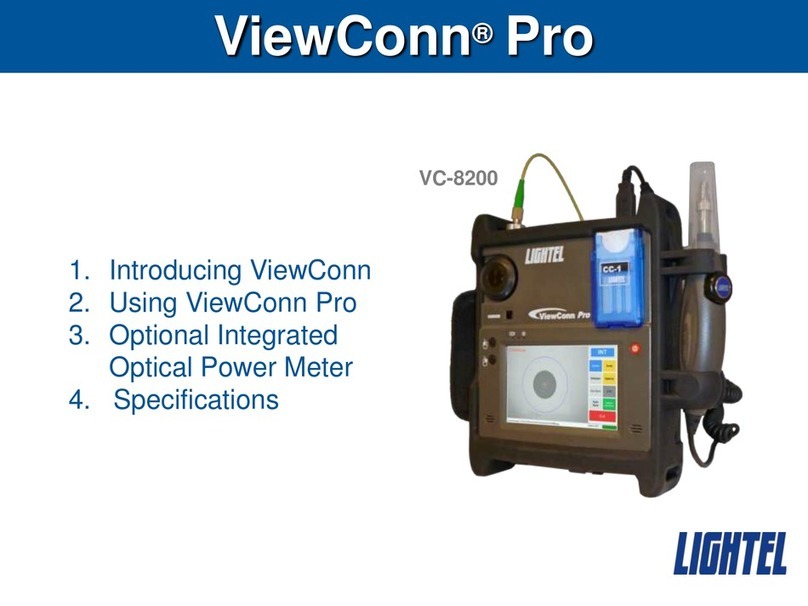
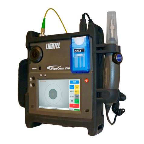
LIGHTEL Technologies VC-6200 User manual

The VC-6200 package includes the VC-6200 unit, 2 universal tips, 6V
AC adapter, battery charger with 4 AA rechargeable batteries, USB mini-
B cable and ConnectorView software, and 2 cleaning cassettes.
The VC-6200-PL adds the CI-1100 probe and tips for PC type SC, FC
and LC female (in-adapter) connectors
Specifications
ViewConn (VC-6200)
Field of View
~ 425µm x 320µm
Resolution
0.5µm detectable
Focus
Manual adjustment, 2mm max travel
Light source
Blue LED
Display
3.5” TFT-LCD, 960 x 240 pixels
Controls
Adjustable brightness and contrast
Power supply
4 AA rechargeable batteries or AC power supply
Battery life
4 hours
Charger & AC adapter
US, EU, UK and Australian versions available
Dimensions
170mm x 95mm x 30mm (without cover)
Weight
350g (without battery)
Probe (CI-1100HS)
Field of View
~ 425µm x 320µm
Resolution
0.5µm detectable
Focus
Manual adjustment, 2mm max travel
Light source
Blue LED
Power supply
ViewConn via 4-pin jack
Dimensions
35mm diameter x 175mm length (without tip)
Weight
200g
Operating Temperature
0°C to 50°C
Storage Temperature
-20°C to 70°C
2210 Lind Ave, SW, Suite 100
Renton, WA 98057, USA
(Phone) (425) 277-8000
(Fax) (425) 277-5280
E-mail: sales@lighteltech.com
Website: www.lightel.com
VC-6200 Users Manual

2
Safety
Warranty
Lightel Technologies Inc. products are shipped after passing a final inspection by
Lightel‟s Quality Assurance program. In the event of a product failure please contact
the Lightel Sales Department at (425)277-8000 or email sales@lighteltech.com
The warranty period is for one year (excluding batteries) after the date of delivery.
Should failure occur within that period, repair or replacement will be made, as
necessary, free of charge. The Warranty will not be honored if:
1. Failure is caused by usage non-conforming to the instruction manual or
negligent operation.
2. Failure is caused by an unauthorized electric or mechanical modification by the
customer.
The extent of the warranty shall be limited to repair or replacement of the defective unit.
All Lightel microscopes are eye-safe video
microscopes. Nevertheless, all standard
safety precautions should be followed.
Cleaning Cassette
ViewConn
Adapter Tip
ViewConn Focus Knob
Ruggedized Cover
Contrast Button
Brightness Control
On/Off Button
DC Power Port
Accessory Holder
Fiber Optic Connector
Camera switch (Internal/External)
Power Indicator Light
Display
4-pin DIN Socket
(not visible)
USB mini-B Socket
(not visible)

3
Power Indicator/Battery Status
On/Off
Camera Portal
Switch
Contrast
Brightness
Powering ViewConn
ViewConn may be powered by either plugging in the provided 6V DC
adapter to DC power port, or by using 4 standard AA batteries. It is
strongly recommended that high performance rechargeable AA
batteries (such as those provided) be used when using batteries.*
The Power indicator will be green when there is sufficient power.
To turn unit on, depress and hold down red On/Off button for
approximately 3 seconds, or until the screen lights up. Unit may be
turned off in a similar manner.
The VC-6200 has a power saving feature that automatically places the
unit in Stand-by mode after 5 minutes when using the batteries. When
the DC adapter is in use, Stand-by initiates after 20 minutes. To restart,
simply touch the On/Off button.
If your green power light is on, but the screen is black, briefly touch the
red on/off button. The unit may have gone into the power saving,
standby mode. Also check to ensure that the camera switch is set to INT.
Note: The DC adapter will not charge ViewConn’s batteries. A separate battery charger
has been provided, or another commercial AA battery charger can be used.
*Standard AA batteries (Alkaline) will temporarily power ViewConn, but will
typically last less than one hour. They should not be left in ViewConn, to avoid
any risk of battery leakage.

4
Inspecting Male Connectors
To inspect male connectors (patchcords and
jumpers) set the camera switch, above the red
on/off button to INT.
Ensure that you have the proper tip in the tip
receptacle at the top of ViewConn, then place the
connector into the tip.
Use the large black knob to focus the
image. If you are unable to focus the
image, verify that the tip is fully screwed
in and the connector is properly seated
in the tip.

5
Inspecting Male APC Connectors
When inspecting APC type connectors (green
color connector), make sure to use an APC
adapter tip. ViewConn APC tips have a brass
center to easily distinguish them from PC tips.
The key on the APC connector should be
aligned so that it faces the front of ViewConn.
Check the display to verify the connector is
properly aligned.
Improper alignment of an APC
connector on the adapting tip
will cause the image to be
extremely dark or have
shadows.
The same connector is now
properly aligned.

6
Cleaning Male Connectors
Once you have inspected the fiber, if you need to
clean it, open the cover of the CC-1 cleaning
cassette, and, using moderate pressure swipe the
connector ferrule from the top down on a clean
section of the CC-1 cassette. Do not scrub the
connector back and forth and do not reuse a section
of cleaner. Reinsert the connector in the tip to verify
that it is now clean.
To avoid cross-contamination, make sure that the mated
connector is also clean, before installing or reinstalling.
If the connector was not clean, repeat the procedure and again recheck.

7
Wet Cleaning
If you decide you need to wet clean a connector, use a solvent dispenser
like the optional Chemtronics Electro-Wash® pen dispenser to lightly
wet a clean section of a CC-1 sheet. Less solvent is best.
Always go from the wet portion to the clean dry portion. You always want
to finish in a dry section of the sheet to be sure the solvent has been
removed.
Reinspect your connector as before to verify it is clean.

8
CC-1 Cleaning Cassette
If you wish to remove the cassette, push up on
the small blue plastic tab at the base of the
cassette and lift the cassette out. When replacing
the cassette, make sure the tab is over the edge
of the cassette receptacle. This ensures that the
cassette will remain in place.
Changing Cleaning Sheets
When you have used all three
slots on a CC-1 cleaning sheet,
pull the sheet out to advance it to
the next sheet. The cassette
cover must be open to advance
the sheet. If you wish to tear off a
sheet or sheets,
first close the cover.
(A quick twisting
motion works best to
tear off the sheets.)
It is important to make
sure you have pushed the
CC-1 securely into place
to prevent it from falling
out unexpectedly.

9
Changing ViewConn Tips
To install a VC-6200
tip align the tip key
with the slot in the Tip
Receptacle and seat it.
Once seated, screw the tip in
clockwise until tight.
To remove, simply unscrew it
counterclockwise, and lift out.
All ViewConn tips are
intended for use strictly with
male connectors.

10
Changing Batteries
When batteries are in use the Power indicator light will begin to change
from green to orange when approximately ¾ of the battery power has
been drained. You may continue to use the unit. When there is no
longer sufficient power no image will appear on the screen, even though
the screen may still be bright. If left on, ViewConn will automatically shut
off. To continue you will need a different power source –fresh batteries
or the DC adapter.
To change the batteries, slide
open battery door on the back of
the VC-6200. When changing,
always change all 4 batteries.
Remove used batteries and insert 4 fresh
ones following the diagram printed on the
unit. Slide cover back in place making
sure it latches on both sides.
Remember to use camera grade rechargeable batteries except in an
emergency.

11
Capturing Images
ViewConn‟s USB2.0 port enables
you to connect to a Windowsbased
computer. It includes all necessary
software allowing you not only to
view, but also easily save the images
on the computer. (See the
„ConnectorViewTM Installation &
User‟s Manual‟for first time driver
and image capture software
installation and complete usage
details.)
This manual can be found on the CD
which came with ViewConn, or
downloaded from the Lightel
website.)
ConnectorView will automatically
sequentially number your image
captures with whatever filename you
create. Images are captured as bmp,
png, or jpg files and stored on your
PC. If you wish, it will automatically
show you the cleaning zones.
ViewConn can also work with
Lightel‟s optional ConnectorView
Plus software which will automatic-
ally analyze the connector endface
condition and provide a Pass/Fail
evaluation and report.

12
ViewConn Plus Probe
Inspecting Female Connectors
To inspect female connectors (in
bulkheads and patch panels) plug the 4-
pin jack on your probe into the socket on
the side of ViewConn –the flat side of
the jack will face the rear –and set the
camera switch, above the red
on/off button to EXT.
With the correct tip installed for the
connector type, place the tip of the
probe into the adapter and use the
focus knob on the probe to focus the
image. If you are unable to focus,
you may not have the probe tip fully
inserted. Make sure it seats fully,
and refocus.
Using the INT/EXT camera switch it
is simple to move back and forth
between views of the male and
female connectors.
Remember when using the probe,
focus with the probe focus knob.

13
Probe Tips
Different types of female connectors will usually require a tip designed
specifically for that connector type. PC and APC versions will be different,
and APC tips will have a mark to match the APC connector‟s key.
If you own a CI-1000 or VC-6100-PL
CI-1000 tips (Series 1 tips) and VC-6200-PL probe
tips (Series 2 tips) are clearly distinct. Series 1 tips
have an inside thread. Series 2 tips have a key slot
and are threaded on the outside.
Series 2 tips can only be used with the Series 2
probes (VC-6200-PL, CI-1100 and DI-1000). They
are not compatible with the Series 1 probe (VC-
6100-PL and CI-1000). All CI-1100 tips
start with the part number “PT2-”
In addition to standard tips Lightel offers a wide
variety of specialty tips to accommodate special
situations. Contact Lightel or your Lightel
distributor for additional information.
Angled tips
Ribbon fiber tips
Extended tips
CI-1000 tip
(Series 1)
CI-1000-LC/F
Series 2 tip
PT2-LC/PC/F
An adapter is available for Series 1 tips allowing
them to be used with the Series 2 probes (VC-
6200-PL, CI-1100 and DI-1000).
This adapter can be used with
any Series 1 tip.
PT2-CI/ADAPT

14
Changing CI-1100 tips
CI-1100 tips are held in
place by a locknut.
Holding the probe, turn the lock
nut counter-clockwise to loosen it
fully, and then remove the tip.
All tips have a slot and fit into the
key at the top of the probe. Slide
the new tip in place and slip
the lock nut over the tip. (You
may want to use a finger to
hold the tip in place until the
locknut has started
threading.) Tighten the nut
snugly –if the tip is loose, it
may not focus properly.
60° angled tips have two key slots at top and bottom to allow use
from two different directions.
The front end of the MTP/APC tip can
be set in two positions in a similar
fashion.
Locknut

15
Cleaning Female Connectors
Swabs and a number of different cleaning devices are available for
cleaning female connectors. Because it is easy to use, effective and can
be conveniently carried in the ViewConn accessory holder, many users
have adopted the IBC cleaners for use with ViewConn.
No matter what products or methods you use, make certain to reinspect
the connector before mating it. Never assume that because you have
“cleaned” the connector, the connector is clean.
To easily attach the cleaner
to ViewConn hold ViewConn
in your left hand and use
your thumb to pull the front
flap of the accessory holder
forward. Then slip the IBC
cleaner into place. It will
remain securely fastened
until you wish to remove it.

16
Accessories
Two integrated power meters –for standard and higher power –are
available for ViewConn.
The power meter plugs into ViewConn‟s 4-
pin socket (the same one used by the probe)
and is powered by ViewConn. On/Off is
controlled by ViewConn‟s power button. The
power meter can store up to 999 readings
and download them through its own USB
output. Universal 2.5mm and 1.25mm tips
are available. These tips work with both PC
and APC connectors.
To use the power meter, attach it to
ViewConn with the 4-pin jack and secure it to
the ViewConn accessory holder. With ViewConn turned on, set the
camera switch to EXT.
Lightel offers two types of ViewConn cases, neck straps, tip boxes and a
variety of cleaning products.
VC6-OPM
Other LIGHTEL Technologies Analytical Instrument manuals