Page 2 of 6
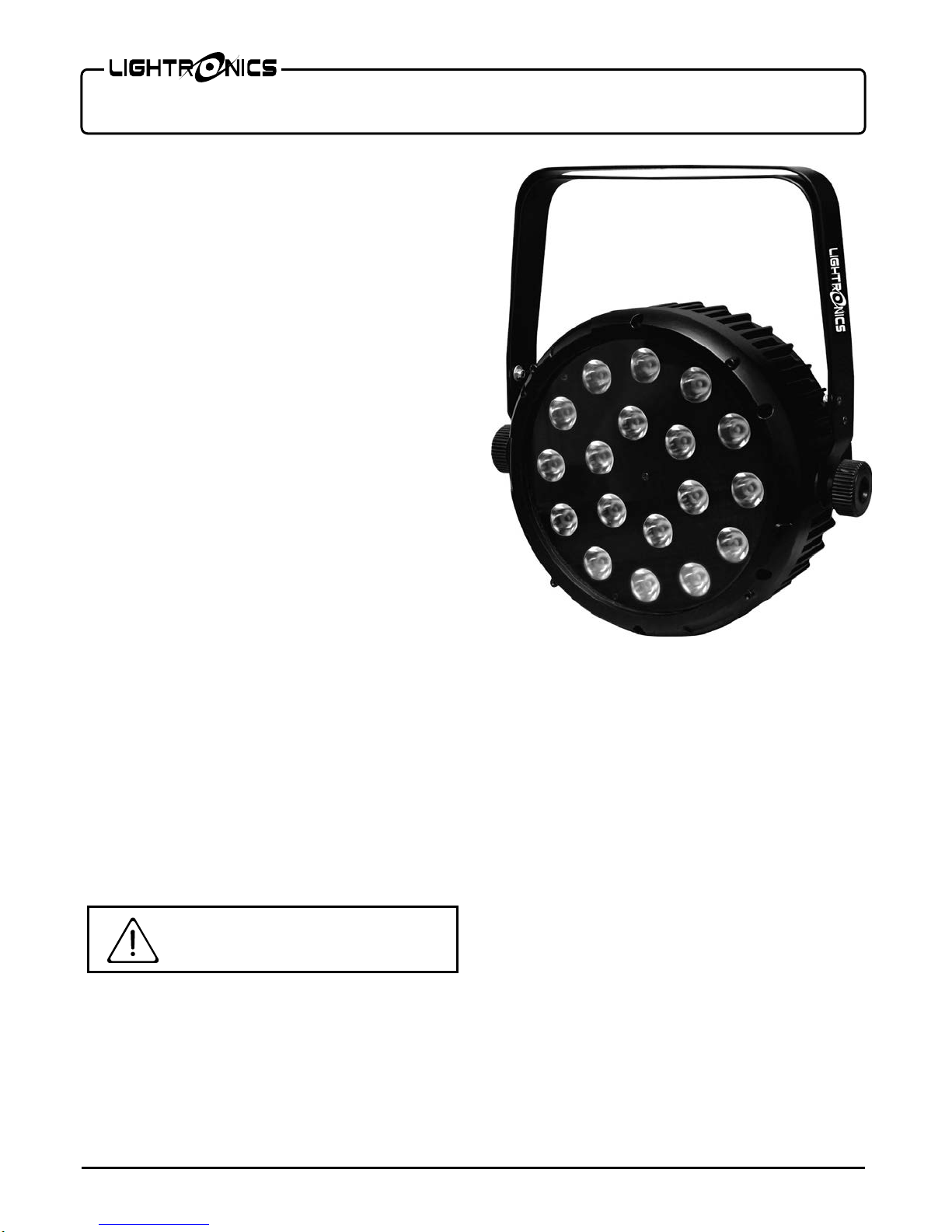
FXLD1218FRP5I LED FIXTURE
Version 0.1 OWNERS MANUAL 08/01/2016
www.lightronics.com
Lightronics Inc. 509 Central Drive Virginia Beach, VA 23454 757 486 3588
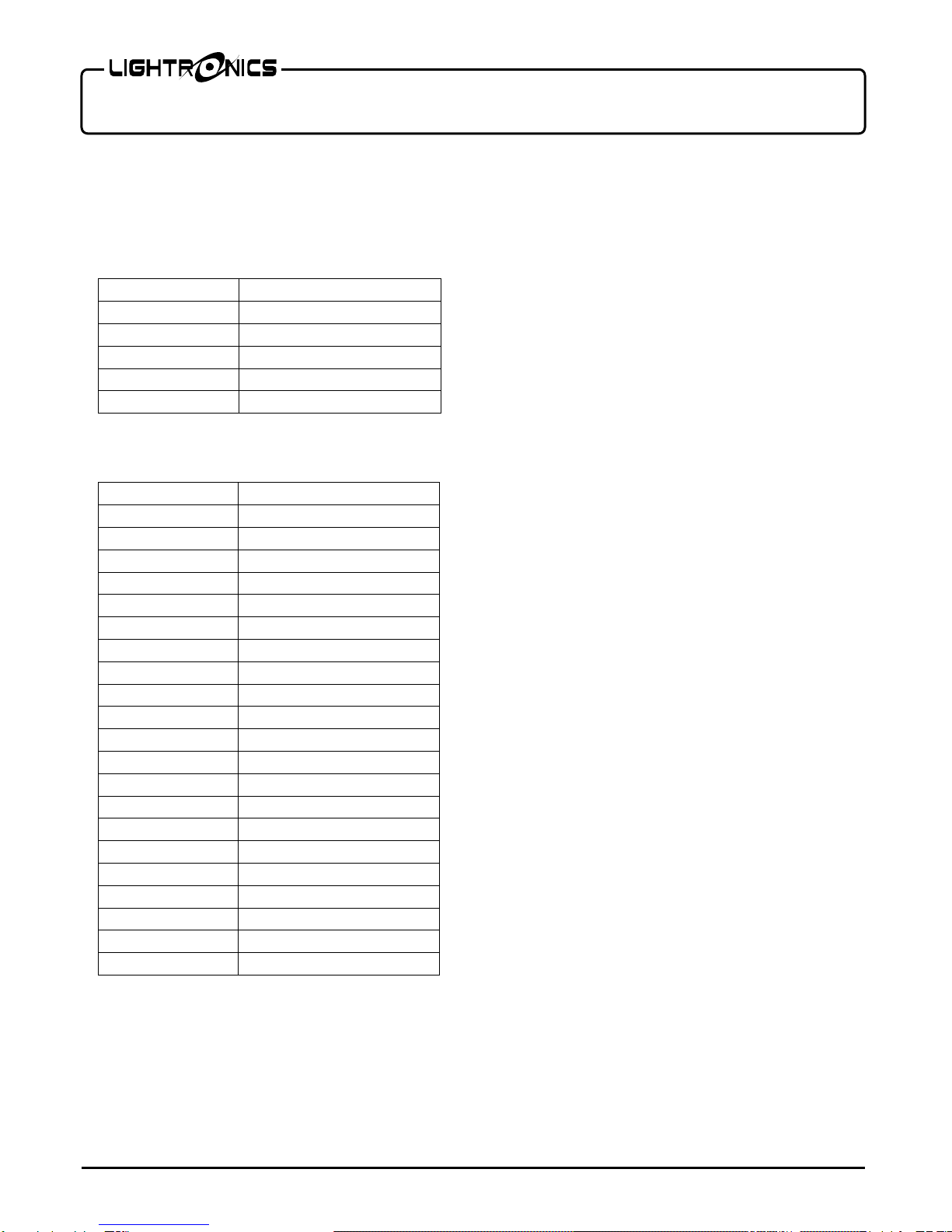
DMX CONNECTOR PIN ASSIGNMENTS
There are two different connectors generally used for
DMX control. They are both XLR type connectors.
Some units use 3 pin connectors. Others use 5 pin. The
FXLD1218FRP5I has both. DMX can be received on
either the 3 pin or 5 pin MALE connector on the back
of the unit. The 3 and 5 pin FEMALE connectors are
used to connect to the next DMX device on the control
chain.
The table below shows the pin assignments for BOTH
the 3 pin and 5 pin connectors.
DMX TERMINATION
A DMX chain should be terminated at the last
receiving device on the chain. This is done by
installing a commonly available 1/4 Watt, 120 Ohm
resistor across the DATA - and DATA + wires at the
last device. If you have only a few fixtures very close
together and a very short run to the controller then you
may be able to operate without the terminator.
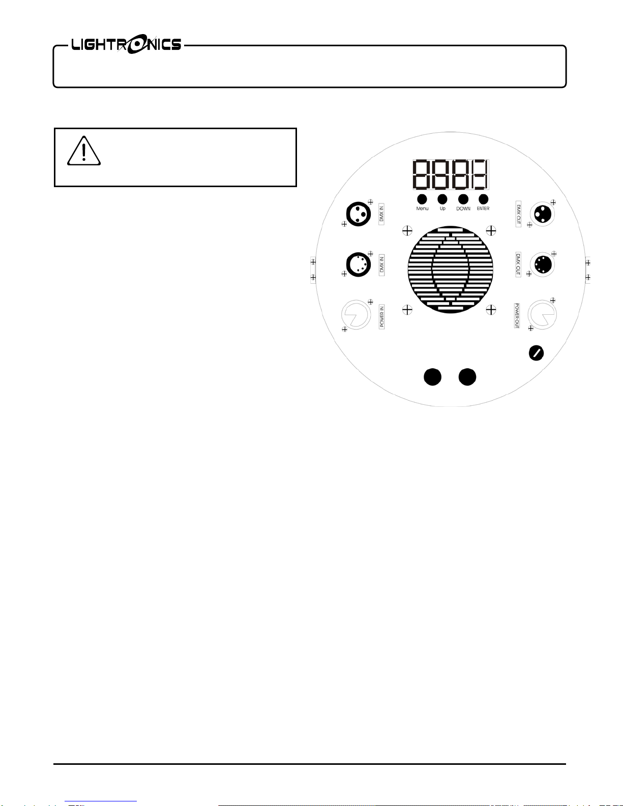
OPERATION
A control panel on the back of the unit is used to set
the operating options. It consists of an LED display
and four buttons (MENU, UP, DOWN, and ENTER)
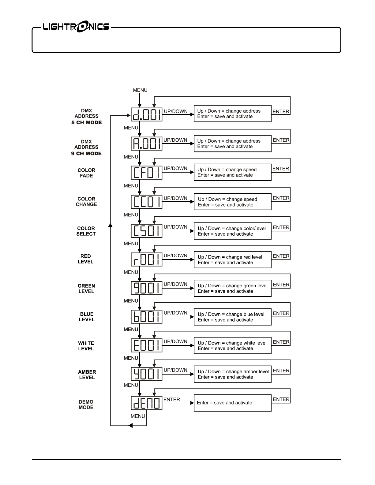
Push MENU to access the operating options. When
you reach the option you want to set or change - use
UP or DOWN to set a value. Push ENTER to save your
changes and activate the option. See the "MENU
NAVIGATION" diagram for additional details.
There are 7 operation modes: DMX 5 channel, DMX 9
channel, Color Fade, Color Change, Color Select,
Manual Level (5 selections), and Demo.
DMX OPERATION
For DMX operation the FXLD1218FRP5I fixture can
be configured as a 5 channel, or 9 channel unit.
Use the
(5 ch) or
(9 ch) menu to set the
starting address of the unit. You can select the starting
address of the unit with the UP and DOWN buttons.
Detailed information on DMX channel operation is
given in the tables DMX VALUES AND FUNCTIONS.
MANUAL OPERATION
Color Select (
)
For additional manual operations you can use the Color
Select menu (
) to select a color and level.
Color Change
The color change mode cycles through a variety of
colors at a user defined speed. Use the
menu to
set the rate of speed at which the colors change. The
range is from 01 to 99. 99 is fastest and 01 is the
slowest.
COLOR FADE (
)
The Color Fade mode cycles smoothly through a
sequence of colors. Use the
menu to set the
speed and activate the option. The range is from 1 to
99. 99 is fastest.
R, G, B, W, A MANUAL LEVEL CONTROL
You can operate the individual color levels manually
using the
r000, g000, b000, E000, and Y000
menus. Use the UP and DOWN buttons to change the
level, Push ENTER when done. The range is 000 -
255 (255 is maximum).
DEMO MODE (
)
This option is currently not operable with this unit.