Lightronics FXLD618FRP2I4 User manual

Page 1 of 6
FXLD618FRP2I4 LED FIXTURE
Version 0.2 OWNERS MANUAL 10/04/17
www.lightronics.com
Lightronics Inc. 509 Central Drive Virginia Beach, VA 234354 757 486 3588
FEATURES AND SPECIFICATIONS
LEDS: 18, 6W each (Warm White, Cool White, 2in1)
Beam angle: 25º or 45°
Control system: DMX512 + Stand Alone Modes
DMX channels: 1/2/3/4/5
DMX connectors: 3 pin XLR
Voltage: 120-240 VAC 50/60Hz
Max power consumption: 120 Watts
Refresh Rate: > 3000Hz
Color Temp.: 3200K - 7000K
Cooling: Internal Fan
Body material: Die Cast Aluminum
Body color: Black
Size: 9.9"L x 9.9"W x 4.5"D (without brackets)
Weight: 10 lbs. (4.5kg)
DESCRIPTION
The FXLD618FRP2I4 is a variable white LED lighting
fixture. It is suitable for stage, disco, night club, and
other artistic applications. It has several stand-alone
control modes and can operate via a DMX512 external
signal.
A double yoke enables the fixture to be operated in
several positions.
INSTALLATION
LOCATION
The FXLD618FRP2I4 is rated IP20 and is intended for
INDOOR USE ONLY.
Locate the unit in a well ventilated area away from
moisture and heat. Keep the vent holes clear. Holes
are provided on the yokes to install a lighting bar pipe
clamp. Use a safety cable when hanging the fixture.
POWER CONNECTIONS
The FXLD618FRP2I4 has a blue turn and lock
connector for power input. A compatible power cable is
provided for connection to a 120 VAC, 15 Amp, 60Hz,
grounded service. Push the blue connector on the
cable straight into the blue connector on the unit and
twist approx. 1/8 turn clockwise to latch it.
The white turn and lock connector on the unit is used
to pass power on to another FXLD618FRP2I4 unit. A
mating white connector is also provided.
Caution is advised since the line cord is rated for
approx. 7 Amps maximum.
THE SAFETY GROUND TERMINAL ON THE POWER
CABLE MUST BE USED.
DMX CONNECTIONS
A system using DMX control should be connected as a
chain of devices. In other words the control signal
cable should proceed from the controller to the first
receiving device and then to others in a continuous
"daisy chain" fashion.
The fixture has a DMX IN and a DMX OUT connector
to be used to connect the chain. The control cable
should NOT be split into a multiple run star
arrangement with a cable running from the controller
directly to each receiving device pack.
CAUTION
RISK OF ELECTRIC SHOCK

Page 2 of 6
FXLD618FRP2I4 LED FIXTURE
Version 0.2 OWNERS MANUAL 10/04/17
www.lightronics.com
Lightronics Inc. 509 Central Drive Virginia Beach, VA 234354 757 486 3588
DMX CONNECTOR PIN ASSIGNMENTS
This unit uses a 3 pin XLR type connectors. The
FXLD618FRP2I4 receives a DMX signal on the 3 pin
MALE connector on one side of the unit. The 3 pin
FEMALE connector is used to connect the next DMX
device on the control chain.
DMX TERMINATION
A DMX chain should be terminated at the last receiving
device on the chain. This is done by installing a
commonly available 1/4 Watt, 120 Ohm resistor across
the DATA - and DATA + wires at the last device. If you
have only a few fixtures very close together and a very
short run to the controller then you may be able to
operate without the terminator.
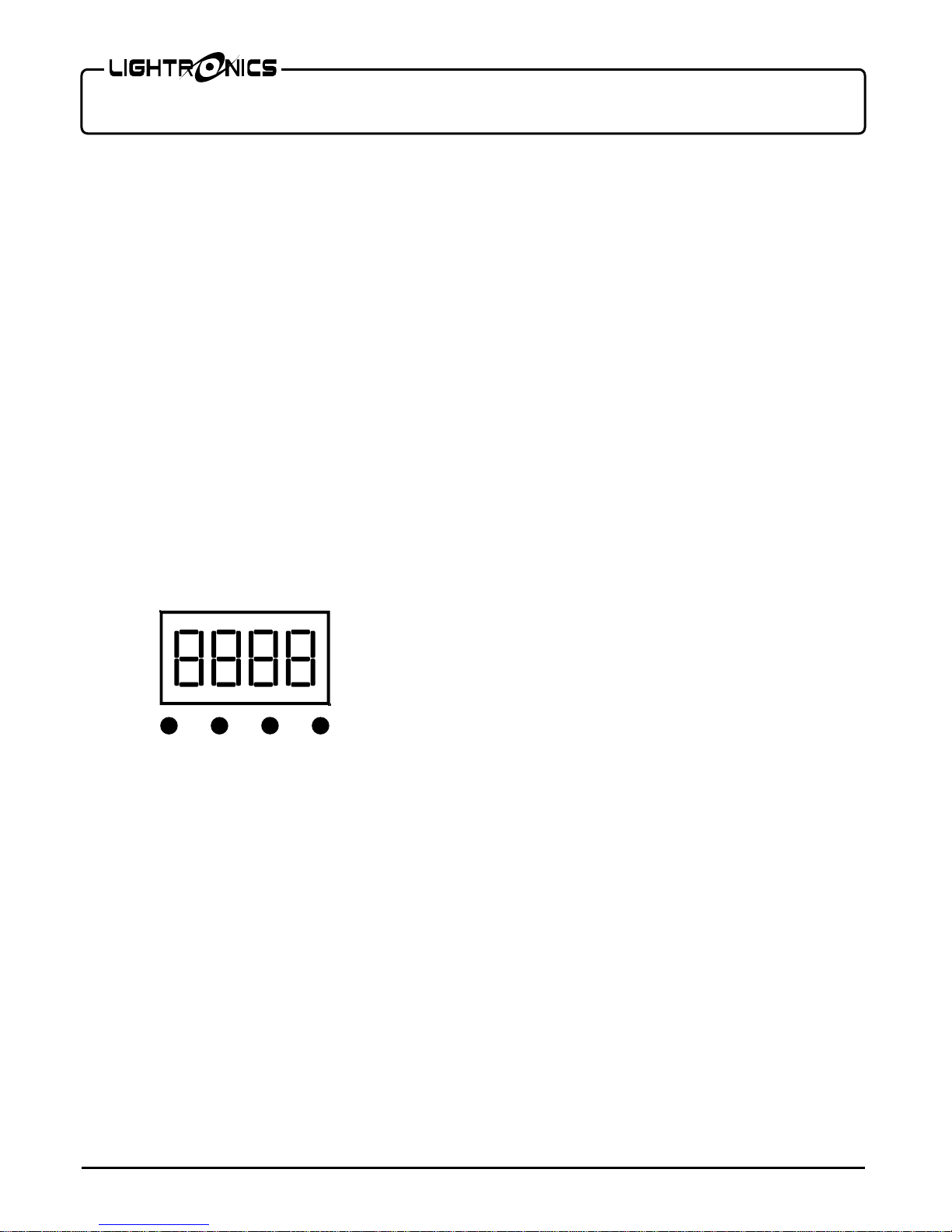
OPERATION
A control panel on one side of the unit is used to set
the operating options. It consists of an LED display
and four buttons (MENU, UP, DOWN, and ENTER)
Push MENU to access the operating options. Then use
UP and DOWN to scroll through the available choices.
When you reach the option you want to set or change -
push ENTER.Now you can view the current setting for
the option and/or change it. Push ENTER to save your
changes and activate the option. See the "MENU
NAVIGATION" diagram for additional details.
There are 9 operation modes: DMX, Color Fade, Color
Change, Color Select, Manual Level (2 selections),
Demo, Sound, delo.
The display will default to 0XXC. This is a display of
the current LED plate temperature. The fan on the unit
will only turn on when temperature is at or above 45ᵒC
DMX OPERATION
Use the Addr menu to set the starting address of the
unit. You can set the starting address of the unit with
the UP and DOWN buttons.
For DMX operation the FXLD618FRP2I4 fixture can be
configured as a 1 channel, 2 channel, 3 channel, 4
channel or 5 channel unit.
Set the CHXX menu to 01 (1 channel), 02
(2 channel), 03 (3 channel), 04 (4 channel), or 05 (5
channel).
Detailed information on DMX channel operation is
given in the tables DMX VALUES AND FUNCTIONS.
Manual Operation
If there is no DMX signal provided to the unit then
setting any of these will result in the unit that was set
acting as a master. DMX signals will override all
manual settings. The unit has a signal receive LED on
the menu display. If the unit is flashing the unit is not
receiving signal either from a DMX controller or from a
master light.
Color Select (CSXX)
For additional manual operations you can use the
Color Select menu (CSXX) to select one of three
preset color temperature settings.
Color Change (CCXX)
The color change mode cycles through 3 preset color
temperature settings at a user defined speed. Use the
CCXX menu to set the rate of speed at which the
colors change. The range is from 01 to 99. 99 is
fastest and 01 is the slowest.
COLOR FADE (CFXX)
The Color Fade mode cycles smoothly through 3
preset color temperature settings. Use the CFXX
menu to set the speed and activate the option. The
range is from 1 to 99. 99 is fastest.
Warm White/Cool White MANUAL LEVEL
CONTROL
You can operate the individual color levels manually
using the E000, and u000 menus. Use the UP and
DOWN buttons to change the level, Push ENTER
when done. The range is 000 - 255 (255 is maximum).
MENU
UP
DOWN
ENTER
CONTROL PANEL

Page 3 of 6
FXLD618FRP2I4 LED FIXTURE
Version 0.2 OWNERS MANUAL 10/04/17
www.lightronics.com
Lightronics Inc. 509 Central Drive Virginia Beach, VA 234354 757 486 3588
DEMO MODE (dENo)
The Demo mode is a stand-alone mode designed to
test the unit. The Demo mode will not work if the unit
is receiving DMX.
SOUND MODE (Soun)
The unit reacts to low end bass sounds by cycling
through 3 preset color temperatures. There are no
other settings within this mode.
Brightness on the sound mode can be set using a DMX
controller. The default for the unit is full brightness.
DIMMER CURVE MODE (dEL0)
Option not supported at this time.
MAINTENANCE AND REPAIR
TROUBLESHOOTING
Check that you have power applied to the unit.
Check the DMX control cable.
Check the address settings of the unit and the
controller.
CLEANING
Do not use harsh chemicals or solvents when cleaning
the fixture. A mild detergent can be used sparingly if
needed. Ensure that the unit is completely dry before
re-use.
REPAIR
The fixture contains a 2 Amp 250VAC, fast acting,
5mm x 20mm externally accessible fuse. Replace the
fuse ONLY with the same size and type.
The FXLD618FRP2I4 does not contain any other user
serviceable parts. Internal service on the unit by other
than Lightronics authorized agents will void the
warranty.
If service is required, contact the dealer from whom
you purchased the item, or contact the Lightronics,
Service Department, 509 Central Drive, Virginia Beach,
VA 23454. Tel: 757 486 3588.
CAUTION DO NOT OPEN UNIT
RISK OF ELECTRIC SHOCK
RISK OF FIRE

Page 4 of 6
FXLD618FRP2I4 LED FIXTURE
Version 0.2 OWNERS MANUAL 10/04/17
www.lightronics.com
Lightronics Inc. 509 Central Drive Virginia Beach, VA 234354 757 486 3588
MENU NAVIGATION

Page 5 of 6
FXLD618FRP2I4 LED FIXTURE
Version 0.2 OWNERS MANUAL 10/04/17
www.lightronics.com
Lightronics Inc. 509 Central Drive Virginia Beach, VA 234354 757 486 3588
1 CHANNEL MODE
2 CHANNEL MODE
3 CHANNEL MODE
4 CHANNEL MODE
5 CHANNEL MODE
CHANNEL NO.
FUNCTION
1
0 - 255 Master Dimmer
CHANNEL NO.
FUNCTION
1
0 - 255 Warm White
2
0 - 255 Cool White Level
CHANNEL NO.
FUNCTION
1
Master Dimmer
2
0 - 255 Warm White
3
0 - 255 Cool White Level
CHANNEL NO.
FUNCTION
1
Master Dimmer
2
Strobe Control
3
0 - 255 Warm White
4
0 - 255 Cool White Level
CHANNEL NO.
FUNCTION
1
Master Dimmer
2
Strobe Control
3
0 - 255 Warm White Level
4
0 - 255 Cool White Level
5
0 - 255 Color Temperature
DMX VALUES AND FUNCTIONS

This product is warranted for a period of TWO YEARS from the date of purchase against defects
in materials and workmanship.
This warranty is subject to the following restrictions and conditions:
A) If service is required, you may be asked to provide proof of purchase from an authorized
Lightronics dealer.
B) This warranty is valid only for the original purchaser of the unit.
C) This warranty does not apply to damage resulting from abuse, misuse, accidents, shipping,
and repairs or modifications by anyone other than an authorized Lightronics service
representative.
D) This warranty is void if the serial number is removed, altered or defaced.
E) This warranty does not cover loss or damage, direct or indirect arising from the use or
inability to use this product.
F) Lightronics reserves the right to make any changes, modifications, or updates as deemed
appropriate by Lightronics to products returned for service. Such changes may be made
without prior notification to the user and without incurring any responsibility or liability for
modifications or changes to equipment previously supplied. Lightronics is not responsible for
supplying new equipment in accordance with any earlier specifications.
G) This warranty is the only warranty either expressed, implied, or statutory, upon which the
equipment is purchased. No representatives, dealers or any of their agents are authorized to
make any warranties, guarantees, or representations other than expressly stated herein.
H) This warranty does not cover the cost of shipping products to or from Lightronics for service.
I) Lightronics Inc. reserves the right to make changes as deemed necessary to this warranty
without prior notification.
Lightronics Inc. 509 Central Drive Virginia Beach, VA 23454 20100211
WARRANTY
Table of contents
Other Lightronics Dj Equipment manuals

Lightronics
Lightronics FXLD2512B5I6 User manual

Lightronics
Lightronics FXLD1218FRP5I User manual

Lightronics
Lightronics FXLD1218FR5I User manual

Lightronics
Lightronics FXLD157FRP6I2 User manual

Lightronics
Lightronics FXLD157FRP6I2 User manual

Lightronics
Lightronics FXLD127FRP5I2 User manual

Lightronics
Lightronics FXLD618FR2I User manual

Lightronics
Lightronics FXLE17C4N User manual

Lightronics
Lightronics FXLE1260W User manual

Lightronics
Lightronics FXLD336ZM3I User manual