Lightronics FXLD618FR2I User manual

Page 1 of 4
FXLD618FR2I LED FIXTURE
Version 1.1 OWNER’S MANUAL 05/11/2022
www.lightronics.com
Lightronics Inc. 509 Central Drive, Virginia Beach, VA 23454 757 486 3588
FEATURES AND SPECIFICATIONS
LEDS: 18, 6W each (Warm White, Cool White, 2in1)
Beam angle: 45° (25º optional)
Control system: DMX-512 + Stand Alone Modes
DMX channels: 1/2/3/4/5
DMX connectors: 3 pin XLR
Voltage: 120-240 VAC 50/60Hz
Max power consumption: 120 Watts
Ingress Protection: IP20 - Indoor Use Only
Refresh Rate: > 3000Hz
Color Temp.: 3200K - 7000K
Cooling: Intelligent Fan
Body material: Die Cast Aluminum
Body color: Black (White optional)
Size: 9.9"L x 9.9"W x 4.5"D (without brackets)
Weight: 12.5 lbs. (4.5kg)
DESCRIPTION
The FXLD618FR2I is a variable white LED lighting
fixture. It is suitable for stage, house of worship,
entertainment venues, and other artistic applications.
It has several stand-alone control modes and can
operate via a DMX512 external signal.
A double yoke enables the fixture to be operated in
several positions.
INSTALLATION
LOCATION
Locate the unit indoors in a well ventilated area away
from moisture and heat. Keep the vent holes clear.
Holes are provided on the yokes to install a lighting bar
pipe clamp. Use a safety cable when hanging the
fixture.
POWER CONNECTIONS
The FXLD618FR2I has a blue turn and lock connector
for power input. A compatible power cable is provided
for connection to a 120 VAC, 15 Amp, 60Hz, grounded
service. Push the blue connector on the cable straight
into the blue connector on the unit and twist approx.
1/8 turn clockwise to latch it.
The white turn and lock connector on the unit is used
to pass power on to another FXLD618FR2I unit. A
mating white connector is also provided.
THE LINE CORD IS RATED FOR 7 AMPS MAXIMUM
THE SAFETY GROUND TERMINAL ON THE POWER
CABLE MUST BE USED.
DMX CONNECTIONS
A system using DMX control should be connected as a
chain of devices. In other words, the control signal
cable proceeds from the controller to the first receiving
device and then to others in one continuous chain.
The fixture has a DMX IN and a DMX OUT connector
to be used to connect the chain. The control cable
should NOT be split into a multiple run star
arrangement with a cable running from the controller
directly to each receiving device.
DMX CONNECTOR PIN ASSIGNMENTS
The FXLD618FR2I receives a DMX signal on the 3 pin
MALE connector on one side of the unit. The 3 pin
FEMALE connector is used to connect the next DMX
device on the control chain.
PIN #
SIGNAL NAME
1
DMX COMMON
2
DMX DATA -
3
DMX DATA +
DMX TERMINATION
A DMX chain should be terminated at the last receiving
device on the chain. This is done by installing a
commonly available 1/4 Watt, 120 Ohm resistor across
the DATA - and DATA + wires at the last device. If you
have only a few fixtures very close together and a very
short run to the controller, then you may be able to
operate without the terminator.
CAUTION
RISK OF ELECTRIC SHOCK

Page 2 of 4
FXLD618FR2I LED FIXTURE
Version 1.1 OWNER’S MANUAL 05/11/2022
www.lightronics.com
Lightronics Inc. 509 Central Drive, Virginia Beach, VA 23454 757 486 3588
OPERATION
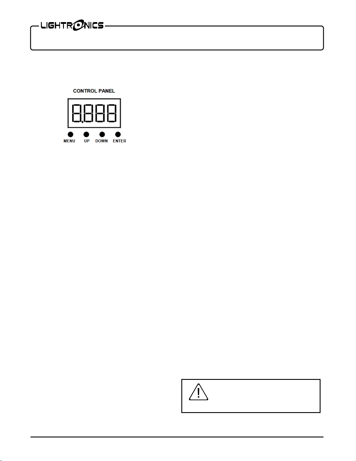
A control panel on one side of the unit is used to set
the operating options. It consists of an LED display
and four buttons (MENU, UP, DOWN, and ENTER).
.
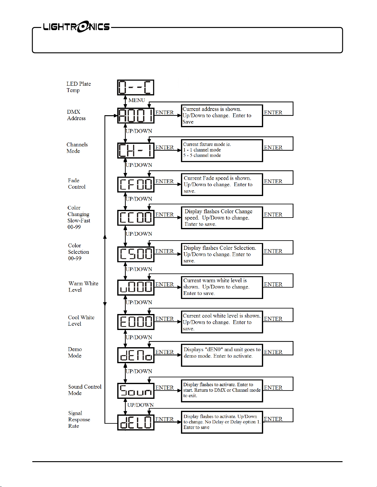
Push MENU to access the operating options. Then use
UP and DOWN to scroll through the available choices.
When you reach the option you want to set or change -
push ENTER. Now you can view the current setting for
the option and/or change it. Push ENTER to save your
changes and activate the option. See the "MENU
NAVIGATION" diagram for additional details.
There are 7 operation modes: DMX, Color Fade, Color
Change, Color Select, Manual Level (2 selections),
Demo and Sound.
The display will default to 0XXC, which is a display of
the current LED plate temperature. The fan on the unit
will only turn on when temperature is at or above 45° C
and turns off at or below 34° C.
DMX OPERATION
Use the AXXX menu to set the starting address of the
unit. You can set the starting address of the unit with
the UP and DOWN buttons.
For DMX operation the FXLD618FR2I fixture can be
configured as a 1, 2, 3, 4, or 5 channel unit.
Set the CHXX menu to 01 (1 channel), 02 (2 channel),
03 (3 channel), 04 (4 channel), or 05 (5 channel).
Detailed information on DMX channel operation is
given in the tables DMX VALUES AND FUNCTIONS.
The unit has an LED on the menu display (decimal
point). If the LED is flashing, the unit is NOT receiving
signal either from a DMX controller or from a master
fixture. LED will disappear once DMX is present.
MANUAL OPERATION
If there is no DMX signal provided to the unit, then
setting any of these will result in the unit that was set
acting as a master. DMX overrides all manual settings.
COLOR FADE (CFXX)
The Color Fade mode cycles smoothly through 3
preset color temperature settings. Use the CFXX
menu to set the speed and activate the option. The
range is from 0 to 99 with 99 as the fastest.
COLOR CHANGE (CCXX)
The color change mode cycles through 3 preset color
temperature settings at a user defined speed. Use the
CCXX menu to set the rate of speed at which the
colors change. The range is from 0 to 99 with 99 as the
fastest.
COLOR SELECT (CSXX)
For additional manual operations, you can use the
Color Select menu (CSXX) to select one of three
preset color temperature settings.
Warm White/Cool White MANUAL LEVEL
CONTROL
Individual color levels can be controlled manually using
the u000 (warm white), and E000 (cool white) menus.
Use the UP and DOWN buttons to change the level,
then push ENTER when done. The range is 000 - 255.
DEMO MODE (dENo)
The Demo mode is a stand-alone mode designed to
test the unit. The Demo mode will not work if the unit
is receiving DMX. Exit Demo mode by entering
Channel mode menu option or insert a DMX signal.
SOUND MODE (Soun)
The unit reacts to sounds by cycling through three
preset color temperatures. There are no other settings
within this mode.
Dimmer Delay (dEL0)
The operation of this function has been discontinued.
MAINTENANCE AND REPAIR
CAUTION DO NOT OPEN UNIT
RISK OF ELECTRIC SHOCK
RISK OF FIRE

Page 3 of 4
FXLD618FR2I LED FIXTURE
Version 1.1 OWNER’S MANUAL 05/11/2022
www.lightronics.com
Lightronics Inc. 509 Central Drive, Virginia Beach, VA 23454 757 486 3588
TROUBLESHOOTING
Check that you have power applied to the unit.
Check the DMX control cable.
Check the address settings of the unit and the
controller.
If no DMX signal is present, there will be a flashing
decimal point between 1st & 2nd character on display.
CLEANING
Do not use harsh chemicals or solvents when cleaning
the fixture. A mild detergent can be used sparingly if
needed. Use a cloth, do not spray or apply direct to
fixture. Ensure that the unit is completely dry before re-
use.
REPAIR
The fixture contains a 2 Amp 250VAC, fast acting,
5mm x 20mm externally accessible fuse. Replace the
fuse ONLY with the same size and type.
The FXLD618FR2I does not contain any other user
serviceable parts. Internal service on the unit by other
than Lightronics authorized agents will void the
warranty.
If service is required, contact the dealer from whom
you purchased the item, or contact the Lightronics
Service Department, 509 Central Drive, Virginia Beach,
VA 23454. Tel: 757 486 3588.
WARRANTY INFORMATION AND
REGISTRATION – CLICK LINK BELOW
www.lightronics.com/warranty.html
DMX VALUES AND FUNCTIONS
1 CHANNEL MODE
CHANNEL
VALUE
FUNCTION
1
0-255
Warm & Cool White Intensity
2 CHANNEL MODE
CHANNEL
VALUE
FUNCTION
1
0 - 255
Warm White Intensity
2
0 - 255
Cool White Intensity
3 CHANNEL MODE
CHANNEL
VALUE
FUNCTION
1
0-255
Dimmer
2
0-255
Warm White Intensity
3
0-255
Cool White Intensity
4 CHANNEL MODE
CHANNEL
FUNCTION
VALUE
DESCRIPTION
1 Master
Dimmer 0-255 0%-100%
Intensity
2 Strobe
Control
0-3 No Strobe
4-127
Slow to Fast
128-131 No Strobe
132-255 Random
3 Warm White 0-255 0%-100%
Intensity
4 Cool White 0-255 0%-100%
Intensity
5 CHANNEL MODE
CHANNEL FUNCTION VALUE DESCRIPTION
1 Master
Dimmer 0-255 0%-100%
Intensity
2 Strobe
Control
0-3 No Strobe
4-127 Slow to fast
128-131 No Strobe
132-255 Random Strobe
3 Warm White 0-255 0%-100%
Intensity
4 Cool White 0-255 0%-100%
Intensity
5 Static Preset
0-63 Off
64-127 Warm White
128-191 Cool White
192-255 Neutral White

Page 4 of 4
FXLD618FR2I LED FIXTURE
Version 1.1 OWNER’S MANUAL 05/11/2022
www.lightronics.com
Lightronics Inc. 509 Central Drive, Virginia Beach, VA 23454 757 486 3588
MENU NAVIGATION
Other Lightronics Dj Equipment manuals

Lightronics
Lightronics FXLD127FRP5I2 User manual

Lightronics
Lightronics FXLD2512B5I6 User manual

Lightronics
Lightronics FXLE17C4N User manual

Lightronics
Lightronics FXLD1218FRP5I User manual

Lightronics
Lightronics FXLD1218FR5I User manual

Lightronics
Lightronics FXLD157FRP6I2 User manual

Lightronics
Lightronics FXLD618FRP2I4 User manual

Lightronics
Lightronics FXLD157FRP6I2 User manual

Lightronics
Lightronics FXLD336ZM3I User manual

Lightronics
Lightronics FXLE1260W User manual