Page 1 of 5
FXLE17C4N LED FIXTURE
Version 0.1 OWNERS MANUAL 6/9/2017
www.lightronics.com
Lightronics Inc. 509 Central Drive, Virginia Beach, VA 23454 757 486 3588
FEATURES AND SPECIFICATIONS
LED: 170 Watt 4in1 Quad-Color, RGBW, CREE array.
White Color Temp: Adjustable 3000k-7000k
Beam Angle: 19º or 26º or 36º
Control System: DMX512 + Stand Alone
DMX Channels: 9
DMX Connectors: 3 pin XLR
Power Input: 120VAC, 60Hz
Max. Power Consumption: 200 Watts
Body Material: High Impact Plastic
Body Color: Black or White
Reflector: Glass
Gel Frame and Size "B" Gobo Holder Included
Size: 26"L x 14"W x 18"H (with yoke)
Weight: 14.2 lbs
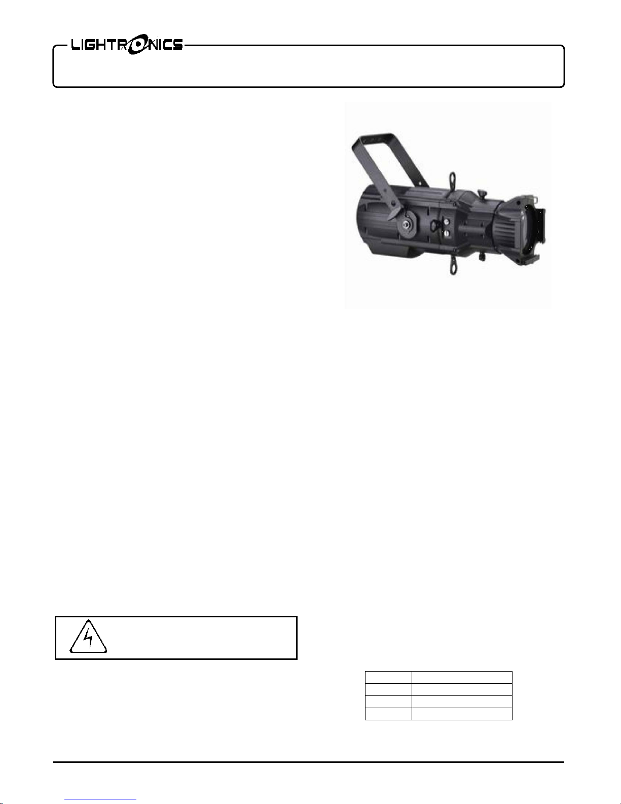
DESCRIPTION
The FXLE17C4N is a LED ellipsoidal fixture suitable
for stage, disco, night club, and other artistic
applications. It has automatic stand-alone control
modes and can operate via a DMX512 external signal.
A mounting yoke enables the fixture to be installed and
operated in various positions and orientations.
INSTALLATION
LOCATION
The FXLE17C4N is rated IP20 and is intended for
INDOOR USE ONLY.
Locate the unit in a well ventilated area away from
moisture or heat. Maintain a minimum spacing of 20"
between the unit and other objects. The maximum
ambient operating temperature is 45ºC (113ºF). Keep
the vent holes clear. Holes are provided on the yokes
to install a traditional lighting c-clamp for mounting on
batten pipe. Use a safety cable when hanging the
fixture.
POWER CONNECTIONS
The FXLE17C4N has a blue turn and lock connector
for power input. A compatible power cable is provided
for connection to a 120 VAC, 15 Amp, 60Hz, grounded
service. Push the blue connector on the cable straight
into the blue connector on the unit and twist approx.
1/8 turn clockwise to latch it.
DMX CONNECTIONS
A system using DMX control should be connected as a
chain of devices. In other words the control signal
cable should proceed from the controller to the first
receiving device and then to others in a continuous
"daisy chain" fashion.
The fixture has a DMX IN and a DMX OUT connector
to be used to connect the chain. The control cable
should NOT be split into a multiple run star
arrangement with a cable running from the controller
directly to each receiving device pack.
DMX CONNECTOR PIN ASSIGNMENTS
There are two different connectors generally used for
DMX control. They are both XLR type connectors.
Some units use 3 pin connectors. Others use 5 pin
connectors. FXLE17C4N only has 3 pin connections.
DMX is received on the 3 pin MALE connector on the
back of the unit. The 3 pin FEMALE connector is used
to connect to the next DMX device on the control
chain.
The table below shows the pin assignments for the 3
pin DMX cable.