lil-BUDDY PRO1 User manual

MADE IN U.S.A.
lil-BUDDYTM PRO1
Windshield Installation Tool
Operations Manual

lil-BUDDYTM PRO1
Windshield Installation Tool

Contents
December 2008 Contents |1
Safety Warnings . . . . . . . . . . . . . . . . . . . . . . . . . . . . . . . . . . . . . . . . . . . . . . . . . . . . . . . . . . . . . .2
Introduction . . . . . . . . . . . . . . . . . . . . . . . . . . . . . . . . . . . . . . . . . . . . . . . . . . . . . . . . . . . . . . . . . .3
Setting Up Lil Buddy . . . . . . . . . . . . . . . . . . . . . . . . . . . . . . . . . . . . . . . . . . . . . . . . . . . . . . . . . .4
Before You Start . . . . . . . . . . . . . . . . . . . . . . . . . . . . . . . . . . . . . . . . . . . . . . . . . . . . . . . . . .4
Health And Safety . . . . . . . . . . . . . . . . . . . . . . . . . . . . . . . . . . . . . . . . . . . . . . . . . . . . . . . . .4
Attaching The Base Pivot Cup . . . . . . . . . . . . . . . . . . . . . . . . . . . . . . . . . . . . . . . . . . . . . . .5
Attaching The Sliding Rod Cup . . . . . . . . . . . . . . . . . . . . . . . . . . . . . . . . . . . . . . . . . . . . . .8
Final Checks . . . . . . . . . . . . . . . . . . . . . . . . . . . . . . . . . . . . . . . . . . . . . . . . . . . . . . . . . . . .11
Using The Lil Buddy . . . . . . . . . . . . . . . . . . . . . . . . . . . . . . . . . . . . . . . . . . . . . . . . . . . . . . . . . .12
Maintenance . . . . . . . . . . . . . . . . . . . . . . . . . . . . . . . . . . . . . . . . . . . . . . . . . . . . . . . . . . . . . . . .16
Troubleshooting . . . . . . . . . . . . . . . . . . . . . . . . . . . . . . . . . . . . . . . . . . . . . . . . . . . . . . . . . . . . .17
Special Techniques . . . . . . . . . . . . . . . . . . . . . . . . . . . . . . . . . . . . . . . . . . . . . . . . . . . . . . . . . . .19
Working With Two-Framed Side Windows Or Obstructions . . . . . . . . . . . . . . . . . . . . . . . .19
Adjusting The Sliding Rod Cup Placement . . . . . . . . . . . . . . . . . . . . . . . . . . . . . . . . . . . . .20

2| Safety Warnings December 2008
Safety Warnings
This is the highest level statement. Failure to
follow the listed instructions will most likely
result in severe injury or death.
The statements used with this level of warning
deal with a safe operating procedure. If the
procedure is ignored, the possibility of
personal injury may exist.
IMPORTANT is used to draw attention
to a procedure that needs to be followed to
prevent machine or property damage.
This is a statement of serious hazard. Failure to
follow the listed instructions could place the
individual at risk of serious injury or death.

December 2008 Introduction |3
The lil-BUDDY PRO1 windshield installation tool is intended to provide a safe and fast means
for installing windshields in most vehicles. The lil-BUDDY PRO1 when properly operated retains
a secure grip on one side of the windshield allowing windshield installation to be done by a
single technician. The technician can easily manoeuvre, and accurately position a replacement
windshield.
The lil-BUDDY PRO1 product is covered by following U.S. patents: (patent # pending) and
pending U.S. and foreign patent applications. lil-BUDDYTM, lil-BUDDYTM PRO and lil-BUDDYTM
PRO1 are a trademark of lil-BUDDY Corporation.
Introduction
Read and understand contents of this
manual and view the videotape that was
sent with the lil-BUDDY PRO1 prior to
using this tool.

4|Setting Up The lil BUDDY December 2008
This section covers the setting up of the lil-BUDDY PRO1. It provides information about health
and safety, and checks that should be made prior to starting a job.
It assumes that you have already removed the old windshield, using any vehicle protection that
was necessary for that operation.
The actual windshield placement operation is covered under Using The Lil Buddy.
See page 12.
Before You Start
•Use any additional tape or other protection on the paintwork around the edge of the
windshield opening.
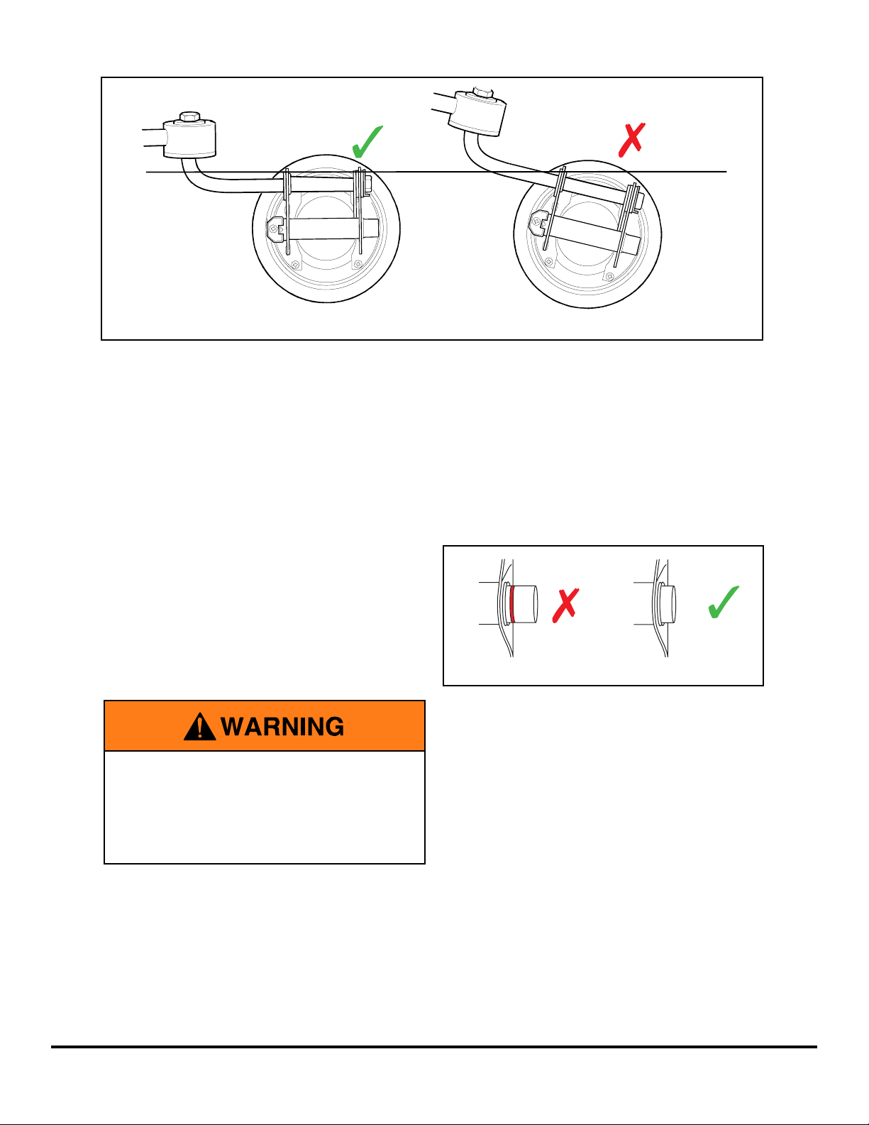
• Clean the glass on which the lil-BUDDY PRO1 is to be mounted to, ensure there is no
dust or dirt that will affect the strength of grip.
• Completely close the window on which the Base Pivot Cup is to be mounted. If the window
is slightly open, there could be movement in the Base Pivot Cup that provides an unstable
lift for the technician.
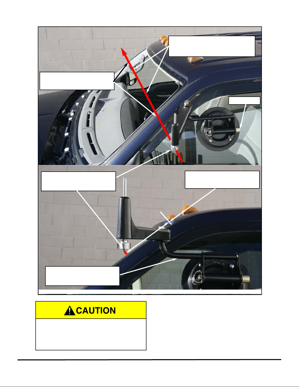
• Ensure that the door on which the Base Pivot Cup is to be mounted is completely closed.
• Place some tape or retention strips on either side of the vehicle roof to use once the new
windshield has been fitted.
• Place the new windshield on a cradle to the side of the vehicle in readiness for placement.
• Locate two lil BUDDY Jr. suction cups to help with lifting the replacement windshield.
Health And Safety
• To avoid the risk of harm to bystanders, make sure that people are kept away from the
working area while the glass replacement is in progress.
• Wear safety gloves to protect the hands.
• Wear safety glasses to protect the eyes.
Setting Up The Lil Buddy
Always follow the guidelines below when
using the lil-BUDDY PRO1.

December 2008 Attaching The Base Pivot Cup |5
The Base Pivot Cup is normally mounted on the drivers door glass of a vehicle. Windshield
installation can be done with the Base Pivot Cup mounted on the passenger door glass of a
vehicle with the passenger side model. Drivers side model shown in this manual.
1. Pin Swing Arm into position. See figure 1.
2. Use the Base Pivot Cup to measure 9 inches from the top of the windshield pillar down
the side of each windshield side pillar. Use tape, your finger or a grease pen to mark
both side pillars. See figure 2.
The measurements should NOT include any molding or trim present; it should be taken
from where the edge of the glass will be placed.
Attaching The Base Pivot Cup
FIGURE 2 - 9 INCH MEASUREMENT
FIGURE 1 - SWING ARM PINNED INTO PLACE
Swing Arm pin

6|Attaching The Base Pivot Cup Decemeber 2008
2. Move the Base Pivot Cup and position it on the side window so that:
• The Base Pivot Cup is parallel with the ground. Use the handle grip to visually
achieve this. See figure 3.
• The red dot on the Swing Arm is in line with the 9” mark on both windshield side
pillars. See figure 5.
3. Light pressure can be used on the cup to keep it in place on the door glass while it is
being positioned correctly.
4. When you are completely happy with the position, firmly fix the cup by doing the
following:
• Push the pump several times, rapidly.
As you do so the air between the cup
and the glass will be removed and
the amount of the button showing will
gradually reduce.
• Keep pushing the pump until you can
no longer see the red line.
5. Pull the pin locking the Swing Arm into place so it is ready for windshield installation.
FIGURE 3 - BASE PIVOT CUP ANGLE
FIGURE 4 - PUMP CUP TO SECURE
After Base Pivot Cup has been secured to
the door glass, check placement to
ensure proper red dot location. If red dot
is not in-line with both windshield side
pillar markings, repeat steps 2 through 4.

December 2008 Attaching The Base Pivot Cup |7
9 inch measurement
mark on windshield side pillars.
Red dot on swing arm must be
in-line with 9” measurements on
both windshield side pillars.
9 inch measurement
on windshield side pillars.
Pump here
Base Pivot Cup should be
parallel with the ground.
FIGURE 5 - BASE PIVOT INSTALLATION
Swing Arm location must be correct for
proper windshield placement. See
troubleshooting section for additional
information.
Eye sight line: Line up marks on both
windshield side pillars and the red dot
on Swing Arm.

8| Attaching The Sliding Rod Cup December 2008
The Sliding Rod cup is placed on the new windshield before starting to lift it into position.
1. Position a cradle close to the left-hand side of the vehicle and place the new windshield
on it, with the outer side facing upwards.
2. On the right-hand side of the windshield, using the red line marked on the collapsed
Sliding Rod measure down 7 inches from the top. Mark with your finger or a grease
pen. See figure 7.
When taking this measurement:
• The rod should NOT be extended.
• The distance measured should NOT include any moulding or trim present; it should
be taken from where the glass starts.
Attaching The Sliding Rod Cup
7 inch measurement
Before installing the Sliding Rod Cup,
ensure that the outside of the windshield
is clean.
FIGURE 6 - WINDSHIELD POSITION
FIGURE 7 - WINDSHIELD MEASUREMENT

3. Move the Sliding Rod Cup and position it on the glass so that:
• The rod is parallel to the windshield top edge. See figure 8.
• The center of the rod is centered on the 7 inch mark. See figure 8.
• The Lil Buddy lable on the rod is just on the edge of the windshield. See figure 8.
December 2008 Attaching The Sliding Rod Cup |9
FIGURE 8 - SLIDING ROD CUP INSTALLATION
lil-BUDDY Sticker
7 inch measurement
to center of rod
Pump here
Correct Position - PRO1 Model Shown
Incorrect Position - PRO Model Shown
FIGURE 9 - SLIDING ROD CUP INCORRECT INSTALLATION
14 inch measurement
to center of rod
Red line on Sliding
Rod housing

10 | Attaching The Sliding Rod Cup December 2008
4. When you are completely happy with the position, firmly fix the cup by doing the
following:
• Push the pump several times, rapidly.
As you do so the air between the cup
and the glass will be removed and
the amount of the button showing will
gradually reduce.
• Keep pushing the pump until you can
no longer see the red line.
5. Attach two lil Buddy Jr. suction cups to the other side of the windshield. They can be
placed wherever you like, as long as they are shoulder width apart. So put them where
they feel most comfortable for you when lifting and moving the windshield. See figure
11.
6. Use one of the lil Buddy jr. suction cups and the handle on the Sliding Rod Cup, to turn
the windshield over and round so that the Sliding Rod Cup is closest to the car.
FIGURE 10 - PUMP CUP TO SECURE
FIGURE 11 - LIL BUDDY JR. PLACEMENT
After Sliding Rod Cup has been secured
to the windshield, check placement to
ensure proper rod location. If rod
movement occurred, repeat
steps 3 and 4.
lil BUDDY Jr. hand suction cups MUST BE
placed shoulder width apart for proper
windshield leverage.

With both Lil Buddy components in place, take some time to visually check everything is
correct. This is the time to make any final adjustments and corrections to ensure a
straight-forward replacement.
• Make sure the two units are positioned correctly on the glass.
• Ensure the red line on the pump of each unit is not showing. If it is, the cup is not
totally secure on the glass. To rectify it, push the pump a few times, rapidly, unit the red
line is no longer in view.
• Ensure you have placed some tape or retention strips either side of the vehicle roof.
These will be used to prevent slippage once the new windshield has been fitted.
Final Checks
Visually check cup seals before setting
windshield into place. A red line showing
on the cups brass pump rod indicates a
bad seal. DO NOT use the Lil-Buddy with
a bad seal.
December 2008 Final Checks |11

12 |Using The Lil Buddy December 2008
NOTE: It is advisable to do a test-run of putting the new windshield in place prior to gluing. This
is so you can work out the exact manoevring required without having to worry about
accidentally smudging glue on the paintwork.
1. Turn the windshield over on the cradle and prep for windshield for installation, apply
glue.
2. If necessary, move the cradle with the windshield close to the side of the vehicle where
the Base Pivot Cup is attached to the door glass.
3. Adjust the end of the rod so it is the correct way for placing onto the Base Pivot Cup.
The side with the deeper cut-out needs to be facing upwards; the side of the shallower
cut-out need to be facing downwards. There should be a sticker on the rod end showing
which side is up. See figure 12.
4. Fully extend the sliding rod and carefully place the rod end onto the pin at the end of
the Swing Arm. See figure 13.
Using The Lil Buddy
FIGURE 12 - SLIDING ROD END
FIGURE 13 - INSTALLATION OF SLIDING ROD END TO SWING ARM
Visually check cup seals before setting
windshield into place. A red line showing
on the cups brass pump rod indicates a
bad seal. DO NOT use the Lil-Buddy with
a bad seal.

5. While using both lil Buddy Jr. suction cups, properly lift the windshield and gradually
move away from the vehicle to extend the sliding rod out for optimum clearance.
6. Gradually move around the front of the vehicle. Stay close to the vehicle as you go and
ensure you lift the windshield enough to clear the vehicle, but DO NOT lift it high.
7. When you get to the front tire on the other side of the vehicle, push back on the Swing
Arm so it moves around and away from the vehicle. Swing Arm should be positioned
approximatly where it was when Base Pivot Cup was installed. See figure 15.
8. Continue to push back on the arm to reduce the rod length. At the same time,
manoeuvre the windshield so it hovers above its final position. See figures 15 and 16.
December 2008 Using The Lil Buddy |13
FIGURE 14 - WALK WINDSHIELD INTO POSITION
DO NOT hold windshield high
over the body.
Keep windshield close to vehicle while
walking around vehicle.
FIGURE 15 - WALK WINDSHIELD INTO POSITION
Push back on Swing Arm to move it
away from vehicle.
DO NOT allow windshield to drag the
glue on top drivers side of vehicle.
Swing Arm location must be correct for
proper windshield placement. See
troubleshooting section for additional
information.

14 |Using The Lil Buddy December 2008
9. Use the following sequence to drop the windshield into its final position.
• Set the top corner of the windshield into place.
• Move the windshield, as necessary, to position it correctly over the bottom corner.
• Set the bottom corner into place.
10. Place the retention strip or tape from the vehicle roof across the top of the vehicle and
windshield to prevent it slipping while the glue is bonding.
11. Walk around to the other side of the vehicle.
FIGURE 17 - WALK WINDSHIELD INTO POSITION
DO NOT set bottom of windshield first. Set top of windshield first. Should have
approximately 2 inches of equal clearance.
2 inches
FIGURE 16 - COLLAPSE SLIDING ROD
Hold lower cup in position or
slightly pull toward you.
Push upper cup away from you
to collapse Sliding Rod.

12. Take hold of the black Sliding Rod Housing and support the weight of the windshield.
Release the Swing Arm pin and pivot arm out of the way. See figure 18.
13. As you drop the Sliding Rod Housing, fit the windshield into its final postion by lining-up
the top corner and then placing the whole side into position in one operation.
14. Place the second retention strip or tape across the top of the vehicle and windshield.
15. Remove the Base Pivot Cup and Sliding
Rod Cup from the glass by pressing the
release levers. You could also use your
finger to break the seal between the cup
and glass. See figure 19.
16. Put the units immediately into the carry
case.
December 2008 Using The Lil Buddy |15
FIGURE 18 - SWING ARM PIN RELEASE
Turn clockwise on Swing Arm pin and
then pull down to release.
Once Swing Arm pin is released pivot Swing
Arm out of the way.
FIGURE 19 - RELEASE CUPS
DO NOT touch extended (silver) portion
on the Sliding Rod. ALWAYS hold black
Sliding Rod Housing.

Every 50 Sets or 30 Days
1. Extend and clean sliver Sliding Rod.
See figure 20.
2. Lubricate black Sliding Rod Housing.
Spray approximately 2 to 3 seconds into
housing to ensure full lubrication of
seals. Use CRC TrueTap Foamy Cutting
Fluid or specific lil Buddy lubricate. See
figure 20.
Every 1000 Sets or 1 Year
1. Preform 30 days maintenace.
2. Lubricate Swing Arm needle bearings.
Check for worn bearings, replace as
needed. See figure 21.
Maintenace
16 |Maintenance December 2008
DO NOT touch extended (silver) portion
on the Sliding Rod. ALWAYS hold black
Sliding Rod Housing.
Be sure to clean up excess oil after
lubricating Sliding Rod.
Clean silver Sliding Rod Lubricate inside wall of
black housing
Lubricate plastic
housing end
After lubication; slowly collapse silver
Sliding Rod allowing excess oil to escape
out the end of black Sliding Rod Housing.
BEWARE oil will spray out the black
Sliding Rod Housing if collapsed to fast.
FIGURE 20 - SLIDING ROD LUBRICATION
Remove Swing Arm using 13/16 inch wrench Check and lubricate needle bearings
FIGURE 21 - SWING ARM NEEDLE BEARINGS
Wear Item -
Replace if worn
Needle bearing -
one per side
Use Blue Loctite on threads when
re-installing Swing Arm bolt.

Troubleshooting
December 2008 Troubleshooting |17
Problem Probable Cause Solution
1. Windshield is hovering to a. Base Pivot Cup mounted to low. a. Adjust Base Pivot Cup
close (low) to side of vehicle on door glass. See figure 22.
where lil BUDDY is mounted. b. Sliding Rod Cup mounted to high b. Adjust Sliding Rod Cup
on windshield. See figure 23.
c. Swing Arm swung to far back c. Adjust Swing Arm
See figure 24.
2. Windshield is hovering to far a. Base Pivot Cup mounted to high a. Adjust Base Pivot Cup
(high) from side of vehicle on door glass. See figure 25.
where lil BUDDY is mounted. b. Sliding Rod Cup mounted to low b. Adjust Sliding Rod Cup
on windshield. See figure 26.
FIGURE 22 - BASE PIVOT CUP MOUNTED TO LOW
Base Pivot Cup mounted to low.
Notice: Red Dot on Swing Arm below pillar. Result: Windshield to close to glue.
FIGURE 23 - SLIDING ROD CUP MOUNTED TO HIGH
Sliding Rod Cup mounted to high.
Notice: Less then 7 inches from top of
windshild to centerline of rod.
Result: Windshield to close to glue.

18 |Troubleshooting December 2008
FIGURE 24 - IN-CORRECT SWING ARM POSITION
Notice: Swing Arm swung to far to rear of vehicle.
Result: Windshield to close to glue.
FIGURE 25 - BASE PIVOT CUP MOUNTED TO HIGH
Base Pivot Cup mounted to high.
Notice: Red Dot on Swing Arm above pillar. Result: Windshield to high from glue.
FIGURE 26 - SLIDING ROD CUP MOUNTED TO LOW
Sliding Rod Cup mounted to low.
Notice: More then 7 inches from top of
windshild to centerline of rod.
Result: Windshield to high from glue.
Table of contents
Popular Cleaning Equipment manuals by other brands

J.P. SELECTA
J.P. SELECTA ULTRASONS 0,24 L instruction manual

Alfalaval
Alfalaval Toftejorg SaniJet 25 Original manual

Kärcher
Kärcher PST 222 manual

Ultrawave
Ultrawave hygea d3ntal Operator's instruction manual

Streamline
Streamline STREAMVAC WVD-961-230-051-EU instruction manual

Kärcher
Kärcher ICH 120/14 Ps F2 manual