Liliput E 44 Series User manual

Bachmann Europe Plc
N 1:160 1
Betriebsanleitung
L162540...49
Elektrolokomotive Baureihe E44
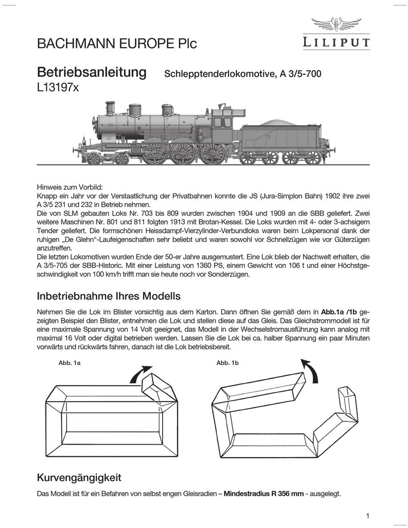
Hinweis zum Vorbild:
Die bis etwa 1930 gebauten Elektrolokomotiven hatten entweder direkten Stangen- oder Blindwellenantrieb
mit einem Großmotor. Die sich abzeichnende Weltwirtschaftskrise zwang einerseits zu Sparsamkeit bei den
Materialien und anderseits sollte langfristig auch die Endgeschwindigkeit der Lokomotiven gesteigert werden.
Dies konnte nicht mit den alten Antriebssystemen realisiert werden. Nach erfolgreicher Erprobung der Probe-
lok E44 101 mit zweiachsigen Drehgestellen und je einem Motor pro Achse wurden weitere Vorserien-Loks
ab 1933 in zwei verschiedenen Versionen E44 102-105 und E44 106-109 gebaut. Alle Vorserien-Loks waren
ohne Vorbau, erst die Serienlokomotiven erhielten den für die E44 typischen Vorbau.
Nachdem von der Serienlok E44 mit Vorbau mehr als 100 Stück gebaut wurden, mussten die Vorserien-Loks
ab 1938 in E44 501-509 umbenannt werden. Die Loks waren hauptsächlich im Betriebswerk Freilassing be-
heimatet und kamen von da bis nach Salzburg, Berchtesgaden und Innsbruck. Die E44 503 und 504 waren
von 1946 bis 1950 in Garmisch stationiert. Die Lokomotiven haben bis Ende der 70-er, Anfang der 80-er
Jahre ihren Dienst getan. Die E44 502 steht als Denkmal-Lok im Bahnhofsbereich von Freilassing.
Nehmen Sie die Lok im Blister vorsichtig aus
dem Karton. Dann öffnen Sie bitte gemäss
dem in Abb. 1 gezeigten Beispiel den Blister,
entnehmen die Lok und stellen diese auf das
Gleis. Das Gleichstrommodell ist für eine ma-
ximale Spannung von 14 Volt geeignet. Las-
sen Sie die Lok bei ca. halber Spannung ein
paar Minuten vorwärts und rückwärts fahren,
danach ist die Lok betriebsbereit.
Abb. 1
Inbetriebnahme Ihres Modells

Bachmann Europe Plc
2 N 1:160
Wartung und Pflege Ihres Modells
Um eine lange Lebensdauer zu gewährleisten, sollte Ihr Modell in regelmäßigen Abständen gewartet
werden.
Das Modell muss dazu nicht geöffnet werden. Vielmehr genügt es, wie nach Abb. 2, das Modell umge-
dreht auf eine weiche Unterlage zu legen ohne dabei Dachaufsteckteile und die Pantographen zu beschä-
digen und mit einem in Spiritus getränkten Wattestäbchen die Radkontakte zu säubern. Danach reinigen
Sie die Räder. Drehen Sie aber bitte auf keinen Fall die Antriebsräder von Hand durch. Nach dem Reinigen
schmieren Sie bitte die in Abb. 3 bezeichneten Lagerstellen ( L) und Getriebeteile ( G) mit einem Tropfen
Maschinenöl. Verwenden Sie handelsübliche Öler mit feiner Kanüle oder eine Stecknadel. Achtung, kein
Speiseöl oder Hautcreme verwenden. Sinnvoll ist es, diese Wartungsarbeiten nach ca. 30-40 Stunden
Betriebszeit durchzuführen.
Abb. 2
Um die folgenden Wartungsarbeiten gut
durchführen zu können ist es notwendig das
Lokgehäuse vom Fahrgestell abzunehmen.
Legen Sie dazu nach Abb. 2 das Modell mit
den Dach nach unten auf eine weiche Un-
terlage ohne die empfindlichen Dachteile zu
beschädigen. Danach fahren Sie mit den bei-
den Daumennägel zwischen Lokgehäuse und
Fahrgestell und ziehen die Gehäusewände
etwas auseinander. In dieser Stellung greifen
Sie dann bitte mit zwei weiteren Fingern unter
die Puffer und ziehen das Fahrgestell aus
dem Lokgehäuse.
Öffnen der Lok
Abb. 3
Abb. 3
LL L L
L L LL GG GG
Abb. 2

Bachmann Europe Plc
N 1:160 3
Abb. 5
Von Zeit zu Zeit ist es auch ratsam die bei-
den Getriebeschnecken Abb. 4 am Motor
zu ölen. Dazu müssen Sie das Lokgehäuse
nach Abb. 2 entfernen.
Abb. 4
Wenn das Lokgehäuse nach Abb. 2 entfernt ist drehen Sie bitte die Schrauben S1 nach Abb. 6 aus. Da-
nach trennen Sie nach Abb. 5 die beiden Stecker PCB2 von der Platine PCB1. Anschliessend entfernen
Sie die vier Schrauben S2 und die beiden Motorhalter MH. Danach können Sie den Motor mit der Leiter-
platte PCB1 entnehmen. Die zwei Kontaktlitzen vom Motor sind auf der Leiterplatte verlötet. Trennen Sie
die Lötstellen auf und löten Sie die Litzen vom neuen Motor nun hier an. Achten Sie dabei auf die Farb-
kennzeichnung der Litzen. In umgekehrter Reihenfolge können Sie nun wieder alle Teile montieren.
Auswechseln des Motors
PCB2
MH
S2
S2
MH
M

Bachmann Europe Plc
4 N 1:160
Sollte es einmal notwendig sein die Drehgestelle
zu wechseln so entfernen Sie zunächst das Lok-
gehäuse nach Abb. 2. Danach ziehen Sie die
Teile Plinks und rechts nach Abb. 6 aus dem
Fahrgestell. Danach ziehen Sie die Stecker PCB2
von der Platine PCB1. Die Achse Anach Abb. 7
schieben Sie mit einen kleinen Schraubendreher
durch das Fahrgestell. Nun ist das Drehgestell frei
und kann entnommen werden. Die Wiedermon-
tage erfolgt in umgekehrter Reihenfolge.
Auswechseln der Drehgestelle
Abb. 7
Legen Sie dazu das Modell mit den Dach nach
unten auf eine weiche Unterlage ohne die emp-
findlichen Dachteile zu beschädigen. Danach
können Sie nach Abb. 8 die Abdeckkappe Cvom
Drehgestell ausklipsen und den Radsatz mit dem
Haftreifen entnehmen. Nach dem Austausch des
Haftreifens können Sie alle Teile wieder in umge-
kehrter Reihenfolge montieren. Beachten Sie bitte
die Lage der Haftreifen vor der Demontage. Nur
die richtige Wiedermontage in die richtige Position
garantiert gute Zug- und Fahreigenschaften.
Auswechseln der Haftreifen
Abb. 8
Beachten Sie bitte, dass für nachträglich eingebaute Teile (z.B. Decoder) keine Haftung übernommen wird.
LILIPUT wünscht Ihnen viel Freude mit Ihrem E44-Modell.
C
A
PCB2
Wenn das Lokgehäuse nach Abb. 2 entfernt ist,
finden Sie auf der Hauptplatine die Schnittstelle
nach der neuesten Norm NEXT18. In Abb. 6
sehen Sie den montierten Brückenstecker für die
Funktion mit Gleichstrom.
Ziehen Sie diesen Brückenstecker ab und stecken
den Digital-Decoder auf. Beachten Sie bitte exakt
die Einbauanleitung des Decoderherstellers. Zu
Fragen der Funktion und zum Einbau kontaktieren
Sie bitte Ihren Decoderlieferanten oder Hersteller.
Einbau eines DCC-Decoders
Abb. 6
PCB1
S1
NEXT18
S1
P

Bachmann Europe Plc
N 1:160 5
Instruction sheet
L162540...49
Electric Locomotive Class E44
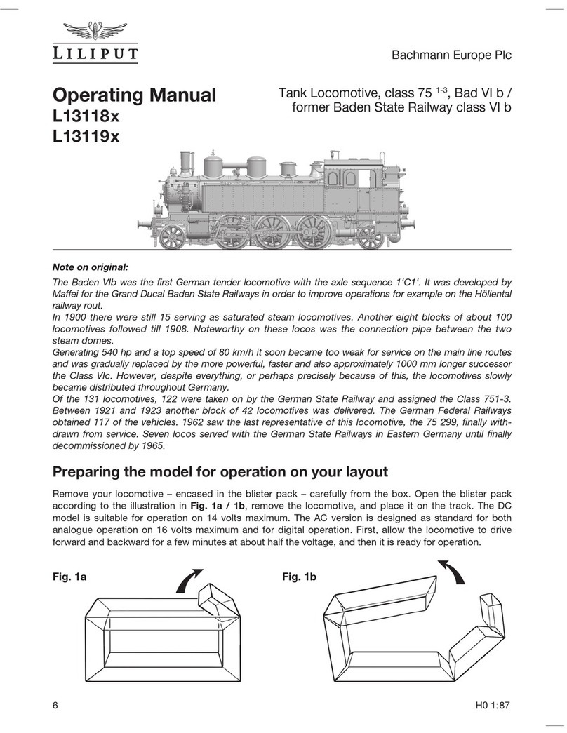
Note on original:
The electric locomotives built until around 1930 either had direct rod or jackshaft drive with a large motor. The
looming economic crisis forced, on the one hand, a frugal use of materials and, on the other hand, the top
speed of the locomotives were also to be increased over the long term.
This could not be achieved with the old drive systems. Following successful testing of the prototype loco-
motive E 44 101 with two axle bogies and one motor per axle, further pre-series locomotives were built from
1933 onwards in two different versions: E 44 102 – 105 and E 44 06 – 109. All pre-series locomotives were
without front projection, only the series locomotives were produced with the front typical of the E 44.
After more than 100 were built of the E 44, the pre-series locomotives had to be renamed from 1939 and
became E 44 501 - 509. The locomotives were mainly based at the factory works in Freilassing and from
there ventured as far afield as Salzburg, Berchtesgaden and Innsbruck. The E 44 503 and 504 were stationed
in Garmisch from 1946 until 1950. The locomotives were in service until the late seventies and early eighties.
The E 44 502 is on display at the railway station in Freilassing.
Carefully remove the locomotive in the blister
pack from the box. Then open the blister
pack as shown in the example in Pic. 1, re-
move the locomotive and place it on the rails.
The vehicle is designed for direct current and
a voltage of 14 volts. Allow the locomotive
to run backwards and forwards at about half
voltage for a few minutes. The vehicle is then
ready for use.
Pic. 1
Putting your model into operation

Bachmann Europe Plc
6 N 1:160
Looking after your model
In order to ensure that your model functions correctly over a long period your model should be maintained
at regular intervals.
The model need not be opened to do this. It is sufficient, as shown in Pic 2, to place the model upside
down on a soft surface being careful not to damage the roof attachments and the pantographs and to
clean the wheel contacts using cotton buds soaked in spirits. Then clean the wheels. Please do not turn
the drive wheels by hand in any circumstances. After cleaning please use a drop of machine oil to lubricate
the bearing points (L) and gear parts (G) shown in Pic. 3. Use commercially available oils and use a fine
cannula or a needle. Caution: do not use cooking oil or hand cream. It is advisable to carry out maintenance
work after approximately 30-40 hours of operation.
Pic. 2
In order to be able to carry out the following
maintenance work it is necessary to remove
the loco body from the chassis. To do this
place the model upside down on a soft sur-
face making sure not to damage sensitive
roof parts as shown in Pic. 2. Then run down
between loco body and chassis with both
thumb nails and prise the body walls apart
slightly. At this stage please use two further
fingers to grip under the buffers and remove
the chassis from the loco body.
Opening the locomotive
Pic. 3
Pic. 3
LL L L
L L LL GG GG
Pic. 2

Bachmann Europe Plc
N 1:160 7
Pic. 5
It is also advisable to occasionally oil the two
gear worms Pic. 4 on the motor. To do this
you must remove the loco body as per Pic. 2.
Pic. 4
Once the loco body has been removed as in Pic. 2 please remove the screws S1 as per Pic. 6. Then se-
parate the two jumpers PCB2 from the main board PCB1 as shown in Pic. 5. Now remove the four screws
S2 and the two motor brackets MH. Afterwards the motor and the main board PCB1 can be removed. The
two contact wires on the motor are soldered to the main board. Separate the soldering points and now
solder the wires of the new motor here. Pay attention to the colour coding of the wires when doing this.
You can now refit all parts by carrying out the above sequence in reverse.
Changing the motor
PCB2
MH
S2
S2
MH
M

Bachmann Europe Plc
8 N 1:160
Should it be necessary to change the bogie,
please first remove the loco body as in Pic. 2.
Then pull the parts Pleft and right as in Pic. 6
from the bogie. Afterwards pull the jumpers
PCB2 from the main board PCB1. Use a small
screwdriver to push the axle Aas per Pic. 7
through the bogie. The bogie is now free and
can be removed. Refitting is effected by follo-
wing the sequence in reverse.
Changing the bogies
Pic. 7
To do this place the model upside down on a
soft surface making sure not to damage sensitive
roof parts. You can then unclip the cover flap C
from the bogie as shown in Pic. 8 and remove the
wheel set with the traction tyres. Once you have
replaced the traction tyres you can refit all parts
by following the above sequence in reverse.
Please note the position of the traction tyres
before disassembly. Only correct refitting in the
right position can guarantee good traction and
driving properties.
Changing the traction tyres
Pic. 8
Please note that no liability can be assumed for any parts subsequently fitted (e.g. decoder).
LILIPUT hopes that your E44 model will give you a lot of pleasure.
C
A
PCB2
Once the loco body has been removed as shown
in Pic. 2 you can find on the main board the inter-
face in its latest standard NEXT18. Pic. 6shows
the jumper configuration for DC operation.
Remove this jumper and plug in the digital deco-
der. Please make sure you follow the installation
instructions of the decoder manufacturer exactly.
For questions regarding function and installation,
please contact the decoder supplier or manufac-
turer.
Installation of a DCC Decoder
Pic. 6
PCB1
S1
NEXT18
S1
P

Bachmann Europe Plc
N 1:160 9
R(F) 1
M+ 2
AUX1 3
AUX3 4
GND 5
U+ 6
AUX7 7
FLED 8
L(F) 9
R(R)
18
RLED
17
AUX5
16
U+
15
GND
14
AUX4
13
AUX2
12
M-
11
L(R)
10
CON1
CON-XS 2X9P 0.5
R
R
L
L
Next18P DCC Dummy
L
LED2
Y
LED1
Y
LED3
Y
R3
4.7K/0805
R2
1.5K/0805
R1
4.7K/0805
C1
105/0805
C2
105/0805
C3
105/0805
D2
S1A
D1
S1A
R8
470 OHM/1210
R7
470 OHM/1210
R5
220K/0805
R6
220K/0805
D3
S1A
D4 S1A
LED4
Y
R4
1.5K/0805
C4
105/0805
Front Panel
Rear Panel
Yellow LED
Top LED Option
Top LED Option
R
R
L
A
-
+
MOTOR
L1
6.8uH
L2
6.8uH
C7
0.1uF/0805
C8
0.1uF/0805
M+
M-
R(F) 1
M+ 2
AUX1 3
AUX3 4
GND 5
U+ 6
AUX7 7
FLED 8
L(F) 9
R(R)
18
RLED
17
AUX5
16
U+
15
GND
14
AUX4
13
AUX2
12
M-
11
L(R)
10
CON1
CON-XS 2X9P 0.5
Yellow LED
Should your LILIPUT model be faulty or not work properly or require repair, you can either
contact
the dealer from whom you purchased the product or contact the customer services
department
directly of one of the following addresses below.
Warranty Conditions:
This LILIPUT model has a warranty of two years from the date of purchase on repairs and parts, as long as it was purcha-
sed from an authorised dealer and if this certificate has been stamped with the address of the dealership and the date of
purchase has been entered. The warranty permits Bachmann Europe Plc either to rectify any fault or to replace the faulty
parts. Further claims are excluded.
Please note that no liability can be assumed for any parts subsequently fitted or for any damage caused thereby.
GREAT BRITAIN
AND ALL OTHER COUNTRIES
(EXCEPT GERMAN SPEAKING COUNTRIES)
BACHMANN EUROPE PLC
MOAT WAY, BARWELL
GB - LEICESTERSHIRE LE9 8EY
Dealer’s stamp with day of purchasing
Warranty Coupon GB
Schaltplan Für alle, die sich noch mehr vertiefen wollen haben wir hier im Anschluss den kompletten
Schaltplan für die Versionen in Gleichstrom (DC) mit der Schnittstelle und den Brückenstecker abgebildet.
Circuit diagram For all those who
want to know more, we have included the
complete circuit diagram for the DC versions
with the interface and the jumpers.

Bachmann Europe Plc
10 N 1:160
Garantiebedingungen:
Dieses LILIPUT-Modell hat ab Kaufdatum zwei Jahre Garan-
tie auf Reparaturen und Teile, sofern es bei einem autorisier-
ten Händler gekauft wurde und dieses Zertifikat vom Händler
abgestempelt und das Kaufdatum eingetragen worden ist.
Die Garantie umfasst nach Wahl von Bachmann Europe Plc
entweder die Beseitigung eines eventuellen Mangels oder
den Ersatz schadhafter Teile. Weitergehende Ansprüche sind
ausgeschlossen.
Beachten Sie bitte, dass für nachträglich eingebaute Teile
(z.B. Decoder oder Lautsprecher) sowie für dadurch entstan-
dene Schäden keine Haftung übernommen wird.
Kaufdatum mit Händlerstempel
DEUTSCHLAND:
BACHMANN EUROPE PLC
NIEDERLASSUNG DEUTSCHLAND
AM UMSPANNWERK 5
D - 90518 ALTDORF BEI NÜRNBERG
ÖSTERREICH:
DOLISCHO MODELLSPIELWAREN
BAHNSTRASSE 4
A - 2340 MÖDLING
SCHWEIZ:
MODELLBAU UND
ELEKTRONIK
STETTBACHSTRASSE 193
CH - 8051 ZÜRICH
ALLE ANDEREN LÄNDER:
BACHMANN EUROPE PLC
MOAT WAY, BARWELL
GB - LEICESTERSHIRE LE9 8EY
Garantie-Schein
Sollte Ihr LILIPUT-Modell einen Mangel oder eine Störung aufweisen oder einmal reparaturbe-
dürftig sein, haben Sie die Möglichkeit, sich diesbezüglich entweder an den Händler, bei dem
Sie das Produkt gekauft haben oder direkt an die Kundendienstabteilung einer der nachfolgend
angegebenen Adressen zu wenden.
Wichtig! Wir empfehlen die Originalverpackung aufzubewahren,
sie ist der beste Schutz für Ihr Modell, wenn dieses nicht gerade
auf Ihrer Anlage unterwegs ist. Beim Betrieb der Lok auf Tep-
pichböden kann die feine Mechanik durch Fasern zerstört wer-
den. Änderungen in Konstruktion und Ausführung vorbehalten.
Bitte bewahren Sie diese Beschreibung zum späteren Gebrauch
auf. Dieses Produkt wurde nach Vorschriften der europäischen
Spielzeugrichtlinien (CE) hergestellt. • Important! We recom-
mend that you keep the original box. It is the best place to store
your model, when it is not in use. Please be aware, that carpet
fibres can destroy the fine mechanism of the locomotive. Sub-
ject to changes in design, version and technical data. Please
retain these data and instructions for further reference. This
product has been manufactured according to the
European toy Safety Directive (CE). • Importante!
Raccomandiamo di tenere la scatola originale. E’
il posto migliore in cui tenere il tuo modello quan-
do non è in uso. Fibre di tappeti possono distrug-
BACHMANN EUROPE Plc · Moat Way · Barwell · Leicestershire · LE9 8EY England Made in China
gere il fine meccanismo della locomotiva. Preghiamo di conservare
questi dati ed istruzioni per altre informazioni. Quest’articolo è stato
prodotto in accordo con la Direttiva Europea Sicurezza giochi (CE).
Achtung! Bei unsachmäßigem Gebrauch besteht Verletzungsgefahr
durch funktionsbedingte scharfe Kanten und Spitzen • Attention! At
an incorrect use there exists danger of hurting becauseof cutting edges
and tips • Attention! Il y a danger de blessure à un emploi incorrect
à cause des aiguilles et arêtes vives! • Voorzichtig! Bij ondoelmatig
gebruik bestaat verwondigsgevaar door scherpe zijkanten en uitsteek-
sels! • Attenzione! Un uso improprio comporta pericolo di ferimenti
attraverso punte e spigoli taglienti! • Atencion! Un empleo incorrecto
puede causar heridas debido a las puntas y aristas agudas! • Atençao!
Por utilizaçao incorrecta existe o perigo de estragos, em virtude de cor-
tes nas abas e nas pontas! • Προξοχη! Η ακαταλληλη
χρηοη εγκλειει κινδυνουζ μκροτ ραυματιομων, εξ
αιπαξ κοπτερων ακμων και προεξοχωθν • Bemaerk!
Ved ukorrekt brug kan de funktionsbetingede skarpe
kanter og spidser forfolde skade!
Table of contents
Languages:
Other Liliput Toy manuals

Liliput
Liliput L163971 99 Series User manual

Liliput
Liliput L13156x User manual

Liliput
Liliput L13303 Series User manual

Liliput
Liliput L13197x User manual

Liliput
Liliput L13118x User manual

Liliput
Liliput L13351x User manual

Liliput
Liliput L112801 User manual

Liliput
Liliput L13302 series User manual

Liliput
Liliput L133027 User manual