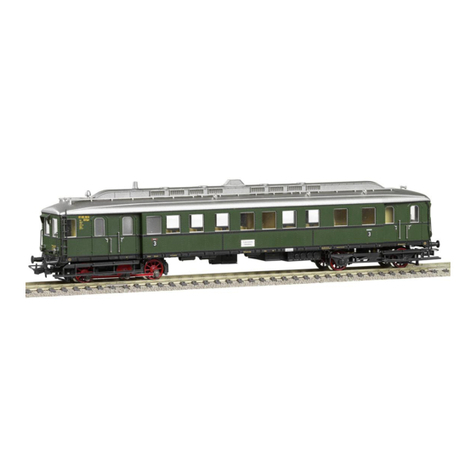
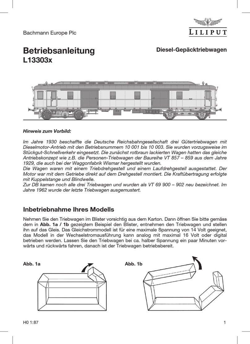
Liliput L13351x User manual

Bachmann Europe Plc
6 H0 1:87
Operating Manual
L13351x
Battery Powered Railcar,
type Wittfeld, 3 units
Information on the original:
The low amount of traffic on many Prussian branch line routes around 1900 meant that the use of
steam trains could no longer be justified. The chief inspector Gustav Wittfeld developed a two-part
railcar with accumulators as an alternative.
These railcars proved so successful that three-part railcars were also built in 1913 / 14 to increase
capacity. This led to a total of eight railcars with a so-called “switching section”. These not only had
3rd class seats but also compartments for post and luggage. In contrast to the two-part versions the
motors on the three-part railcars acted on both central section axles. In the aftermath of the Second
World War just one three-part railcar remained with the DB. It was converted in 1948 and numbered
ETA 178 051. It was based at the Duisburg depot up until its decommissioning in 1960.
Unit B
Fig. 2
Putting your model into operation
For clarity we have removed the car bodies in fig. 1 and fig. 2. The three units A, B and Care packed
individually and must be put together by the purchaser as described below. This is a simple process
effected by electrical contact couplings. All three units are connected mechanically and electrically via
these couplings. Within a unit the electrical connection is generated by an overlying circuit board. This
circuit board also houses the LEDs for the interior lighting. Unit A contains the drive unit; Unit B the
circuit board with the 21-pin NEM 660 port. Represented here is a possible setup with sound decoder
and loudspeaker. Fig. 2 shows a detail view of the car ends.
Fig. 1
Unit C
Unit A

OnOff
Bachmann Europe Plc
H0 1:87 7
Coupling the Units
The three railcar units are blister packed with a top and bottom half. Remove the top and then the
three units. Unit A with motor is located top right. Start by placing the units upside down (roof
down) on a soft surface. The couplings are designed so that the units can only be fitted in the
correct position.
Slide the couplings with the pin and socket row up together and now press the coupling parts (1.)
together using thumb and forefinger. You can clip the cover (2.) in place afterwards. Consult fig. 3.
When all three units have been fitted, you are ready to place the complete railcar on the track. The
direct current model is suitable for a maximum voltage of 14 volts; the alternating current variant can
either be run analogously on 16 volts or digitally. Allow the railcar to run backwards and forwards at
about half voltage for a few minutes. The rail car is then ready for use.
Interior lighting function
As already described above, the railcar is fitted with LED interior lighting as standard. A switch to
turn the lighting on and off is located on the underside of Unit B. If you run your model digitally with
a decoder you can also control he interior lighting from your controller. See fig. 4 for this.
Fig. 4
Fig. 3
2. 1.

Bachmann Europe Plc
8 H0 1:87
Looking after your model
In order to ensure that your model has a long service life, the railcar should undergo maintenance
at regular intervals. The model need not be opened to do this. It is sufficient if the model is turned
upside down and placed on a soft surface as shown in fig. 5. Clean the wheel contacts (A) using
cotton wool buds soaked in spirits and then clean the wheels.
However, please do not turn the drive wheels by hand in any circumstances.
After cleaning please use a drop of machine oil to lubricate the bearing points (B) shown in figure. It
is advisable to carry out this maintenance work after about 30-40 hours running time.
To oil the drive unit in fig. 6 please remove the two screws (C) and remove the bogie plate (E). You
can now oil all bearings (B) and the gears (D). Afterwards, you can refit the bogie plate with the two
screws. The oil will be distributed over the toothed wheels when the railcar runs. Only use standard
oils and a fine cannula or a pin.
Caution: do not use cooking oil or hand cream.
Fig. 5
Fig. 6
AA
BB
BB
AA
C
C
E
C
B
B
D
D
D

Bachmann Europe Plc
H0 1:87 9
Opening the vehicles
The railcar only needs to be opened for the retrofitting of a decoder or to exchange the motor. To
do this it is necessary to dismantle the car body as shown in fig. 7. The car bodies of Unit A and B
are held by means of six clips; Unit C by four. The position of the clips can be recognised by a small
paring (F) in the bogie. See here fig. 8. It is sensible to separate the units and to carry out the requi-
site work on the individual model. Place the unit upside down on a soft surface. Slide a screwdriver
into the gap and by turning gently loosen the car body from the bogie. We suggest from this point
on using paper or thin cardboard so as to ensure that the rail body does not snap back together
again. Now loosen the remaining clips as just described. Afterwards, you can remove the car body
in its entirety. We earnestly suggest this method of proceeding so that none of the many add-on
parts are damaged during this work.
Fig. 7
Fig. 8
Installation of a decoder and loudspeaker
Before installing a decoder, please check all the analogue functions of the railcar. As already
described above the 21-pin NEM 660 port is located in Unit B. After disassembling the rail body,
you will see as in fig. 9 on the main circuit board (G) the port with a jumper.
First remove the loudspeaker holder (H) and then
the jumper on the port. You can now insert the de-
coder into the port. Once you have fitted a sound
decoder clip the loudspeaker of 20 mm diameter in
the holder, and only then fit the loudspeaker again
in Unit B. There are already two pins (J) on the
main circuit board to accept the loudspeaker.
H
G
J
Fig. 9
F

Bachmann Europe Plc
10 H0 1:87
LILIPUT hopes that your railcar model will give you a lot of pleasure.
Assembly of an additional coupling
Normally the Wittfeld railcar travels alone on branch lines. This is why we have not added a coupling
to both car ends as part of the basic equipment on the model and fitted the long brake hose and
coupling imitation on the buffer beam. However, occasionally either a passenger carriage or a goods
wagon was attached. For this option we have included a bag of accessories. With this, the addi-
tional couplings can be moved freely after fitting. First remove the long attachment from the buffer
beam and then fit the short attachments (N) from the accessory bag.
To fit the coupling pocket (O) to the bogie of the drive unit in fig. 10, please remove the screws (C)
and the bogie cover (E). After this you can slide the coupling pocket (O) on the bogie bolt and refit
the bogie cover (E). Nothing needs to be dismantled on the unpowered bogie in fig. 11. Here, you
can fit the bolt (P) with the coupling pocket (O) together from below in the hole designed for this
purpose. Please take care that you only attach a maximum of one carriage as on the original.
Your model as an alternating current version
If you have decided on running your LILIPUT model using a central rail alternating current system,
please observe the following: This model has a digital decoder installed (ESU Lokpilot) which can be
used to power your vehicle either on an analogue basis (16 volt AC) or digitally. Please consult the
instruction sheet supplied by ESU for details on how the decoder works. A slider is fitted to the un-
powered bogie in Unit B for power pickup from the central rail. Fig. 12 shows the slider (K) installed.
The retaining bracket (L) simply snaps into two clip-in lugs. When disassembling in accordance with
fig. 13 please use a screwdriver to gently prise the retaining arm (M) outwards. Naturally, the wheel
profile of the wheel sets has also been adapted to the track system commonly in use.
N
L
K
M
Fig. 12 Fig. 13
N
O
P
Fig. 11
Unit
B
Fig. 10
Unit
A
E
C

D2
1N5819WB
D3 1N5819WB
D1
1N5819WB
D4 1N5819WB
RIGHT RAILWAY
LEFT RAILWAY
R
L
NC
1
NC
11
NC
2
SPEAK2
10
NC
3
SPEAK1
9
NC
4
LEDF
8
NC
5
LEDR
7
NC
6
VCC 12
NC 13
AUX214
AUX115
LED+ 16
NC 17
M- 18
M+ 19
GND20
L21
R22
CONNE#10381
R01
220K/0805
R02
220K/0805
SW1
SWITC#10171
M+
M- +EC1
10UF/35V
R1
2.2K/0805
R7 1.5K/0805
C7 105/0805
C1 105/0805
W
W
R2
2.2K/0603
C2 105/0603
W
R6 1.5K/0805
C6 105/0805
W
R3
2.2K/0603
C3 105/0603
W
R5
2.2K/0603
C5 105/0603
R
R4 2.2K/0603
C4 105/0603
R
A
-
+
M1
C18
104/1206
C17
104/1206
M+
M-
L1
22uH
L2
22uH
DC Connection Diagram
D3800+PCB03
D7
S1A
D8
S1A
NC
1
NC
11
NC
2
SPEAK2
10
NC
3
SPEAK1
9
NC
4
LEDF
8
NC
5
LEDR
7
NC
6
VCC 12
NC 13
AUX214
AUX115
LED+ 16
NC 17
M- 18
M+ 19
GND20
L21
R22
CONNE#10341
CAPAC#TA038
V+
FLED-
RLED-
AUX1
SPK
SPKER#
Unit A
with 21pin Decoder
R14
2.2K/0603
R8
2.2K/0603
C14105/0603
R
W
R13
2.2K/0603
C13105/0603
R
R9
2.2K/0603
C9 105/0603
W
R10
2.2K/0805
C10105/0805
W
R11 1.5K/0805
C11105/0805
W
R12 1.5K/0805
C12105/0805
W
Interior
R16
1.5K/0805
C16105/0805
W
R15 1.5K/0805
C15105/0805
W
AUX1
V+
L
M-
AUX1
RLED-
V+
FLED-
M+
R
L
M-
AUX1
RLED-
V+
FLED-
M+
R
Unit C
C8 105/0603
AC
AC
AC
DC
AC
Unit B
Light
Rear
Light
Front
Light
Top Front
Light
Interior
Light
Interior
Light
Rear
LightFront
Light
Top Front
Light
L
AUX1
RLED-
V+
FLED-
R
L
M-
AUX1
RLED-
V+
FLED-
M+
R
R Wheels
L Wheels
L Wheels
R Wheels
ON/OFF Interior Light
Bachmann Europe Plc
H0 1:87 11
Should your LILIPUT model be faulty or not work properly or require repair, you can either
contact
the dealer from whom you purchased the product or contact the customer services
department
directly of one of the following addresses below.
Warranty Conditions:
This LILIPUT model has a warranty of two years from the date of purchase on repairs and parts, as long as it was purchased
from an authorised dealer and if this certificate has been stamped with the address of the dealership and the date of
purchase has been entered. The warranty permits Bachmann Europe Plc either to rectify any fault or to replace the faulty
parts. Further claims are excluded.
Please note that no liability can be assumed for any parts subsequently fitted or for any damage caused thereby.
GREAT BRITAIN
AND ALL OTHER COUNTRIES
(EXCEPT GERMAN SPEAKING
COUNTRIES
)
BACHMANN EUROPE PLC
MOAT WAY, BARWELL
GB - LEICESTERSHIRE LE9 8EY
Dealer’s stamp with day of purchasing:
Warranty Coupon GB
Circuit diagram

Bachmann Europe Plc
12 H0 1:87
Garantiebedingungen:
Dieses LILIPUT-Modell hat ab Kaufdatum zwei Jahre
Garantie auf Reparaturen und Teile, sofern es bei einem
autorisierten Händler gekauft wurde und dieses Zertifikat
vom Händler abgestempelt und das Kaufdatum einge-
tragen worden ist. Die Garantie umfasst nach Wahl von
Bachmann Europe Plc entweder die Beseitigung eines
eventuellen Mangels oder den Ersatz schadhafter Teile.
Weitergehende Ansprüche sind ausgeschlossen.
Beachten Sie bitte, dass für nachträglich eingebaute Teile
(z.B. Decoder oder Lautsprecher) sowie für dadurch ent-
standene Schäden keine Haftung übernommen wird.
Kaufdatum mit Händlerstempel:
DEUTSCHLAND:
BACHMANN EUROPE PLC
NIEDERLASSUNG DEUTSCHLAND
AM UMSPANNWERK 5
D - 90518 ALTDORF BEI NÜRNBERG
ÖSTERREICH:
DOLISCHO MODELLSPIELWAREN
BAHNSTRASSE 4
A - 2340 MÖDLING
SCHWEIZ:
MODELLBAU UND
ELEKTRONIK
STETTBACHSTRASSE 193
CH - 8051 ZÜRICH
ALLE ANDEREN LÄNDER:
BACHMANN EUROPE PLC
MOAT WAY, BARWELL
GB - LEICESTERSHIRE LE9 8EY
Garantie-Schein
Sollte Ihr LILIPUT-Modell einen Mangel oder eine Störung aufweisen oder einmal reparatur-
bedürftig sein, haben Sie die Möglichkeit, sich diesbezüglich entweder an den Händler, bei dem
Sie das Produkt gekauft haben oder direkt an die Kundendienstabteilung einer der nachfolgend
angegebenen Adressen zu wenden.
Bachmann Europe Plc · Moat Way · Barwell · Leicestershire · LE9 8EY · England Made in China
Wichtig! Wir empfehlen die Originalverpackung aufzubewahren,
sie ist der beste Schutz für Ihr Modell, wenn dieses nicht gerade
auf Ihrer Anlage unterwegs ist. Beim Betrieb der Lok auf Teppich-
böden kann die feine Mechanik durch Fasern zerstört werden.
Änderungen in Konstruktion und Ausführung vorbehalten. Bitte
bewahren Sie diese Beschreibung zum späteren Gebrauch auf.
Dieses Produkt wurde nach Vorschriften der europäischen Spiel-
zeugrichtlinien (CE) hergestellt. • Important! We recommend that
you keep the original box. It is the best place to store your model,
when it is not in use. Please be aware, that carpet fibres can de-
stroy the fine mechanism of the locomotive. Subject to changes in
design, version and technical data. Please retain these data and
instructions for further reference. This product has been manufac-
tured according to the European toy Safety Directive
(CE). • Importante! Raccomandiamo di tenere la
scatola originale. E’ il posto migliore in cui tenere il
tuo modello quando non è in uso. Fibre di tappeti
possono distruggere il fine meccanismo della loco-
motiva. Preghiamo di conservare questi dati ed istruzioni per altre
informazioni. Quest’articolo è stato prodotto in accordo con la
Direttiva Europea Sicurezza giochi (CE).
Achtung! Bei unsachmäßigem Gebrauch besteht Verletzungsgefahr
durch funktionsbedingte scharfe Kanten und Spitzen • Attention!
At an incorrect use there exists danger of hurting because of cutting
edges and tips • Attention! Il y a danger de blessure à un emploi in-
correct à cause des aiguilles et arêtes vives! • Voorzichtig! Bij ondo-
elmatig gebruik bestaat verwondigsgevaar door scherpe zijkanten
en uitsteeksels! • Attenzione! Un uso improprio comporta pericolo
di ferimenti attraverso punte e spigoli taglienti! • Atencion! Un em-
pleo incorrecto puede causar heridas debido a las puntas y aristas
agudas! • Atençao! Por utilizaçao incorrecta existe o perigo de es-
tragos, em virtude de cortes nas abas e nas pontas!
• Προξοχη! Η ακαταλληλη χρηοη εγκλειει κινδυνουζ
μκροτ ραυματιομων, εξ αιπαξ κοπτερων ακμων και
προεξοχωθν • Bemaerk! Ved ukorrekt brug kan de funk-
tionsbetingede skarpe kanter og spidser forfolde skade!
Table of contents
Other Liliput Toy manuals

Liliput
Liliput L112801 User manual

Liliput
Liliput E 44 Series User manual

Liliput
Liliput L133027 User manual

Liliput
Liliput L163971 99 Series User manual

Liliput
Liliput L13156x User manual

Liliput
Liliput L13303 Series User manual

Liliput
Liliput L13118x User manual

Liliput
Liliput L13197x User manual

Liliput
Liliput L13302 series User manual