Liliput L13302 series User manual

Bachmann Europe Plc
6 H0 1:87
Instruction sheet
L13302x
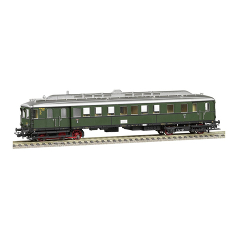
Diesel railcar
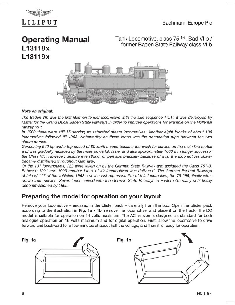
Information on the original:
In 1925/26 the German State Railway (Deutsche Reichsbahn) ordered fifteen 4-axle railcars from
builders Waggonfabrik Wismar. These diesel units were delivered between 1926 and 1928 in two
series (VT 853-861 and VT 866-871). They were powered by a 150 hp Maybach engine, through
a 4-speed mechanical transmission and via a jackshaft connected to both wheelsets in the “lea-
ding” bogie. Railcar no. VT 858 was allocated to the Mainz main station traction depot, Bw Mainz
Hbf, in the State Railway regional directorate (RBD) of Mainz, before being re-allocated to Ober-
lahnstein in 1937. At the beginning of the war, in 1939/40, VT 858 was stored out of service due
to fuel shortages and finally withdrawn from traffic on 28.11.1944. After the war the only example
of the class taken over by the DB was VT 859, which it renumbered VT 65 903. It was not until
December 1951 that the unit was rebuilt, uprated to 210 hp and its maximum speed increased
to 80 km/h. With its new number, VT 62 904, it was then transferred to Friedrichshafen traction
depot and operated on services in that area. It subsequently moved to Brauschweig, where it
worked on branch lines hauling a variety of passenger rolling stock. It was finally withdrawn from
service in 1957 following the discovery of a bogie frame crack.
Putting your model into operation
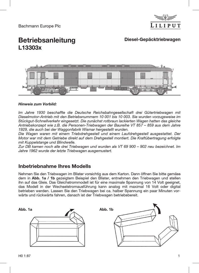
Carefully remove the railcar in the blister pack from the box. Then open the blister pack as
shown in the example in Fig. 1a / 1b, remove the railcar and place it on the rails. The direct
current model is suitable for a maximum voltage of 14 volts, the alternating current variant can
either be run analogously on 16 volts or digitally. Allow the railcar to run backwards and for-
wards at about half voltage for a few minutes. The railcar is then ready for use.
Fig. 1a Fig. 1b

Bachmann Europe Plc
H0 1:87 7
Looking after your model
In order to ensure that your model functions correctly over a long period, your model should
be maintained at regular intervals. The model need not be opened to do this. It is sufficient, to
place the model upside down on a soft surface, being careful not to damage the roof attach-
ments and to clean the wheel contacts using cotton buds soaked in spirits. Then clean the
wheels.
Please do not turn the drive wheels by hand in any circumstances.
After cleaning please use a drop of machine oil to lubricate the bearing points (L) and gear
parts (G1) shown in Fig. 2 + 3. Use commercially available oils and use a fine cannula or
a needle. Caution: do not use cooking oil or hand cream. It is advisable to carry out main-
tenance work after approximately 30-40 hours of operation.
Fig. 3Fig. 2
L
L
LL
LL
G1
L
L
LL
The intermeshing of the toothed wheels transports the oil as far as the motor worm. However,
we suggest that you also oil the motor worm after about two or three maintenance periods.
To do this please, remove the housing from the bogies as shown in Fig. 4.
Opening your model
By inserting your thumbnail between roof corner and housing (X) you can unclip the roof
and lift upwards for removal. Now please insert a screwdriver vertically into the opening (Y1)
and move it in the direction of the arrow (2). This pushes the housing outwards somewhat.
With your thumbnail you can now maintain the distance (Z) you have created between the
bogie and the bottom edge of the housing (G). To splay the opposite housing wall, insert the
screwdriver in the opening (Y3) and move in the direction of the arrow (4). The housing can
now be easily removed from the bogie. You will now be able to see the oil hole at the top of
the gear block (G2).

Bachmann Europe Plc
8 H0 1:87
Fig. 5
Front light system
The railcar was normally used on its own. However, one or other goods trucks was added
on secondary routes. To enable you to also depict the model in this scenario, the front or
rear light can be set depending on the version used. The integrated multiswitch (S) can be
located by removing the cover plate (A) on the underside of the rail car as shown in Fig. 6.
Please pay attention to the circuit diagram for the switch in Fig. 5. The model comes with
the light change white/red in both directions.
Switch
position
1 2 3
ON
4
Light change white/red depending on the direction of travel
1 2 3
ON
4
Only light on the end of car 2, with light change white/red
1 2 3
ON
4
Only light on the end of car 1, with light change white/red
1 2 3
ON
4
Light change white depending on the direction of travel
1 2 3
ON
4
Interior lighting off
1 2
Fig. 4
X
G2
G
2
Y1
Y3
4
GZ

Bachmann Europe Plc
H0 1:87 9
Installation of a DCC Decoder
Directly next to the multi-switch shown in
Fig. 6 on the underside of the railcar is also
the 21-pin interface (D) for the digital deco-
der. After unclipping the cover, the jumper
can be removed and the decoder attached.
When doing this please make sure you follow
the installation instructions of the decoder
manufacturer exactly.
For questions regarding function and instal-
lation, please contact the decoder supplier or
manufacturer.
Fig. 6
Installation of a loudspeaker
The railcar already comes completely pre-
pared for locomotive sound operation. After
fitting the sound decoder as shown in Fig. 6,
the socket (SP1) for the loudspeaker is loca-
ted on the top of the circuit board (M1) as per
Fig. 7.
Use a loudspeaker 16 mm in diameter. Two
pins (SP2) are already fitted to the circuit
board to connect the loudspeaker.
Please also refer to the instructions of the
decoder or loudspeaker manufacturer.
Fig. 7
D
S
SP1 SP2M1
A

Bachmann Europe Plc
10 H0 1:87
Changing the motor
First remove the top circuit board (M1) as
shown in Fig. 8, it is fitted with two screws
to the interior. You can now gently remove
the plugs (M2). In order to be able to re-
move the bogie from below, loosen the two
screws (M3) and remove the retaining lid
(M4). You can now unclip the motor bracket
(M5) on the individual bogies and removed
the motor (M6). Refitting is effected by follo-
wing the sequence in reverse.
If you have decided on a LILIPUT model for
the three rail AC system, please observe the
following:
This model has a digital decoder installed
(ESU Lokpilot) which can be used to power
your vehicle either on an analogue basis
(16 Volt AC) or digitally. Please consult the
instruction sheet supplied by ESU for details
on how the decoder works. For power pick
up from the central rail, the slider has to be
clipped on to the bogie with the aid of a hol-
der (AC1) as shown in Fig. 9. To change the
slider, please slightly press apart the retai-
ning arms (AC2) of the holder using a small
screwdriver. This enables the retaining seat
of the central slider to be removed from the
holder R.
M1
M3
M2
M5
M6
M2
M4
Fig. 8
Your model as an AC variant
Fig. 9
AC1
AC2
LILIPUT hopes that your railcar model will give you a lot of pleasure.
R

Bachmann Europe Plc
H0 1:87 11
L1
4.7uH
L2
4.7uH
C17
0.1UF
C18
0.1UF
C16
0.1UF
C15
0.1UF
1206
M+
M-
1
2
CON10
1
2
JP10
R R
L L
1
2
CON9
1
2
JP9
M+
M+
M-
M-
1
2
3
4
5
6
7
89
10
11
12
13
14
15
16
Socket
CON7
8PINX2(16PIN)
R
MO+
B+
SW1/3
FL-
SW1/1
L
MO-
SW1/4
SW1/2
RL-
GND
+5V
+VDD
SPK-
SPK+
Q1
8550
R19
2.2K
R17
10K
Q1B
D9
LMBR140T1G
D7
LMBR140T1G
C19
0.1U
R3
2.2K
C1
1uF
LED1
White
1
2
3
4
CON5
WHL+
REDF+
HL-
BL-
R2
220K
D6
LMBR140T1G
R6
2.2K C4
1uF
LED7
Red
R5
2.2K C3
1uF
LED3
White
R4
2.2K C2
1uF
LED2
White
R7
2.2K C5
1uF
LED8
Red
Front Panel LEDs
1
2
3
4
JP5
WHL+
REDF+
HL-
BL-
PCB03
Q3B
Q2
8550
R20
2.2K
R16
10K
D10
LMBR140T1G
R8
2.2K
C6
1uF
LED9
Yellow
R10
2.2K
C8
1uF
LED11
Yellow
R9
2.2K
C7
1uF
LED10
Yellow
C20
0.1U
CABL+
R22
2.2K
C22
1uF
LED15
Yellow
R14 2.2K
C13 1uF
LED6 Red
R13 2.2K
C12 1uF
LED5 White
R12 2.2K
C11 1uF
LED4 White
R15 2.2K
C14 1uF
LED14 Red
1
2
3
4
JP6
WBL+
REDB+
BL-
HL-
R1
220K
D8
LMBR140T1G
R11
2.2K
C9
1uF
LED13
White
Q3
8550
R21
2.2K
R18
10K
Q2B
D11
LMBR140T1G
D12
LMBR140T1G
SW1/2
C21
0.1U
1
2
3
4
CON6
WBL+
REDB+
BL-
HL-
SPK+
SPK-
MOTOR
D3303
1
2
3
4
Dip SW
EDA104LZ
Hallsensor#1
1
Hallsensor#2
2
Hallsensor#3
3
SU(AUX4)
4
ZBCLK(TxD)
5
ZBDTA(RxD)
6
Rear Light
7
Front Light
8
Speaker+
9
Speaker-
10
TrkR 22
VCC(5V) 12
AUX313
AUX214
AUX115
U+ 16
Motor3 17
Motor- 18
Motor+ 19
GND20
TrkL 21
CON2
Header(21pin)
1
2
3
4
5
6
7
8
9
10
1112
13
14
15
16
Weiding Pad
J5
16PINPAD-2
R
MO+
B+
FL-
L
MO-
RL-
GND
SW1/3
SPK+
SW1/1
SW1/4
SW1/2
SPK-
+VDD
+5V
TrK R
TrK L
2
1
Trcak-A
Pad
DC & AC Version
Interior Lights
Front Top LEDs
D3303+PCB06
D3303+PCB04
R
L
D3302 Circuit Diagram
Q4
882
DZ1
8.2V
R47
4.7K
C40
0.1U
C41
0.1U
D5
LMBR140T1G
L
R
R
L
21 Pin DCC Ready
Hallsensor#1
1
Hallsensor#2
2
Hallsensor#3
3
SU(AUX4)
4
ZBCLK(TxD)
5
ZBDTA(RxD)
6
Rear Light
7
Front Light
8
Speaker+
9
Speaker-
10
TrkR 22
VCC(5V) 12
AUX313
AUX214
AUX115
U+ 16
Motor3 17
Motor- 18
Motor+ 19
GND20
TrkL 21
CON1
D3800+PCB05
D2
LMBR140T1G X 4
D4
D1 D3
C01
0.1U
EC01
10UF/35V
C02
2.2U25V
C03
2.2U25V
R
L
Q4-B
Dummy Board
Rear Panel LEDs
4 pcs
Rear Top LEDs
Circuit Can be used Step-up
Front & Rear Lights Dummy Board
Rear Panel LEDsFront Panel LEDs
Dip SW Functions
SW.1 Front Panel LEDs
SW.2 Rear Panel LEDs
SW.3 Rear Red Light LEDs
SW.4 Interior LEDs
Option
Option
AC
AC Connect
DC Connect
Connect
SP01
SPEAKER
SPK+
SPK-
PCB03
Should your LILIPUT model be faulty or not work properly or require repair, you can either
contact
the dealer from whom you purchased the product or contact the customer services
department
directly of one of the following addresses below.
Warranty Conditions:
This LILIPUT model has a warranty of two years from the date of purchase on repairs and parts, as long as it was purchased
from an authorised dealer and if this certificate has been stamped with the address of the dealership and the date of
purchase has been entered. The warranty permits Bachmann Europe Plc either to rectify any fault or to replace the faulty
parts. Further claims are excluded.
Please note that no liability can be assumed for any parts subsequently fitted or for any damage caused thereby.
GREAT BRITAIN
AND ALL OTHER COUNTRIES
(EXCEPT GERMAN SPEAKING
COUNTRIES
)
BACHMANN EUROPE PLC
MOAT WAY, BARWELL
GB - LEICESTERSHIRE LE9 8EY
Dealer’s stamp with day of purchasing
Warranty Coupon GB
Circuit diagram

Bachmann Europe Plc
12 H0 1:87
Garantiebedingungen:
Dieses LILIPUT-Modell hat ab Kaufdatum zwei Jahre
Garantie auf Reparaturen und Teile, sofern es bei einem
autorisierten Händler gekauft wurde und dieses Zertifikat
vom Händler abgestempelt und das Kaufdatum einge-
tragen worden ist. Die Garantie umfasst nach Wahl von
Bachmann Europe Plc entweder die Beseitigung eines
eventuellen Mangels oder den Ersatz schadhafter Teile.
Weitergehende Ansprüche sind ausgeschlossen.
Beachten Sie bitte, dass für nachträglich eingebaute Teile
(z.B. Decoder oder Lautsprecher) sowie für dadurch ent-
standene Schäden keine Haftung übernommen wird.
Kaufdatum mit Händlerstempel
DEUTSCHLAND:
BACHMANN EUROPE PLC
NIEDERLASSUNG DEUTSCHLAND
AM UMSPANNWERK 5
D - 90518 ALTDORF BEI NÜRNBERG
ÖSTERREICH:
DOLISCHO MODELLSPIELWAREN
BAHNSTRASSE 4
A - 2340 MÖDLING
SCHWEIZ:
TRAINS SERVICE
PHILIPPE MORISOD
15 CHEMIN DES PALETTES
CH - 1212 GRAND-LANCY
ALLE ANDEREN LÄNDER:
BACHMANN EUROPE PLC
MOAT WAY, BARWELL
GB - LEICESTERSHIRE LE9 8EY
Garantie-Schein
Sollte Ihr LILIPUT-Modell einen Mangel oder eine Störung aufweisen oder einmal reparatur-
bedürftig sein, haben Sie die Möglichkeit, sich diesbezüglich entweder an den Händler, bei dem
Sie das Produkt gekauft haben oder direkt an die Kundendienstabteilung einer der nachfolgend
angegebenen Adressen zu wenden.
Wichtig! Wir empfehlen die Originalverpackung aufzubewahren,
sie ist der beste Schutz für Ihr Modell, wenn dieses nicht gerade
auf Ihrer Anlage unterwegs ist. Beim Betrieb der Lok auf Tep-
pichböden kann die feine Mechanik durch Fasern zerstört wer-
den. Änderungen in Konstruktion und Ausführung vorbehalten.
Bitte bewahren Sie diese Beschreibung zum späteren Gebrauch
auf. Dieses Produkt wurde nach Vorschriften der europäischen
Spielzeugrichtlinien (CE) hergestellt. • Important! We recom-
mend that you keep the original box. It is the best place to store
your model, when it is not in use. Please be aware, that carpet
fibres can destroy the fine mechanism of the locomotive. Sub-
ject to changes in design, version and technical data. Please
retain these data and instructions for further reference. This
product has been manufactured according to the
European toy Safety Directive (CE). • Importante!
Raccomandiamo di tenere la scatola originale. E’
il posto migliore in cui tenere il tuo modello quan-
do non è in uso. Fibre di tappeti possono distrug-
Bachmann Europe Plc · Moat Way · Barwell · Leicestershire · LE9 8EY · England Made in China
gere il fine meccanismo della locomotiva. Preghiamo di conservare
questi dati ed istruzioni per altre informazioni. Quest’articolo è stato
prodotto in accordo con la Direttiva Europea Sicurezza giochi (CE).
Achtung! Bei unsachmäßigem Gebrauch besteht Verletzungsgefahr
durch funktionsbedingte scharfe Kanten und Spitzen! • Attention! At
an incorrect use there exists danger of hurting because of cutting edges
and tips! • Attention! Il y a danger de blessure à un emploi incorrect
à cause des aiguilles et arêtes vives! • Voorzichtig! Bij ondoelmatig
gebruik bestaat verwondigsgevaar door scherpe zijkanten en uitsteek-
sels! • Attenzione! Un uso improprio comporta pericolo di ferimenti
attraverso punte e spigoli taglienti! • Atencion! Un empleo incorrecto
puede causar heridas debido a las puntas y aristas agudas! • Atençao!
Por utilizaçao incorrecta existe o perigo de estragos, em virtude de cor-
tes nas abas e nas pontas! • Προξοχη! Η ακαταλληλη
χρηοη εγκλειει κινδυνουζ μκροτ ραυματιομων, εξ
αιπαξ κοπτερων ακμων και προεξοχωθν • Bemaerk!
Ved ukorrekt brug kan de funktionsbetingede skarpe
kanter og spidser forfolde skade!
Table of contents
Other Liliput Toy manuals

Liliput
Liliput L13118x User manual

Liliput
Liliput L13197x User manual

Liliput
Liliput L13351x User manual

Liliput
Liliput E 44 Series User manual

Liliput
Liliput L13156x User manual

Liliput
Liliput L112801 User manual

Liliput
Liliput L13303 Series User manual

Liliput
Liliput L163971 99 Series User manual

Liliput
Liliput L133027 User manual
Popular Toy manuals by other brands

BELL HELICOPTER
BELL HELICOPTER 206L4T Maintenance manual

Eduard
Eduard SMS Emden part 2 Assembly instructions

Little Tikes
Little Tikes TIKES PATROL 615795 Assembly manual

Rail King
Rail King Royal Hudson Steam Engine operating instructions

Eduard
Eduard LAV AD quick start guide

PINO
PINO Medium Building Instruction